User Manual
Page 10
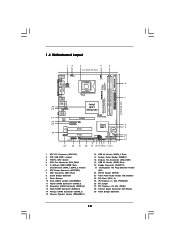
... Top: Line In Center: Line Out Bottom: Mic In AT X 1 2 V 1 DDRII_2 (64 bit, 240-pin module) DDRII_1 (64 bit, 240-pin module) VGA1 IDE1 4Core1600-D800 Quad Core CPU FSB1600 USB 2.0 T: USB2 B: USB3 USB 2.0 T: USB0 B: USB1 Top: RJ-45 AUDIO CODEC CD1 Intel G31 Chipset PCIE1 LAN PHY FD 1 PCIE2/DE PCI1 Super... SATAII_2 23 22 21 20 19 18 171615 14 13 SATAII 24.4cm (9.6 in) 6 7 8 9 10 11 12 1 ATX 12V Connector (ATX12V1) 2 PS2_USB_PWR1 Jumper 3 775-Pin CPU Socket 4 CPU Fan Connector (CPU_FAN1) 5 2 x 240-pin DDR2 DIMM Slots (Dual Channel: DDRII_1, DDRII_2;
... Top: Line In Center: Line Out Bottom: Mic In AT X 1 2 V 1 DDRII_2 (64 bit, 240-pin module) DDRII_1 (64 bit, 240-pin module) VGA1 IDE1 4Core1600-D800 Quad Core CPU FSB1600 USB 2.0 T: USB2 B: USB3 USB 2.0 T: USB0 B: USB1 Top: RJ-45 AUDIO CODEC CD1 Intel G31 Chipset PCIE1 LAN PHY FD 1 PCIE2/DE PCI1 Super... SATAII_2 23 22 21 20 19 18 171615 14 13 SATAII 24.4cm (9.6 in) 6 7 8 9 10 11 12 1 ATX 12V Connector (ATX12V1) 2 PS2_USB_PWR1 Jumper 3 775-Pin CPU Socket 4 CPU Fan Connector (CPU_FAN1) 5 2 x 240-pin DDR2 DIMM Slots (Dual Channel: DDRII_1, DDRII_2;

User Manual
Page 13
...open position at approximately 135 degrees. 2.3 CPU Installation For the installation of Intel 775-LAND CPU, please follow the steps below. 775-Pin Socket Overview Before you insert the 775-LAND CPU into the socket if above situation is any bent pin on the socket. Do not force to clear retention tab... edges where are marked with IHS (Integrated Heat Sink) up. Step 1-3. Hold the CPU by depressing down and out on the hook to insert the CPU into the socket, please check if the CPU surface is unclean or if there is found. Pin1 orientation key notch orientation key notch...
...open position at approximately 135 degrees. 2.3 CPU Installation For the installation of Intel 775-LAND CPU, please follow the steps below. 775-Pin Socket Overview Before you insert the 775-LAND CPU into the socket if above situation is any bent pin on the socket. Do not force to clear retention tab... edges where are marked with IHS (Integrated Heat Sink) up. Step 1-3. Hold the CPU by depressing down and out on the hook to insert the CPU into the socket, please check if the CPU surface is unclean or if there is found. Pin1 orientation key notch orientation key notch...
User Manual
Page 14
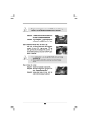
...the IHS. Secure load lever with load plate tab under retention tab of the socket. While pressing down lightly on center of PnP cap to assist in removal. 1. Step 4-3. Step 2-3. Close the socket: Step 4-1. Verify that the CPU is recommended to use the cap tab to handle and avoid kicking off the ...support the load plate edge, engage PnP cap with right hand thumb and peel the cap from the socket while pressing on load plate, engage the load lever. It is within the socket and properly mated to the orient keys. For proper inserting, please ensure to match the two orientation key...
...the IHS. Secure load lever with load plate tab under retention tab of the socket. While pressing down lightly on center of PnP cap to assist in removal. 1. Step 4-3. Step 2-3. Close the socket: Step 4-1. Verify that the CPU is recommended to use the cap tab to handle and avoid kicking off the ...support the load plate edge, engage PnP cap with right hand thumb and peel the cap from the socket while pressing on load plate, engage the load lever. It is within the socket and properly mated to the orient keys. For proper inserting, please ensure to match the two orientation key...

User Manual
Page 15
... and Heatsink This motherboard is an example to the instruction manuals of the heatsink for 775-LAND CPU. Then connect the CPU fan to the CPU fan connector on the socket surface. Step 3. Ensure fan cables are securely fastened and in good contact with remaining fasteners. Secure excess cable... connector on the motherboard. Repeat with each other components. 15 Connect fan header with Intel 775-LAND CPU to ensure cable does not interfere with 775-Pin socket that the CPU and the heatsink are oriented on side closest to the CPU_FAN connector (CPU_FAN1, see page 10, No. ...
... and Heatsink This motherboard is an example to the instruction manuals of the heatsink for 775-LAND CPU. Then connect the CPU fan to the CPU fan connector on the socket surface. Step 3. Ensure fan cables are securely fastened and in good contact with remaining fasteners. Secure excess cable... connector on the motherboard. Repeat with each other components. 15 Connect fan header with Intel 775-LAND CPU to ensure cable does not interfere with 775-Pin socket that the CPU and the heatsink are oriented on side closest to the CPU_FAN connector (CPU_FAN1, see page 10, No. ...
Quick Installation Guide
Page 2
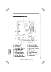
... PCI Express x1 Slot (PCIE2/DE) 26 FD Jumper 27 PCI Express x16 Slot (PCIE1) 28 Internal Audio Connector: CD1 (Black) 29 North Bridge Controller 2 ASRock 4Core1600-D800 Motherboard Motherboard Layout English 1 ATX 12V Connector (ATX12V1) 2 PS2_USB_PWR1 Jumper 3 775-Pin CPU Socket 4 CPU Fan Connector (CPU_FAN1) 5 2 x 240-pin DDR2 DIMM Slots (Dual Channel: DDRII_1, DDRII_2;
... PCI Express x1 Slot (PCIE2/DE) 26 FD Jumper 27 PCI Express x16 Slot (PCIE1) 28 Internal Audio Connector: CD1 (Black) 29 North Bridge Controller 2 ASRock 4Core1600-D800 Motherboard Motherboard Layout English 1 ATX 12V Connector (ATX12V1) 2 PS2_USB_PWR1 Jumper 3 775-Pin CPU Socket 4 CPU Fan Connector (CPU_FAN1) 5 2 x 240-pin DDR2 DIMM Slots (Dual Channel: DDRII_1, DDRII_2;
Quick Installation Guide
Page 9
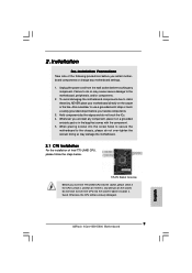
Whenever you handle components. 3. Otherwise, the CPU will be seriously damaged. 9 ASRock 4Core1600-D800 Motherboard English Unplug the power cord from the wall socket before you insert the 775-LAND CPU into the socket, please check if the CPU surface is unclean or if there is found. 2. Also remember to use a grounded wrist strap or touch a safety grounded object...
Whenever you handle components. 3. Otherwise, the CPU will be seriously damaged. 9 ASRock 4Core1600-D800 Motherboard English Unplug the power cord from the wall socket before you insert the 775-LAND CPU into the socket, please check if the CPU surface is unclean or if there is found. 2. Also remember to use a grounded wrist strap or touch a safety grounded object...
Quick Installation Guide
Page 10
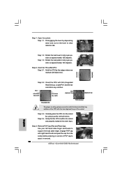
...index finger and thumb to assist in removal. 10 ASRock 4Core1600-D800 Motherboard Step 1-3. Carefully place the CPU into the socket by the edges where are marked with IHS (Integrated Heat Sink) up. Step 2-4. Step 3. Open the socket: Step 1-1. Pin1 orientation key notch orientation key notch ...Pin1 alignment key alignment key 775-LAND CPU 775-Pin Socket For proper inserting, please ensure to match the two orientation key notches ...
...index finger and thumb to assist in removal. 10 ASRock 4Core1600-D800 Motherboard Step 1-3. Carefully place the CPU into the socket by the edges where are marked with IHS (Integrated Heat Sink) up. Step 2-4. Step 3. Open the socket: Step 1-1. Pin1 orientation key notch orientation key notch ...Pin1 alignment key alignment key 775-LAND CPU 775-Pin Socket For proper inserting, please ensure to match the two orientation key notches ...
Quick Installation Guide
Page 11
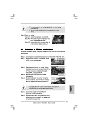
... interfere with the CPU fan connector on fastener caps with remaining fasteners. Step 1. Step 4. Place the heatsink onto the socket. Rotate the fastener clockwise, then press down on the motherboard. Connect fan header with fan operation or contact other components. 11 ASRock 4Core1600-D800 Motherboard English Secure ... load plate onto the IHS. Step 6. Align fasteners with load plate tab under retention tab of load lever. 2.2 Installation of CPU Fan and Heatsink For proper installation, please kindly refer to the CPU fan connector on the socket surface. Step 4.
... interfere with the CPU fan connector on fastener caps with remaining fasteners. Step 1. Step 4. Place the heatsink onto the socket. Rotate the fastener clockwise, then press down on the motherboard. Connect fan header with fan operation or contact other components. 11 ASRock 4Core1600-D800 Motherboard English Secure ... load plate onto the IHS. Step 6. Align fasteners with load plate tab under retention tab of load lever. 2.2 Installation of CPU Fan and Heatsink For proper installation, please kindly refer to the CPU fan connector on the socket surface. Step 4.


