User Manual
Page 12
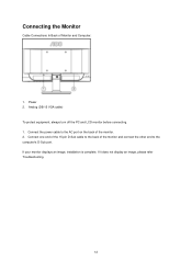
Analog (DB-15 VGA cable) To protect equipment, always turn off the PC and LCD monitor before connecting. 1. If your monitor displays an image, installation is complete. Connecting the Monitor Cable Connections In Back of the monitor. 2. Connect the power cable to the computer's D-Sub port. If it does not display an image, please refer Troubleshooting. 12 Connect one end of the 15-pin D-Sub cable to the back of the monitor and connect the other end to the AC port on the back of Monitor and Computer: 1. Power 2.
Analog (DB-15 VGA cable) To protect equipment, always turn off the PC and LCD monitor before connecting. 1. If your monitor displays an image, installation is complete. Connecting the Monitor Cable Connections In Back of the monitor. 2. Connect the power cable to the computer's D-Sub port. If it does not display an image, please refer Troubleshooting. 12 Connect one end of the 15-pin D-Sub cable to the back of the monitor and connect the other end to the AC port on the back of Monitor and Computer: 1. Power 2.

User Manual
Page 15
5 Click Display Settings. 6 Set the resolution SLIDE-BAR to 1366 by 768. 15
5 Click Display Settings. 6 Set the resolution SLIDE-BAR to 1366 by 768. 15
User Manual
Page 47
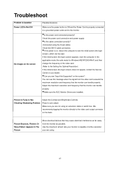
...Resolution) If the initial screen (the login screen) does not appear, contact the Service Center or your are using the D-sub cable) Check the DB-15 cable connection. Make sure you see "Input Not Supported" on the back . Is the cable connected correctly? (Connected using . 47 You can see.... If the power is properly connected to a grounded power outlet and to the video card output connector on the screen? Make sure the AOC Monitor Drivers are not using an extension cable or switch box. Picture Bounces, Flickers Or Wave Pattern Appears In The Picture Move electrical devices ...
...Resolution) If the initial screen (the login screen) does not appear, contact the Service Center or your are using the D-sub cable) Check the DB-15 cable connection. Make sure you see "Input Not Supported" on the back . Is the cable connected correctly? (Connected using . 47 You can see.... If the power is properly connected to a grounded power outlet and to the video card output connector on the screen? Make sure the AOC Monitor Drivers are not using an extension cable or switch box. Picture Bounces, Flickers Or Wave Pattern Appears In The Picture Move electrical devices ...
User Manual
Page 49
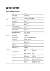
.... Display Color Dot Clock Horizontal scan range Horizontal scan Size(Maximum) Vertical scan range Vertical scan Size(Maximum) Optimal preset resolution Plug & Play Input Connector E1660Sw TFT Color LCD 39.5 cm diagonal 0.252 mm (H) x 0. 252 mm (V) R, G, B Analog lnterface H/V TTL 262,144 Colors 85.5 MHz 30 kHz - ...60 kHz 344.2 mm 60 Hz - 70 Hz 193.5 mm 1366 x 768 (60 Hz) VESA DDC2B D-Sub 15 pin, Input Video Signal Analog: 0.7Vp-p(standard), 75 OHM, Power Source Power Consumption Off timer Connector Type Signal Cable Type Physical Characteristics Dimensions & Weight ...
.... Display Color Dot Clock Horizontal scan range Horizontal scan Size(Maximum) Vertical scan range Vertical scan Size(Maximum) Optimal preset resolution Plug & Play Input Connector E1660Sw TFT Color LCD 39.5 cm diagonal 0.252 mm (H) x 0. 252 mm (V) R, G, B Analog lnterface H/V TTL 262,144 Colors 85.5 MHz 30 kHz - ...60 kHz 344.2 mm 60 Hz - 70 Hz 193.5 mm 1366 x 768 (60 Hz) VESA DDC2B D-Sub 15 pin, Input Video Signal Analog: 0.7Vp-p(standard), 75 OHM, Power Source Power Consumption Off timer Connector Type Signal Cable Type Physical Characteristics Dimensions & Weight ...
User Manual
Page 51
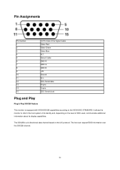
... GND-R GND-G GND-B +5V Ground N.C. The host can request EDID information over the DDC2B channel. 51 Pin Assignments Pin Number 1 2 3 4 5 6 7 8 9 10 11 12 13 14 15 15-Pin Side of its display capabilities.
... GND-R GND-G GND-B +5V Ground N.C. The host can request EDID information over the DDC2B channel. 51 Pin Assignments Pin Number 1 2 3 4 5 6 7 8 9 10 11 12 13 14 15 15-Pin Side of its display capabilities.
User Manual
Page 52
... FCC Rules. This equipment generates, uses and can be used in a particular installation. However, there is not responsible for a Class B digital device, pursuant to Part 15 of the following measures: Reorient or relocate the receiving antenna. Consult the dealer or an experienced radio/TV technician for compliance could void the user...
... FCC Rules. This equipment generates, uses and can be used in a particular installation. However, there is not responsible for a Class B digital device, pursuant to Part 15 of the following measures: Reorient or relocate the receiving antenna. Consult the dealer or an experienced radio/TV technician for compliance could void the user...