User's Manual 2036Sa
Page 14
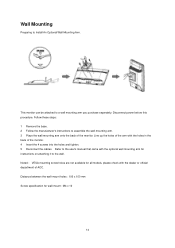
... monitor can be attached to Install An Optional Wall Mounting Arm. Refer to the user's manual that came with the dealer or official department of AOC. Distance between the wall-mount holes : 100 x 100 mm Screw specification for instructions on attaching it to assemble the wall mounting arm. 3 Place the wall...: 1 Remove the base. 2 Follow the manufacturer's instructions to the wall. Disconnect power before this procedure. Noted : VESA mounting screw holes are not available for all models, please check with the optional wall mounting arm for wall-mount : M4 x 10 14
... monitor can be attached to Install An Optional Wall Mounting Arm. Refer to the user's manual that came with the dealer or official department of AOC. Distance between the wall-mount holes : 100 x 100 mm Screw specification for instructions on attaching it to assemble the wall mounting arm. 3 Place the wall...: 1 Remove the base. 2 Follow the manufacturer's instructions to the wall. Disconnect power before this procedure. Noted : VESA mounting screw holes are not available for all models, please check with the optional wall mounting arm for wall-mount : M4 x 10 14
User's Manual 2036Sa
Page 19
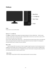
Once the desired function is closed , press button will be Source hot key function (Only for the models with dual or more inputs) .Press Source button continuously to select the input source showed in the message bar , press Menu/Enter button to change ...
Once the desired function is closed , press button will be Source hot key function (Only for the models with dual or more inputs) .Press Source button continuously to select the input source showed in the message bar , press Menu/Enter button to change ...
User's Manual 2036Sa
Page 37
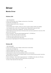
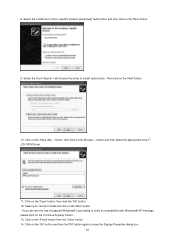
... 'Next' button. 7. Start Windows® 2000 2. Please follow the steps given below. 6. Click on the 'Next' button. 11. Select your monitor model and click on the 'Browse...' Select 'Specify the location of the known drivers for this device so that I can see the 'Digital Signature Not Found... on the 'Start' button, point to 'Settings', and then click on 'Have Disk...'. 8. If the 'Properties' button is inactive, it means your monitor model and click on 'Finish' button then the 'Close' button. 37 Click on 'Change...' If you want', then click on 'Next' and then click on...
... 'Next' button. 7. Start Windows® 2000 2. Please follow the steps given below. 6. Click on the 'Next' button. 11. Select your monitor model and click on the 'Browse...' Select 'Specify the location of the known drivers for this device so that I can see the 'Digital Signature Not Found... on the 'Start' button, point to 'Settings', and then click on 'Have Disk...'. 8. If the 'Properties' button is inactive, it means your monitor model and click on 'Finish' button then the 'Close' button. 37 Click on 'Change...' If you want', then click on 'Next' and then click on...
User's Manual 2036Sa
Page 40
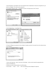
... the 'OK' button again to close the Display Properties dialog box. 40 Click on the 'Have disk...' Click on the 'Next' button. - Select your monitor model and click on the 'Finish' button then the 'Close' button. 14. 8.
... the 'OK' button again to close the Display Properties dialog box. 40 Click on the 'Have disk...' Click on the 'Next' button. - Select your monitor model and click on the 'Finish' button then the 'Close' button. 14. 8.
User's Manual 2036Sa
Page 42
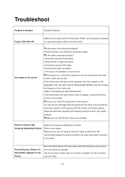
... appropriate drive F:\Driver (CD-ROM Drive). 8. Click on the 'Browse...' button, then click on the 'Have disk...' 4. Check the "Browse my computer for your monitor model and click on my computer". 7. Click "Close" → "Close" → "OK" → "OK" on the following screens displayed in the "Driver" tab. 6. Click "Update Driver...
... appropriate drive F:\Driver (CD-ROM Drive). 8. Click on the 'Browse...' button, then click on the 'Have disk...' 4. Check the "Browse my computer for your monitor model and click on my computer". 7. Click "Close" → "Close" → "OK" → "OK" on the following screens displayed in the "Driver" tab. 6. Click "Update Driver...
User's Manual 2036Sa
Page 44
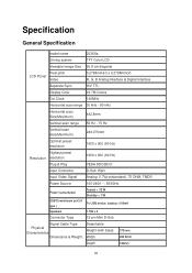
... cable connection. * DVI input is not available on the screen? Adjust the maximum resolution and frequency that the monitor can handle properly. Make sure the AOC Monitor Drivers are using. 44 No images on the back . Is the cable connected correctly? (Connected using the D-sub cable) Check the DB-15 cable... the initial screen (the login screen) does not appear, contact the Service Center or your are installed. Press to see "Input Not Supported" on every model. Check the power cord connection and power supply.
... cable connection. * DVI input is not available on the screen? Adjust the maximum resolution and frequency that the monitor can handle properly. Make sure the AOC Monitor Drivers are using. 44 No images on the back . Is the cable connected correctly? (Connected using the D-sub cable) Check the DB-15 cable... the initial screen (the login screen) does not appear, contact the Service Center or your are installed. Press to see "Input Not Supported" on every model. Check the power cord connection and power supply.
User's Manual 2036Sa
Page 46
..., TMDS Power Source 100-240V~, 50/60Hz Power Consumption USB Downstream port (A type ) Speakers Typical < 32 W Standby < 1 W To USB device, loading Specification General Specification model name 2036Sa Driving system TFT Color LCD Viewable Image Size 50.8 cm diagonal Pixel pitch LCD Panel Video 0.2768mm(H) x 0.2768mm(V) R, G, B Analog lnterface & Digital Interface Separate Sync.
..., TMDS Power Source 100-240V~, 50/60Hz Power Consumption USB Downstream port (A type ) Speakers Typical < 32 W Standby < 1 W To USB device, loading Specification General Specification model name 2036Sa Driving system TFT Color LCD Viewable Image Size 50.8 cm diagonal Pixel pitch LCD Panel Video 0.2768mm(H) x 0.2768mm(V) R, G, B Analog lnterface & Digital Interface Separate Sync.
User's Manual 2036Sa
Page 50
... used in a residential installation. Increase the separation between the equipment and receiver. Regulation FCC Notice FCC Class B Radio Frequency Interference Statement WARNING: (FOR FCC CERTIFIED MODELS) NOTE: This equipment has been tested and found to comply with the emission limits. These limits are designed to provide reasonable protection against harmful interference...
... used in a residential installation. Increase the separation between the equipment and receiver. Regulation FCC Notice FCC Class B Radio Frequency Interference Statement WARNING: (FOR FCC CERTIFIED MODELS) NOTE: This equipment has been tested and found to comply with the emission limits. These limits are designed to provide reasonable protection against harmful interference...
