
Service Manual
Page 1
CDC-Z107 YU SERVICE MANUAL STEREO CAR CD RECEIVER BASIC CD MECHANISM : TN-CCD1001-113J • This Service Manual is the "Revision Publishing" and replaces "Simple Manual" of CDC-Z107, (S/M Code No. 09-99B-422-4T1). S/M Code No. 09-002-422-4R1 REVISIODNATA
CDC-Z107 YU SERVICE MANUAL STEREO CAR CD RECEIVER BASIC CD MECHANISM : TN-CCD1001-113J • This Service Manual is the "Revision Publishing" and replaces "Simple Manual" of CDC-Z107, (S/M Code No. 09-99B-422-4T1). S/M Code No. 09-002-422-4R1 REVISIODNATA

Service Manual
Page 2
... dB) Set the frequency increment for your area using the switch on the bottom of the unit. (The switch is set at 10 kHz Preamp Output Voltage (load impedance) 2.2 V (10 kΩ) Installation Size 182 (W) x 53 (H) x 155 (D) mm (71/4 (W) x 21/8 (H) x 61/8 (D) inches) • Design and specifications are subject to the 10k position [for the U.S.A.]) CD SECTION Frequency Response Dynamic Range Channel Separation S/N Ratio...
... dB) Set the frequency increment for your area using the switch on the bottom of the unit. (The switch is set at 10 kHz Preamp Output Voltage (load impedance) 2.2 V (10 kΩ) Installation Size 182 (W) x 53 (H) x 155 (D) mm (71/4 (W) x 21/8 (H) x 61/8 (D) inches) • Design and specifications are subject to the 10k position [for the U.S.A.]) CD SECTION Frequency Response Dynamic Range Channel Separation S/N Ratio...
Service Manual
Page 3
... SERVICING This set employs laser. WHEN SERVICING, DO NOT APPROACH THE LASER EXIT WITH THE EYE TOO CLOSELY. ADVARSEL Usynlig laserståling ved åbning, når sikkerhedsafbrydereer ude af funktion. This Compact Disc player is located on the rear exterior. Be sure ground body and workbench, and use care the clothes do not touch the diode. 1) After the connection, remove...
... SERVICING This set employs laser. WHEN SERVICING, DO NOT APPROACH THE LASER EXIT WITH THE EYE TOO CLOSELY. ADVARSEL Usynlig laserståling ved åbning, når sikkerhedsafbrydereer ude af funktion. This Compact Disc player is located on the rear exterior. Be sure ground body and workbench, and use care the clothes do not touch the diode. 1) After the connection, remove...

Service Manual
Page 5
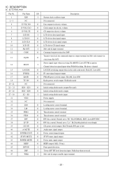
...-F12X-K1 CONN,14P TKC-F14X-K1 CONN,16P CAM-B51 FUSE,15A 32V J101 J451 L101 L102 L671 8Z-KT1-614-010...8Z-KT1-619-010 87-003-149-080 ANT,AW-002 JACK,PIN 2P XR-401 COIL 4.7 UH COIL,68MH K7-D COIL,47UH...-KC8-621-010 81-592-641-010 87-A70-175-010 TU UNIT, FAE347-A12 VIB,CER 16.93MHZ VIB,XTAL 4.5MHZ AT-49 FRONT...17 LED,SEL6227S RED LED,SEL6227S RED LED,SEL6227S RED C-LED,SEC1E01C BLUE C-LED,SEC1E01C BLUE C-LED,SEC1E01C BLUE LAMP,T-3 LAMP,T-3 SW,T CT 6X3.5 160 SW,T CT 6X3.5 ...CT 6X3.5 160 SW,RTRY SIM-026MT SW,T CT 6X3.5 160 AUX C.B CON831 87-A60-912-010 J831 85-HRL-623-010 CONN,3P V 1MSA-9202B-1...
...-F12X-K1 CONN,14P TKC-F14X-K1 CONN,16P CAM-B51 FUSE,15A 32V J101 J451 L101 L102 L671 8Z-KT1-614-010...8Z-KT1-619-010 87-003-149-080 ANT,AW-002 JACK,PIN 2P XR-401 COIL 4.7 UH COIL,68MH K7-D COIL,47UH...-KC8-621-010 81-592-641-010 87-A70-175-010 TU UNIT, FAE347-A12 VIB,CER 16.93MHZ VIB,XTAL 4.5MHZ AT-49 FRONT...17 LED,SEL6227S RED LED,SEL6227S RED LED,SEL6227S RED C-LED,SEC1E01C BLUE C-LED,SEC1E01C BLUE C-LED,SEC1E01C BLUE LAMP,T-3 LAMP,T-3 SW,T CT 6X3.5 160 SW,T CT 6X3.5 ...CT 6X3.5 160 SW,RTRY SIM-026MT SW,T CT 6X3.5 160 AUX C.B CON831 87-A60-912-010 J831 85-HRL-623-010 CONN,3P V 1MSA-9202B-1...
Service Manual
Page 11
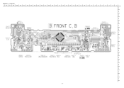
WIRING - 2 (FRONT) 32 31 30 29 28 27 26 25 24 23 22 21 20 19 18 17 16 15 14 13 12 11 10 9 8 7 6 5 4 3 2 1 A B C D E F G H I J K L M N O P Q R S T U - 11 -
WIRING - 2 (FRONT) 32 31 30 29 28 27 26 25 24 23 22 21 20 19 18 17 16 15 14 13 12 11 10 9 8 7 6 5 4 3 2 1 A B C D E F G H I J K L M N O P Q R S T U - 11 -
Service Manual
Page 23
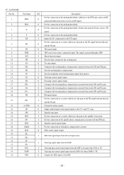
... IC, LC72358N-9910 Pin No. Stereo signal input when receiving. Hi=detect channel 15 LOC/DX O LOC/DX switching output when in 13 CQCK O clock from SQ OUT. Hi=AM, Low=FM 18 TU ON O Radio power switch output. Not connected. 22 ~ 23 KS4 ~ KS3 O Initial setting diode matrix output(Not used . 47 WRQ I "Detect RF" RF level detection input. Not connected. 33 LM+ O Loading motor control terminal. 34 LM...
... IC, LC72358N-9910 Pin No. Stereo signal input when receiving. Hi=detect channel 15 LOC/DX O LOC/DX switching output when in 13 CQCK O clock from SQ OUT. Hi=AM, Low=FM 18 TU ON O Radio power switch output. Not connected. 22 ~ 23 KS4 ~ KS3 O Initial setting diode matrix output(Not used . 47 WRQ I "Detect RF" RF level detection input. Not connected. 33 LM+ O Loading motor control terminal. 34 LM...

Service Manual
Page 24
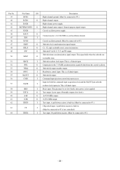
... mode. Not used . O Error out from charge pump (for level indecator. I ACC (accessory power) ON/ OFF input. I Voltage input for FM / AM). - I Pick up when not used . - Pulled up inner track position detection. Not connected. Power supply. O DSP reset output terminal. I Remote controller input. I Disc detection / chuck or release disc detection. I FM channel transmission input. - O Security LED flashing output. I IF count signal input (FM / AM). - Low=-20dB mute. Not connected. I CD test mode. I Rotary encoder input...
... mode. Not used . O Error out from charge pump (for level indecator. I ACC (accessory power) ON/ OFF input. I Voltage input for FM / AM). - I Pick up when not used . - Pulled up inner track position detection. Not connected. Power supply. O DSP reset output terminal. I Remote controller input. I Disc detection / chuck or release disc detection. I FM channel transmission input. - O Security LED flashing output. I IF count signal input (FM / AM). - Low=-20dB mute. Not connected. I CD test mode. I Rotary encoder input...
Service Manual
Page 25
... O signal and subtraction from the DSP. O For the connection of the pickup photodiode. I Sets the tracking phase compensation. O Tracking control signal output. O Focusing control signal output. O Spindle control signal output. Subtraction from the DSP. O TE signal output. I Shock detection input. I TES (track error sense) comparator input. O FE signal output. pins. Off when TOFF is "H". I Spindle amp input. I Sets the amplitude of the FE signal between the FD...
... O signal and subtraction from the DSP. O For the connection of the pickup photodiode. I Sets the tracking phase compensation. O Tracking control signal output. O Focusing control signal output. O Spindle control signal output. Subtraction from the DSP. O TE signal output. I Shock detection input. I TES (track error sense) comparator input. O FE signal output. pins. Off when TOFF is "H". I Spindle amp input. I Sets the amplitude of the FE signal between the FD...

Service Manual
Page 26
... circuits. - I APC circuit input. - I The TBC (tracking balance control) signal sets the EF balance variation range. - VCC of digital signals. O APC circuit output. The FSS (focus search select) signal switches the focus search modes (+/-search / I +search with the O RFSM pin. I Microprocessor command data input. I /O Description The HFL (high frequency level) signal is used to the reference voltage). (Not connected) - Sets the time constant for disc defect detection. - SLC...
... circuits. - I APC circuit input. - I The TBC (tracking balance control) signal sets the EF balance variation range. - VCC of digital signals. O APC circuit output. The FSS (focus search select) signal switches the focus search modes (+/-search / I +search with the O RFSM pin. I Microprocessor command data input. I /O Description The HFL (high frequency level) signal is used to the reference voltage). (Not connected) - Sets the time constant for disc defect detection. - SLC...

Service Manual
Page 27
... connected to 0V.) PDO output current adjustment resistor connection. Internal VCO power supply. VCO frequency range adjustment. Digital system ground. (Must be connected to 0V.) Slice level control EFM signal output. Slice level control EFM signal input. Test input. Can be connected to three-value output by microprocessor command. Rough servo/phase control automatic switching monitor output. Track detection signal input. Tracking off output. Increase the gain when low. Track jump output. Output a high level...
... connected to 0V.) PDO output current adjustment resistor connection. Internal VCO power supply. VCO frequency range adjustment. Digital system ground. (Must be connected to 0V.) Slice level control EFM signal output. Slice level control EFM signal input. Test input. Can be connected to three-value output by microprocessor command. Rough servo/phase control automatic switching monitor output. Track detection signal input. Tracking off output. Increase the gain when low. Track jump output. Output a high level...
Service Manual
Page 28
... I Description Right channel ground. (Must be connected to 0V if not controlled.) Test input. Right channel mute output./ General purpose input/ output. This signal falls when the subcode are in . (Must be set low briefly after power is a Schmitt input. Subcode readout clock input. Input for a 16.9344 MHz crystal oscillator element. Test output. Subcode frame synchronization signal output. This is first applied. Test input. Pin No. 39 40...
... I Description Right channel ground. (Must be connected to 0V if not controlled.) Test input. Right channel mute output./ General purpose input/ output. This signal falls when the subcode are in . (Must be set low briefly after power is a Schmitt input. Subcode readout clock input. Input for a 16.9344 MHz crystal oscillator element. Test output. Subcode frame synchronization signal output. This is first applied. Test input. Pin No. 39 40...

Service Manual
Page 29
... as a troubleshooting against power ripples. I 4dB volume control input. O Tone control output. 29 ~ 31 LT3 ~ LT1 For the connection of RCH super bass compensation capacitors. A high-frequency compensation capacitors must be connected between T1 and T2. For the connection of capacitors that compensate for control. Must be driven at a low impedance. 34 LSELO O Input selector output pin. 35 AUX(L) 36 CD(L) I Serial data and clock inputs for bass and treble in...
... as a troubleshooting against power ripples. I 4dB volume control input. O Tone control output. 29 ~ 31 LT3 ~ LT1 For the connection of RCH super bass compensation capacitors. A high-frequency compensation capacitors must be connected between T1 and T2. For the connection of capacitors that compensate for control. Must be driven at a low impedance. 34 LSELO O Input selector output pin. 35 AUX(L) 36 CD(L) I Serial data and clock inputs for bass and treble in...

Service Manual
Page 30
... command driver outputs. 44 ~ 49 KS1 ~ KS6 O Key scan outputs. 50 ~ 54 KI1 ~ KI5 I Signal input pins. O Input selector output pin. synchronization. 64 DI O Serial data interface pin; Test pin. (Connected to GND.) 60 OSC I VDD1 when a 1/2 bias drive scheme is used.) Used for applying the LCD drive 1/3 bias voltage externally. (Must be connected to 57 VDD1 I VDD2 when a 1/2 bias drive scheme is used. 59 VSS - Power supply. Power supply. (Connected...
... command driver outputs. 44 ~ 49 KS1 ~ KS6 O Key scan outputs. 50 ~ 54 KI1 ~ KI5 I Signal input pins. O Input selector output pin. synchronization. 64 DI O Serial data interface pin; Test pin. (Connected to GND.) 60 OSC I VDD1 when a 1/2 bias drive scheme is used.) Used for applying the LCD drive 1/3 bias voltage externally. (Must be connected to 57 VDD1 I VDD2 when a 1/2 bias drive scheme is used. 59 VSS - Power supply. Power supply. (Connected...
Service Manual
Page 31
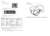
... pin (VDD) of power supply/speaker connector to DC+12V, then connect Ground (black) to use extension jig. and CD mechanisms by cable. 2) Connect wire of ACC (red) and BACKUP (yellow) of the MAIN C.B IC701 (LC72358N-9910) and switch on MAIN C.B to the 31 pin (VDD) by extension jigs when checking CD mechanism (TN-CCD1001-113J) operation. (Refer to the following figure. Playing Time...
... pin (VDD) of power supply/speaker connector to DC+12V, then connect Ground (black) to use extension jig. and CD mechanisms by cable. 2) Connect wire of ACC (red) and BACKUP (yellow) of the MAIN C.B IC701 (LC72358N-9910) and switch on MAIN C.B to the 31 pin (VDD) by extension jigs when checking CD mechanism (TN-CCD1001-113J) operation. (Refer to the following figure. Playing Time...


