
Operating Instructions
Page 4
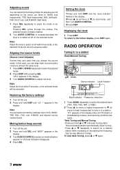
...on /off within 5 seconds, or the selected mode will return to set minute), and then turn AUDIO CONTROL. 3 Press DISP. Restoring the factory settings 1 Turn off the unit. 2 Press and hold i or k until the clock indicator flashes in the display. Muting button beep sounds 1 Turn off ...appear) or off the unit. 2 Press and hold DISP until seek Tuning starts. Setting the clock 1 Press and hold SEL until "LA --" appears in the display. 2 Press i (to set hour) or k (to previous state. Displaying the clock 1 Press DISP. The unit locates a station automatically (Seek Tuning). • Press ...
...on /off within 5 seconds, or the selected mode will return to set minute), and then turn AUDIO CONTROL. 3 Press DISP. Restoring the factory settings 1 Turn off the unit. 2 Press and hold i or k until the clock indicator flashes in the display. Muting button beep sounds 1 Turn off ...appear) or off the unit. 2 Press and hold DISP until seek Tuning starts. Setting the clock 1 Press and hold SEL until "LA --" appears in the display. 2 Press i (to set hour) or k (to previous state. Displaying the clock 1 Press DISP. The unit locates a station automatically (Seek Tuning). • Press ...
Operating Instructions
Page 6
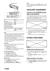
...monitoring the first 10 seconds of all the tracks in Press and hold SEL until "ILL" appears in the display. During AUX mode, the clock display appears. To cancel Random Play, press RNDM again. AUX jack 1 Connect a cassette/MD/MP3 portable player or other equipment You can... choose blue or red as the key illumination color. 1 Press and hold SRC until "D" appears in the display. Setting the dimmer of the display 1 Press and hold r or a track t until "AUX" appears in the display. 2 Turn AUDIO CONTROL to select "D 0 (bright)" or "D ...
...monitoring the first 10 seconds of all the tracks in Press and hold SEL until "ILL" appears in the display. During AUX mode, the clock display appears. To cancel Random Play, press RNDM again. AUX jack 1 Connect a cassette/MD/MP3 portable player or other equipment You can... choose blue or red as the key illumination color. 1 Press and hold SRC until "D" appears in the display. Setting the dimmer of the display 1 Press and hold r or a track t until "AUX" appears in the display. 2 Turn AUDIO CONTROL to select "D 0 (bright)" or "D ...
Service Manual
Page 28
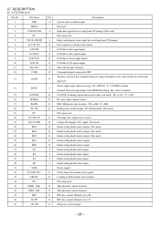
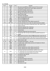
... terminal. 12 COIN O Command output terminal for sub-code transfer-in the radio seek mode. Transfer-out clock for command output or output terminal for DSP. Normal set to "L". 39 CD ON O CD power switch output. - 28 - IC DESCRIPTION IC, LC72358N-9A71 Pin...Not used ) 25 KS1 O Initial setting diode matrix output. 26 KS0 O Initial setting diode matrix output. 27 K3 I Initial setting diode matrix input. 28 K2 I Initial setting diode matrix input. 29 K1 I Initial setting diode matrix input. 30 K0 I Input synchronous clock signal for volume level control. 33...
... terminal. 12 COIN O Command output terminal for sub-code transfer-in the radio seek mode. Transfer-out clock for command output or output terminal for DSP. Normal set to "L". 39 CD ON O CD power switch output. - 28 - IC DESCRIPTION IC, LC72358N-9A71 Pin...Not used ) 25 KS1 O Initial setting diode matrix output. 26 KS0 O Initial setting diode matrix output. 27 K3 I Initial setting diode matrix input. 28 K2 I Initial setting diode matrix input. 29 K1 I Initial setting diode matrix input. 30 K0 I Input synchronous clock signal for volume level control. 33...
Service Manual
Page 31
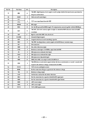
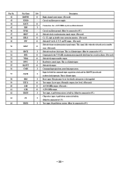
...the DSP's data slice level. - I Microprocessor command data input. I Microprocessor command clock input. The FSS (focus search select) signal switches the focus search modes (+/-search / +search with the RFSM pin. Set the time constant for the focus search smoothing capacitor. VCC of servo and digital ...I /O Description The HFL (high frequency level) signal is output to detect the RF level. O Set the RF gain and the EFM singal's 3T compensation constant together with I Reference clock input. 4.23 MHz is an output to control the DSP's data slice level of a capacitor to ...
...the DSP's data slice level. - I Microprocessor command data input. I Microprocessor command clock input. The FSS (focus search select) signal switches the focus search modes (+/-search / +search with the RFSM pin. Set the time constant for the focus search smoothing capacitor. VCC of servo and digital ...I /O Description The HFL (high frequency level) signal is output to detect the RF level. O Set the RF gain and the EFM singal's 3T compensation constant together with I Reference clock input. 4.23 MHz is an output to control the DSP's data slice level of a capacitor to ...
Service Manual
Page 32
....) I "H": Control possible only for all commands. (Must be connected to 0V when not in . This is a Schmitt input. O EFM data playback clock monitor. Digital system power supply. A pull-down resistor is locked. (Not used ) - Internal VCO power supply. O Tracking off output. I Tracking... when the phase is built-in. (Must be connected to 0V.) - Left channel power supply. Internal VCO ground. (Must be set to 0V.) O Slice level control EFM signal output. Rough servo/phase control automatic switching monitor output. O Left channel output. - ...
....) I "H": Control possible only for all commands. (Must be connected to 0V when not in . This is a Schmitt input. O EFM data playback clock monitor. Digital system power supply. A pull-down resistor is locked. (Not used ) - Internal VCO power supply. O Tracking off output. I Tracking... when the phase is built-in. (Must be connected to 0V.) - Left channel power supply. Internal VCO ground. (Must be set to 0V.) O Slice level control EFM signal output. Rough servo/phase control automatic switching monitor output. O Left channel output. - ...
Service Manual
Page 33
This is built-in. (Must be set low briefly after power is a Schmitt input. I Test input. I Reset input. A pull-down resistor is Schmitt input. Crystal oscillator power supply. O Connection for both the command input acquisition clock and the SQOUT pin subcode I Read/write...EFLG PW SFSY SBCK FSX WRQ RWC SQOUT COIN CQCK RES TST11 16M 4.2M TEST5 CS TEST1 I Subcode read out clock input. Crystal oscillator ground. (Must be connected to 0V.) O Subcode clock synchronization signal output. (Not used) O C1, C2, sigle an double error correction monitor. (Not used) O ...
This is built-in. (Must be set low briefly after power is a Schmitt input. I Test input. I Reset input. A pull-down resistor is Schmitt input. Crystal oscillator power supply. O Connection for both the command input acquisition clock and the SQOUT pin subcode I Read/write...EFLG PW SFSY SBCK FSX WRQ RWC SQOUT COIN CQCK RES TST11 16M 4.2M TEST5 CS TEST1 I Subcode read out clock input. Crystal oscillator ground. (Must be connected to 0V.) O Subcode clock synchronization signal output. (Not used) O C1, C2, sigle an double error correction monitor. (Not used) O ...
