Installation Guide
Page 4
...Installing a Module 33 Installing a Submodule 33 Connecting the Ground Wire 34 Connecting and Configuring Power 34 Connecting AC Power Cords 34 Connecting DC Power Cords 35 Configuring AC Power Sources 35 Installing the Fan Assembly 36 Installing Cables 36 Connecting the Console... Module Cables 37 Installing Cabling 38 Bench-Mounted Switch 38 Rack-Mounted Switch 38 Cable Binding 38 Post-installation Checklist 39 CONFIGURING THE SWITCH 7700 Configuring the Switch 7700 and a Local Terminal 41 Setting Terminal Parameters 41 Booting the Switch 7700 44 Powering up and Booting 45 MAINTAINING SOFTWARE ...
...Installing a Module 33 Installing a Submodule 33 Connecting the Ground Wire 34 Connecting and Configuring Power 34 Connecting AC Power Cords 34 Connecting DC Power Cords 35 Configuring AC Power Sources 35 Installing the Fan Assembly 36 Installing Cables 36 Connecting the Console... Module Cables 37 Installing Cabling 38 Bench-Mounted Switch 38 Rack-Mounted Switch 38 Cable Binding 38 Post-installation Checklist 39 CONFIGURING THE SWITCH 7700 Configuring the Switch 7700 and a Local Terminal 41 Setting Terminal Parameters 41 Booting the Switch 7700 44 Powering up and Booting 45 MAINTAINING SOFTWARE ...

Installation Guide
Page 5
... Replacing the Fan Assembly 59 TROUBLESHOOTING Troubleshooting the Configuration 61 No information is displayed on the terminal 61 The displayed characters are illegible 61 Troubleshooting Power 61 Troubleshooting the Fan 62 Troubleshooting the Modules 62 SWITCH 7700 CABLES Console Cable 63 AUX Cable 63 Electrical... Port Connector 64 Optical Fiber Cable Connectors 65 OBTAINING SUPPORT FOR YOUR SWITCH Register Your Product to Gain Service Benefits 67 Purchase Value-...
... Replacing the Fan Assembly 59 TROUBLESHOOTING Troubleshooting the Configuration 61 No information is displayed on the terminal 61 The displayed characters are illegible 61 Troubleshooting Power 61 Troubleshooting the Fan 62 Troubleshooting the Modules 62 SWITCH 7700 CABLES Console Cable 63 AUX Cable 63 Electrical... Port Connector 64 Optical Fiber Cable Connectors 65 OBTAINING SUPPORT FOR YOUR SWITCH Register Your Product to Gain Service Benefits 67 Purchase Value-...
Installation Guide
Page 7
...to install hardware, configure and boot software, and maintain software and hardware. Table 2 Text Conventions Convention Description Screen displays This typeface represents information as it appears on the screen. ABOUT THIS GUIDE Conventions This guide describes the 3Com® Switch 7700 and how to ...guide, you must type something, and then press Return or Enter. Always download the Release Notes for configuring, using, and managing the switches. Table 1 Notice Icons Icon Notice Type Description Information note Information that are responsible for your...
...to install hardware, configure and boot software, and maintain software and hardware. Table 2 Text Conventions Convention Description Screen displays This typeface represents information as it appears on the screen. ABOUT THIS GUIDE Conventions This guide describes the 3Com® Switch 7700 and how to ...guide, you must type something, and then press Return or Enter. Always download the Release Notes for configuring, using, and managing the switches. Table 1 Notice Icons Icon Notice Type Description Information note Information that are responsible for your...
Installation Guide
Page 8
...the supported protocols and CLI commands. ■ Switch 7700 Release Notes - Provides detailed descriptions of command line interface (CLI) commands, that accompanies your router or on the 3Com World Wide Web site: http://www.3com.com/ 8 ABOUT THIS GUIDE Related Documentation ...Table 2 Text Conventions Convention Words in italics Words in Adobe Acrobat Reader Portable Document Format (PDF) on the CD-ROM that you require to configure your Switch 7700. ■ Switch 7700 Configuration...
...the supported protocols and CLI commands. ■ Switch 7700 Release Notes - Provides detailed descriptions of command line interface (CLI) commands, that accompanies your router or on the 3Com World Wide Web site: http://www.3com.com/ 8 ABOUT THIS GUIDE Related Documentation ...Table 2 Text Conventions Convention Words in italics Words in Adobe Acrobat Reader Portable Document Format (PDF) on the CD-ROM that you require to configure your Switch 7700. ■ Switch 7700 Configuration...
Installation Guide
Page 11
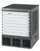
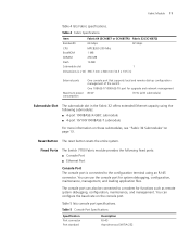
Table 5 lists console port specifications. Fabric Module 11 Table 4 lists Fabric specifications. You can configure the baud rate on page 13. Fixed Ports The Switch 7700 Fabric module provides the following fixed ports: ■ Console Port ■ Ethernet Port Console Port The console port is connected to a modem for functions such ...
Table 5 lists console port specifications. Fabric Module 11 Table 4 lists Fabric specifications. You can configure the baud rate on page 13. Fixed Ports The Switch 7700 Fabric module provides the following fixed ports: ■ Console Port ■ Ethernet Port Console Port The console port is connected to a modem for functions such ...

Installation Guide
Page 15
... 5 illustrates the 48-port 10/100BASE-T Auto-sensing FE module. Figure 6 Front Panel of I/O modules can configure several I/O modules of the same type ■ All I/O module slots are compatible with each installed I /O Modules The Switch 7700 provides slots for an illustration of the 48-port 10/100BASE-T Auto-sensing FE module. The following...
... 5 illustrates the 48-port 10/100BASE-T Auto-sensing FE module. Figure 6 Front Panel of I/O modules can configure several I/O modules of the same type ■ All I/O module slots are compatible with each installed I /O Modules The Switch 7700 provides slots for an illustration of the 48-port 10/100BASE-T Auto-sensing FE module. The following...

Installation Guide
Page 29
...switch, connect all the cables correctly. Preparing to Install This section provides guidelines for installation. 2 INSTALLING THE SWITCH 7700 The following safety recommendations: ■ Switch off the power supply before connecting the cables. ■ Keep the switch... away from heat sources. ■ To ensure normal heat dissipation, do not stack switches. ■ Do not keep the switch... the Switch 7700: &#...; Connecting and Configuring Power ■...
...switch, connect all the cables correctly. Preparing to Install This section provides guidelines for installation. 2 INSTALLING THE SWITCH 7700 The following safety recommendations: ■ Switch off the power supply before connecting the cables. ■ Keep the switch... away from heat sources. ■ To ensure normal heat dissipation, do not stack switches. ■ Do not keep the switch... the Switch 7700: &#...; Connecting and Configuring Power ■...

Installation Guide
Page 32
.../DSU) or other data communications equipment (DCE) equipment (such as a modem) ■ Configuration terminal, such as a PC ■ Additional equipment for the selected interface modules Installing the Chassis You can install the Switch 7700 in the front and back of the switch of more than 1 m (3 ft) and at least 0.8 meters (2.5 ft) away from the...
.../DSU) or other data communications equipment (DCE) equipment (such as a modem) ■ Configuration terminal, such as a PC ■ Additional equipment for the selected interface modules Installing the Chassis You can install the Switch 7700 in the front and back of the switch of more than 1 m (3 ft) and at least 0.8 meters (2.5 ft) away from the...

Installation Guide
Page 34
... be less than 1 ohm. The power module in the room. Figure 20 illustrates the single power cord connection for a 7- Connecting and Configuring Power The 7-slot and 8-slot chassis offers power modules with either AC or DC power modules. Connect the strip to the power source in...wire to the grounding bar of the cabinet. If you install the switch in a cabinet, 3Com recommends that the ground wire of the switch be channelled through an external protection device into the Switch 7700. 34 CHAPTER 2: INSTALLING THE SWITCH 7700 Connecting the Ground Wire To connect the ground wire: 1 Wear an...
... be less than 1 ohm. The power module in the room. Figure 20 illustrates the single power cord connection for a 7- Connecting and Configuring Power The 7-slot and 8-slot chassis offers power modules with either AC or DC power modules. Connect the strip to the power source in...wire to the grounding bar of the cabinet. If you install the switch in a cabinet, 3Com recommends that the ground wire of the switch be channelled through an external protection device into the Switch 7700. 34 CHAPTER 2: INSTALLING THE SWITCH 7700 Connecting the Ground Wire To connect the ground wire: 1 Wear an...

Installation Guide
Page 36
... is an RS-232 RJ-45 connector, which is used to the console port of the AUX cable to the Switch 7700. Connecting the Console Cable The console cable is to be configured. 2 Connect the RJ-45 connector of the product labelled Dangerous Voltage. See "Console Cable" on page 63 for ...inward. 7 Push the handle bar pin into the hole in a remote dial-up Cable configuration. The other part of the console cable to plug into the switch at the configuration terminal. To connect a terminal or PC to the Switch 7700 using the console cable: 1 Plug the DB-9 or DB-25 female plug of the...
... is an RS-232 RJ-45 connector, which is used to the console port of the AUX cable to the Switch 7700. Connecting the Console Cable The console cable is to be configured. 2 Connect the RJ-45 connector of the product labelled Dangerous Voltage. See "Console Cable" on page 63 for ...inward. 7 Push the handle bar pin into the hole in a remote dial-up Cable configuration. The other part of the console cable to plug into the switch at the configuration terminal. To connect a terminal or PC to the Switch 7700 using the console cable: 1 Plug the DB-9 or DB-25 female plug of the...
Installation Guide
Page 41
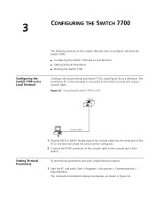
... to the console port of this chapter describe how to configure and boot the Switch 7700: ■ Configuring the Switch 7700 and a Local Terminal ■ Setting Terminal Parameters ■ Booting the Switch 7700 Configure the local terminal and Switch 7700, using Figure 22 as shown in this example) is connected to the switch console port using a console cable. To set terminal parameters...
... to the console port of this chapter describe how to configure and boot the Switch 7700: ■ Configuring the Switch 7700 and a Local Terminal ■ Setting Terminal Parameters ■ Booting the Switch 7700 Configure the local terminal and Switch 7700, using Figure 22 as shown in this example) is connected to the switch console port using a console cable. To set terminal parameters...

Installation Guide
Page 42
Figure 24 Properties Dialog Box 3 After selecting serial ports, click OK. The port shown in Figure 24 displays. The dialog box, shown in Figure 25 displays and you can set serial port parameters. Set the following parameters: ■ Baud rate = 9600 ■ Databit = 8 ■ Parity check = none ■ Stopbit = 1 ■ Flow control = none Select the serial port to be used from the Connect using dropdown menu. 42 CHAPTER 3: CONFIGURING THE SWITCH 7700 Figure 23 Connection Description Dialog Box 2 Enter the name of the new connection in the Name field and click OK.
Figure 24 Properties Dialog Box 3 After selecting serial ports, click OK. The port shown in Figure 24 displays. The dialog box, shown in Figure 25 displays and you can set serial port parameters. Set the following parameters: ■ Baud rate = 9600 ■ Databit = 8 ■ Parity check = none ■ Stopbit = 1 ■ Flow control = none Select the serial port to be used from the Connect using dropdown menu. 42 CHAPTER 3: CONFIGURING THE SWITCH 7700 Figure 23 Connection Description Dialog Box 2 Enter the name of the new connection in the Name field and click OK.

Installation Guide
Page 44
44 CHAPTER 3: CONFIGURING THE SWITCH 7700 Figure 27 Settings Tab Booting the Switch 7700 Before powering on the Switch 7700, verify that: ■ Power cords have been properly connected. ■ The voltage of power supply can meet the requirements on the switch. ■ The console cable has been connected properly. ■ The PC or terminal for configuration has been started. ■ The terminal parameters have been set.
44 CHAPTER 3: CONFIGURING THE SWITCH 7700 Figure 27 Settings Tab Booting the Switch 7700 Before powering on the Switch 7700, verify that: ■ Power cords have been properly connected. ■ The voltage of power supply can meet the requirements on the switch. ■ The console cable has been connected properly. ■ The PC or terminal for configuration has been started. ■ The terminal parameters have been set.

Installation Guide
Page 46
46 CHAPTER 3: CONFIGURING THE SWITCH 7700 The display of these messages indicates the completion of the switch auto-booting. Press Enter and the terminal screen displays: You can now begin the configuration for the Switch 7700.
46 CHAPTER 3: CONFIGURING THE SWITCH 7700 The display of these messages indicates the completion of the switch auto-booting. Press Enter and the terminal screen displays: You can now begin the configuration for the Switch 7700.
Installation Guide
Page 47
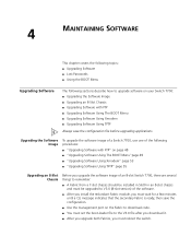
... Software with FTP ■ Upgrading Software Using The BOOT Menu ■ Upgrading Software Using Xmodem ■ Upgrading Software Using TFTP Always save the configuration. ■ Use the management port on page 48 ■ "Upgrading Software Using The BOOT Menu"page 49 ■ "Upgrading Software Using Xmodem... page 53 ■ "Upgrading Software Using TFTP" page 55 Upgrading an 8-Slot Chassis Before you upgrade the software image of an 8-slot Switch 7700, there are several things to remember: ■ A Fabric from a 7-slot chassis should be installed in Slot0 in an 8-slot chassis and...
... Software with FTP ■ Upgrading Software Using The BOOT Menu ■ Upgrading Software Using Xmodem ■ Upgrading Software Using TFTP Always save the configuration. ■ Use the management port on page 48 ■ "Upgrading Software Using The BOOT Menu"page 49 ■ "Upgrading Software Using Xmodem... page 53 ■ "Upgrading Software Using TFTP" page 55 Upgrading an 8-Slot Chassis Before you upgrade the software image of an 8-slot Switch 7700, there are several things to remember: ■ A Fabric from a 7-slot chassis should be installed in Slot0 in an 8-slot chassis and...

Installation Guide
Page 50
To select the image file that display: Load File name Switch IP address Server IP address :sw7700003.app :10.10.110.1 :10.10.110.50 3 Type Y at the download prompt so the system downloads the file ... to flash memory: 1 Select option 1 on the Boot Menu. Selecting the Application File for the Boot If the Switch 7700 primary image fails because of a CRC error or a file format error, you can configure the system to find the backup image you select to boot from the Boot Menu. Set TFTP protocol parameter...
To select the image file that display: Load File name Switch IP address Server IP address :sw7700003.app :10.10.110.1 :10.10.110.50 3 Type Y at the download prompt so the system downloads the file ... to flash memory: 1 Select option 1 on the Boot Menu. Selecting the Application File for the Boot If the Switch 7700 primary image fails because of a CRC error or a file format error, you can configure the system to find the backup image you select to boot from the Boot Menu. Set TFTP protocol parameter...

Installation Guide
Page 51
... file number : Input Error! Yes or No(Y/N)? Yes or No(Y/N)? Y Backup Image Fails If the backup image fails and another backup image configuration does not exist, the Switch 7700 will become backup image file! 6 Type Y to run snec400.app now? Y No Backup Image If you want to select backup image file...! This image is not the primary or backup image: All Images Fail If all images fail, the Switch 7700 will become the default primary image file! 4 Enter the file number of the backup image: Please input the backup image file number : 8 5...
... file number : Input Error! Yes or No(Y/N)? Yes or No(Y/N)? Y Backup Image Fails If the backup image fails and another backup image configuration does not exist, the Switch 7700 will become backup image file! 6 Type Y to run snec400.app now? Y No Backup Image If you want to select backup image file...! This image is not the primary or backup image: All Images Fail If all images fail, the Switch 7700 will become the default primary image file! 4 Enter the file number of the backup image: Please input the backup image file number : 8 5...

Installation Guide
Page 61
...problem, verify that the console cable is properly connected and that the configuration terminal is displayed on the Fabric modules. If the configuration system has failed, there is no information displayed on the terminal after the Switch 7700 is powered on . ■ The power cord is connected properly.... ■ The source voltage is no screen display at the configuration terminal or the displayed characters are illegible may be something wrong ...
...problem, verify that the console cable is properly connected and that the configuration terminal is displayed on the Fabric modules. If the configuration system has failed, there is no information displayed on the terminal after the Switch 7700 is powered on . ■ The power cord is connected properly.... ■ The source voltage is no screen display at the configuration terminal or the displayed characters are illegible may be something wrong ...


