Installation Guide
Page 3
CONTENTS ABOUT THIS GUIDE Conventions 7 Related Documentation 8 SWITCH 7700 COMPONENTS Switch Chassis 9 Switch Backplane 9 Fabric Module 10 Submodule Slot 11 Reset Button 11 Fixed Ports 11 Module LEDs 12 Power LEDs 13 Fan LED 13 Fabric 32 Submodules ... 19 20-Port 10/100/1000BASE-T Module 20 20-Port 1000BASE-X-SFP Module 22 1-Port 10GBASE-R-XENPAK Module 23 Power Module 24 Fan Assembly 25 Switch 7700 Specifications 26 Switch 7700 Software Features 27 INSTALLING THE SWITCH 7700 Preparing to Install 29 General Safety Recommendations 29 Electrical Safety 30 Moving the...
CONTENTS ABOUT THIS GUIDE Conventions 7 Related Documentation 8 SWITCH 7700 COMPONENTS Switch Chassis 9 Switch Backplane 9 Fabric Module 10 Submodule Slot 11 Reset Button 11 Fixed Ports 11 Module LEDs 12 Power LEDs 13 Fan LED 13 Fabric 32 Submodules ... 19 20-Port 10/100/1000BASE-T Module 20 20-Port 1000BASE-X-SFP Module 22 1-Port 10GBASE-R-XENPAK Module 23 Power Module 24 Fan Assembly 25 Switch 7700 Specifications 26 Switch 7700 Software Features 27 INSTALLING THE SWITCH 7700 Preparing to Install 29 General Safety Recommendations 29 Electrical Safety 30 Moving the...
Installation Guide
Page 4
Installation Space 31 Installation Checklist 31 Installing the Chassis 32 Installing in a Standard Cabinet 32 Installing on a Workbench 32 Installing the Cabling Rack 32 Installing a Module 33 Installing a Submodule 33 Connecting the... Binding 38 Post-installation Checklist 39 CONFIGURING THE SWITCH 7700 Configuring the Switch 7700 and a Local Terminal 41 Setting Terminal Parameters 41 Booting the Switch 7700 44 Powering up and Booting 45 MAINTAINING SOFTWARE Upgrading Software 47 Upgrading the Software Image 47 Upgrading an 8-Slot Chassis 47 Upgrading Software with FTP 48 Upgrading Software ...
Installation Space 31 Installation Checklist 31 Installing the Chassis 32 Installing in a Standard Cabinet 32 Installing on a Workbench 32 Installing the Cabling Rack 32 Installing a Module 33 Installing a Submodule 33 Connecting the... Binding 38 Post-installation Checklist 39 CONFIGURING THE SWITCH 7700 Configuring the Switch 7700 and a Local Terminal 41 Setting Terminal Parameters 41 Booting the Switch 7700 44 Powering up and Booting 45 MAINTAINING SOFTWARE Upgrading Software 47 Upgrading the Software Image 47 Upgrading an 8-Slot Chassis 47 Upgrading Software with FTP 48 Upgrading Software ...
Installation Guide
Page 9
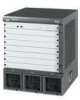
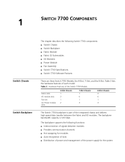
... of power and management of each model. Table 3 Hardware Features of the Switch 7700 Models Fabric slots I /O Modules ■ Power Module ■ Fan Assembly ■ Switch 7700 Specifications ■ Switch 7700 Software Features There are three Switch 7700 Models, the 4-Slot, 7-Slot, and the 8-Slot. 1 SWITCH 7700 COMPONENTS Switch Chassis Switch Backplane The chapter describes the following functions: ■ Interconnection of signals between...
... of power and management of each model. Table 3 Hardware Features of the Switch 7700 Models Fabric slots I /O Modules ■ Power Module ■ Fan Assembly ■ Switch 7700 Specifications ■ Switch 7700 Software Features There are three Switch 7700 Models, the 4-Slot, 7-Slot, and the 8-Slot. 1 SWITCH 7700 COMPONENTS Switch Chassis Switch Backplane The chapter describes the following functions: ■ Interconnection of signals between...

Installation Guide
Page 10
... functions: ■ Connects the I /O module LEDs 56 7 Figure 2 illustrates the front panel of Switch 7700 system. 10 CHAPTER 1: SWITCH 7700 COMPONENTS Fabric Module There are two Fabric modules for the Switch 7700: ■ Fabric 64 (3C16857 or 3C16857R) ■ Fabric 32 (3C16872) The Fabric 64 and ...Fabric 32 are not interchangeable. or 8-slot chassis The Fabric module is the core of the Fabric 32. Figure 2 Fabric 32 3C16872 ...
... functions: ■ Connects the I /O module LEDs 56 7 Figure 2 illustrates the front panel of Switch 7700 system. 10 CHAPTER 1: SWITCH 7700 COMPONENTS Fabric Module There are two Fabric modules for the Switch 7700: ■ Fabric 64 (3C16857 or 3C16857R) ■ Fabric 32 (3C16872) The Fabric 64 and ...Fabric 32 are not interchangeable. or 8-slot chassis The Fabric module is the core of the Fabric 32. Figure 2 Fabric 32 3C16872 ...
Installation Guide
Page 24
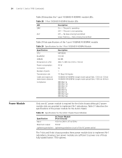
... Hz Maximum output 350 W Lightening protection Lightening protection circuit of these fully loaded Switch 7700 systems. Table 30 Specifications for the 4-Slot Chassis Power Modules Specification AC Power Module (4-slot chassis) Input 100 V to 240 V, 47 to implement N+1 redundancy. 24 CHAPTER 1: SWITCH 7700 COMPONENTS Power Module Table 28 describes the 1-port 10GBASE-R-XENPAK module LEDs. Data...
... Hz Maximum output 350 W Lightening protection Lightening protection circuit of these fully loaded Switch 7700 systems. Table 30 Specifications for the 4-Slot Chassis Power Modules Specification AC Power Module (4-slot chassis) Input 100 V to 240 V, 47 to implement N+1 redundancy. 24 CHAPTER 1: SWITCH 7700 COMPONENTS Power Module Table 28 describes the 1-port 10GBASE-R-XENPAK module LEDs. Data...

Installation Guide
Page 25
... V 460 W 2 lightening protectors in the DC power distributing box The Switch 7700 power distribution box is installed on the right side of the chassis: ■ 4-slot chassis - 3C16871 ■ 7-slot chassis - 3C16856 ■ 8-slot chassis - 3C16855 The fans are two models of the chassis. and 8-slot chassis also supports single- and dual-cord AC power module The dual...
... V 460 W 2 lightening protectors in the DC power distributing box The Switch 7700 power distribution box is installed on the right side of the chassis: ■ 4-slot chassis - 3C16871 ■ 7-slot chassis - 3C16856 ■ 8-slot chassis - 3C16855 The fans are two models of the chassis. and 8-slot chassis also supports single- and dual-cord AC power module The dual...

Installation Guide
Page 26
26 CHAPTER 1: SWITCH 7700 COMPONENTS Figure 19 Fan Assembly Switch 7700 Specifications Table 32 provides detailed information about features of the Switch 7700. Table 32 Specifications for the Switch 7700 System Item 4-Slot Chassis 7-Slot Chassis 8-Slot Chassis Dimensions (W x H x D) 436 x 352.8 x 480 mm 436 x 486.2 x 480 mm 436 x 530.6 x 480 mm (17 x 14 ...100BASE-FX MMF FE Module 20-Port 10/100/1000BASE-T Module 20-Port 1000BASE-X-SFP Module 1-port 10GBASE-R-XENPAK Module System switching 32 Gbps 64 Gbps Packet processing 24 Mpps 48 Mpps Input voltage AC: 100 V to 240 V, AC: 100 ...
26 CHAPTER 1: SWITCH 7700 COMPONENTS Figure 19 Fan Assembly Switch 7700 Specifications Table 32 provides detailed information about features of the Switch 7700. Table 32 Specifications for the Switch 7700 System Item 4-Slot Chassis 7-Slot Chassis 8-Slot Chassis Dimensions (W x H x D) 436 x 352.8 x 480 mm 436 x 486.2 x 480 mm 436 x 530.6 x 480 mm (17 x 14 ...100BASE-FX MMF FE Module 20-Port 10/100/1000BASE-T Module 20-Port 1000BASE-X-SFP Module 1-port 10GBASE-R-XENPAK Module System switching 32 Gbps 64 Gbps Packet processing 24 Mpps 48 Mpps Input voltage AC: 100 V to 240 V, AC: 100 ...

Installation Guide
Page 29
... Chassis ■ Installing the Cabling Rack ■ Installing a Module ■ Installing a Submodule ■ Connecting the Ground Wire ■ Connecting and Configuring Power ■ Installing the Fan Assembly ■ Installing Cables ■ Connecting Module Cables ■ Post-installation Checklist WARNING: Only trained and qualified personnel should install and maintain 3Com products. 2 INSTALLING THE SWITCH 7700...
... Chassis ■ Installing the Cabling Rack ■ Installing a Module ■ Installing a Submodule ■ Connecting the Ground Wire ■ Connecting and Configuring Power ■ Installing the Fan Assembly ■ Installing Cables ■ Connecting Module Cables ■ Post-installation Checklist WARNING: Only trained and qualified personnel should install and maintain 3Com products. 2 INSTALLING THE SWITCH 7700...

Installation Guide
Page 30
...safety information and special safety instructions provided by 3Com. 3Com bears no responsibility for your switch should meet the requirements described in the event of an accident. ■ Unplug all external cables (including power cord) before moving the chassis. ■ Never assume that an optical connector...cables before lifting or moving the Switch 7700. Always check. Moving the Switch Use caution when moving the chassis. ■ Do not hold the power handles when carrying the switch. ■ Do not put fingers into the vent of the entire chassis, using them to prolong the ...
...safety information and special safety instructions provided by 3Com. 3Com bears no responsibility for your switch should meet the requirements described in the event of an accident. ■ Unplug all external cables (including power cord) before moving the chassis. ■ Never assume that an optical connector...cables before lifting or moving the Switch 7700. Always check. Moving the Switch Use caution when moving the chassis. ■ Do not hold the power handles when carrying the switch. ■ Do not put fingers into the vent of the entire chassis, using them to prolong the ...

Installation Guide
Page 31
... by the static electricity, ensure that you keep the front and back of the switch more than 1 meter (3 feet) away from the walls or other external line. ■ Ensure that the PGND wire of the chassis is well grounded ■ Ensure that the neutral point of the socket of AC... at the input end of the power supply Installation Space The Switch 7700 is a complex piece of equipment so it is installed, the clear height of room should be more than 3 meters (10 ft). For better heat dissipation and equipment maintenance, 3Com recommends that : ■ The equipment is grounded ■ The ...
... by the static electricity, ensure that you keep the front and back of the switch more than 1 meter (3 feet) away from the walls or other external line. ■ Ensure that the PGND wire of the chassis is well grounded ■ Ensure that the neutral point of the socket of AC... at the input end of the power supply Installation Space The Switch 7700 is a complex piece of equipment so it is installed, the clear height of room should be more than 3 meters (10 ft). For better heat dissipation and equipment maintenance, 3Com recommends that : ■ The equipment is grounded ■ The ...

Installation Guide
Page 32
... install the cabling rack: 1 Attach the rack brace to the left side of the chassis (opposite the fan frame). 2 Insert the wiring channel into the cabinet. 3 Fix the switch in the cabinet with the switch. 32 CHAPTER 2: INSTALLING THE SWITCH 7700 ■ Tools ■ Phillips screwdriver ■ Flat-head screwdriver ■ Antistatic wrist strap ■...
... install the cabling rack: 1 Attach the rack brace to the left side of the chassis (opposite the fan frame). 2 Insert the wiring channel into the cabinet. 3 Fix the switch in the cabinet with the switch. 32 CHAPTER 2: INSTALLING THE SWITCH 7700 ■ Tools ■ Phillips screwdriver ■ Flat-head screwdriver ■ Antistatic wrist strap ■...

Installation Guide
Page 34
... power modules with either AC or DC power modules. In addition, the 8-slot chassis is available with one or two power cords. or 8-slot chassis. 34 CHAPTER 2: INSTALLING THE SWITCH 7700 Connecting the Ground Wire To connect the ground wire: 1 Wear an antistatic wrist strap. 2 Remove the screw from the ...cabinet. Connect the strip to the power source in a cabinet, 3Com recommends that the ground wire of the switch be connected to the power cord plug. 3 Plug the other end of the ground wire to the grounding bar of the switch. Figure 20 Single Power Cord Connection 12 3 1 AC power ...
... power modules with either AC or DC power modules. In addition, the 8-slot chassis is available with one or two power cords. or 8-slot chassis. 34 CHAPTER 2: INSTALLING THE SWITCH 7700 Connecting the Ground Wire To connect the ground wire: 1 Wear an antistatic wrist strap. 2 Remove the screw from the ...cabinet. Connect the strip to the power source in a cabinet, 3Com recommends that the ground wire of the switch be connected to the power cord plug. 3 Plug the other end of the ground wire to the grounding bar of the switch. Figure 20 Single Power Cord Connection 12 3 1 AC power ...

Installation Guide
Page 36
... port. 2 Connect the DB-25 or DB-9 end of the AUX cable to a modem in the chassis. Connecting the AUX An AUX cable is used to connect the Switch 7700 to the serial port of the product labelled Dangerous Voltage. Always wear the antistatic wrist strap when installing the fan. To...hole connector and a DB-25-hole connector for connection to a 9-hole or 25-hole serial port at the console port. 36 CHAPTER 2: INSTALLING THE SWITCH 7700 Installing the Fan Assembly To install the fan: 1 Wear an antistatic wrist strap. 2 Remove the fan frame from the pack. 3 Hold the ejector levers...
... port. 2 Connect the DB-25 or DB-9 end of the AUX cable to a modem in the chassis. Connecting the AUX An AUX cable is used to connect the Switch 7700 to the serial port of the product labelled Dangerous Voltage. Always wear the antistatic wrist strap when installing the fan. To...hole connector and a DB-25-hole connector for connection to a 9-hole or 25-hole serial port at the console port. 36 CHAPTER 2: INSTALLING THE SWITCH 7700 Installing the Fan Assembly To install the fan: 1 Wear an antistatic wrist strap. 2 Remove the fan frame from the pack. 3 Hold the ejector levers...

Installation Guide
Page 38
...RJ fiber connector: 1 Plug the MT-RJ fiber connector in a cabinet. Installing Cabling This section describes how to install and bind cables for your chassis on a bench, all the transit data signal cable connectors and locate them . ■ The cable body cannot be fastened securely. ■ ... should be smooth. ■ The hole through which a cable runs through should not be smooth or have installed your Switch 7700. 38 CHAPTER 2: INSTALLING THE SWITCH 7700 CAUTION: When connecting an SC fiber connector, the switch TX must be connected to the RX of the device on the network, and the...
...RJ fiber connector: 1 Plug the MT-RJ fiber connector in a cabinet. Installing Cabling This section describes how to install and bind cables for your chassis on a bench, all the transit data signal cable connectors and locate them . ■ The cable body cannot be fastened securely. ■ ... should be smooth. ■ The hole through which a cable runs through should not be smooth or have installed your Switch 7700. 38 CHAPTER 2: INSTALLING THE SWITCH 7700 CAUTION: When connecting an SC fiber connector, the switch TX must be connected to the RX of the device on the network, and the...
Installation Guide
Page 47
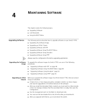
...Passwords ■ Using the BOOT Menu Upgrading Software The following sections describe how to upgrade software on your Switch 7700: ■ Upgrading the Software Image ■ Upgrading an 8-Slot Chassis ■ Upgrading Software with FTP" on page 48 ■ "Upgrading Software Using The BOOT Menu"page ...Software Using TFTP" page 55 Upgrading an 8-Slot Chassis Before you upgrade the software image of an 8-slot Switch 7700, there are several things to remember: ■ A Fabric from a 7-slot chassis should be installed in Slot0 in an 8-slot chassis and must be upgraded to V3.0 (8-slot ...
...Passwords ■ Using the BOOT Menu Upgrading Software The following sections describe how to upgrade software on your Switch 7700: ■ Upgrading the Software Image ■ Upgrading an 8-Slot Chassis ■ Upgrading Software with FTP" on page 48 ■ "Upgrading Software Using The BOOT Menu"page ...Software Using TFTP" page 55 Upgrading an 8-Slot Chassis Before you upgrade the software image of an 8-slot Switch 7700, there are several things to remember: ■ A Fabric from a 7-slot chassis should be installed in Slot0 in an 8-slot chassis and must be upgraded to V3.0 (8-slot ...

Installation Guide
Page 57
...dual-power cord module. Installing the AC Power To install the new power module, do the following: Module 1 Power off the Switch 7700. 2 Remove the power cord from the chassis. Replacing a Power Module The single-cord power module in the 7- Removing the AC Power To remove the power module, do the... power module into the power module slot in the bottom rear of the chassis. 2 Insert and tighten the 4 screws at the corners of the Switch 7700 can be performed by trained service personnel only. and 8-slot AC chassis of the power module. 6 Remove the power module from both the power...
...dual-power cord module. Installing the AC Power To install the new power module, do the following: Module 1 Power off the Switch 7700. 2 Remove the power cord from the chassis. Replacing a Power Module The single-cord power module in the 7- Removing the AC Power To remove the power module, do the... power module into the power module slot in the bottom rear of the chassis. 2 Insert and tighten the 4 screws at the corners of the Switch 7700 can be performed by trained service personnel only. and 8-slot AC chassis of the power module. 6 Remove the power module from both the power...

Installation Guide
Page 59
... hold the ejector levers on the module that contained the replacement module. Replacing the Fan Assembly You can hot-swap fan assemblies in the chassis. 4 Fasten the captive screws to separate the connectors of the module from the backplane. 3 Pull the fan gently along the guides of... from the motherboard. 4 Gently slide the module along the guides and out of the slot. 5 Put the removed module into the positioning hole in the Switch 7700. Replacing I /O module, you need : ■ An antistatic wrist strap ■ A Screwdriver WARNING: To avoid injury, do not touch any naked wire,...
... hold the ejector levers on the module that contained the replacement module. Replacing the Fan Assembly You can hot-swap fan assemblies in the chassis. 4 Fasten the captive screws to separate the connectors of the module from the backplane. 3 Pull the fan gently along the guides of... from the motherboard. 4 Gently slide the module along the guides and out of the slot. 5 Put the removed module into the positioning hole in the Switch 7700. Replacing I /O module, you need : ■ An antistatic wrist strap ■ A Screwdriver WARNING: To avoid injury, do not touch any naked wire,...

Installation Guide
Page 60
Failure to overheat. Align it gently into the slot until you feel the positioning pin on the handle bar touch the hole in the chassis. 5 Press the ejector levers inward and seat the pin on the handle bar into the positioning hole in the chassis. WARNING: If the fan fails, replace it with the guides in the chassis and slide it with a new one without delay before operating the Switch 7700. 60 CHAPTER 5: MAINTAINING HARDWARE 4 With both hands, pull out the ejector levers of the fan that will cause the switch to do so will be installed.
Failure to overheat. Align it gently into the slot until you feel the positioning pin on the handle bar touch the hole in the chassis. 5 Press the ejector levers inward and seat the pin on the handle bar into the positioning hole in the chassis. WARNING: If the fan fails, replace it with the guides in the chassis and slide it with a new one without delay before operating the Switch 7700. 60 CHAPTER 5: MAINTAINING HARDWARE 4 With both hands, pull out the ejector levers of the fan that will cause the switch to do so will be installed.