Installation Guide
Page 3
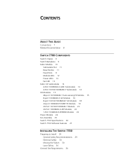
CONTENTS ABOUT THIS GUIDE Conventions 7 Related Documentation 8 SWITCH 7700 COMPONENTS Switch Chassis 9 Switch Backplane 9 Fabric Module 10 Submodule Slot 11 Reset Button 11 Fixed Ports 11 Module LEDs 12 Power LEDs 13 Fan LED 13 Fabric 32 Submodules ... 19 20-Port 10/100/1000BASE-T Module 20 20-Port 1000BASE-X-SFP Module 22 1-Port 10GBASE-R-XENPAK Module 23 Power Module 24 Fan Assembly 25 Switch 7700 Specifications 26 Switch 7700 Software Features 27 INSTALLING THE SWITCH 7700 Preparing to Install 29 General Safety Recommendations 29 Electrical Safety 30 Moving the...
CONTENTS ABOUT THIS GUIDE Conventions 7 Related Documentation 8 SWITCH 7700 COMPONENTS Switch Chassis 9 Switch Backplane 9 Fabric Module 10 Submodule Slot 11 Reset Button 11 Fixed Ports 11 Module LEDs 12 Power LEDs 13 Fan LED 13 Fabric 32 Submodules ... 19 20-Port 10/100/1000BASE-T Module 20 20-Port 1000BASE-X-SFP Module 22 1-Port 10GBASE-R-XENPAK Module 23 Power Module 24 Fan Assembly 25 Switch 7700 Specifications 26 Switch 7700 Software Features 27 INSTALLING THE SWITCH 7700 Preparing to Install 29 General Safety Recommendations 29 Electrical Safety 30 Moving the...
Installation Guide
Page 9
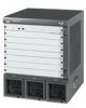
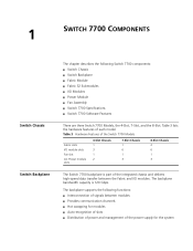
...; Fabric Module ■ Fabric 32 Submodules ■ I /O modules. 1 SWITCH 7700 COMPONENTS Switch Chassis Switch Backplane The chapter describes the following functions: ■ Interconnection of signals between the Fabric and I /O Modules ■ Power Module ■ Fan Assembly ■ Switch 7700 Specifications ■ Switch 7700 Software Features There are three Switch 7700 Models, the 4-Slot, 7-Slot, and the 8-Slot...
...; Fabric Module ■ Fabric 32 Submodules ■ I /O modules. 1 SWITCH 7700 COMPONENTS Switch Chassis Switch Backplane The chapter describes the following functions: ■ Interconnection of signals between the Fabric and I /O Modules ■ Power Module ■ Fan Assembly ■ Switch 7700 Specifications ■ Switch 7700 Software Features There are three Switch 7700 Models, the 4-Slot, 7-Slot, and the 8-Slot...
Installation Guide
Page 11
...Switch 7700 Fabric module provides the following submodules: ■ 4-port 1000BASE-X-GBIC submodule ■ 4-port 10/100/1000BASE-T submodule For more information on these submodules, see "Fabric 32 Submodules"on the console port. You can configure the baud rate on page 13. Table 5 Console Port Specifications Specification... Port connector Port standard Description RJ-45 Asynchronous EIA/TIA-232 Fabric Module 11 Table 4 lists Fabric specifications. Table 4 Fabric Specifications Item Fabric 64 (3C16857 or 3C16857R...
...Switch 7700 Fabric module provides the following submodules: ■ 4-port 1000BASE-X-GBIC submodule ■ 4-port 10/100/1000BASE-T submodule For more information on these submodules, see "Fabric 32 Submodules"on the console port. You can configure the baud rate on page 13. Table 5 Console Port Specifications Specification... Port connector Port standard Description RJ-45 Asynchronous EIA/TIA-232 Fabric Module 11 Table 4 lists Fabric specifications. Table 4 Fabric Specifications Item Fabric 64 (3C16857 or 3C16857R...

Installation Guide
Page 12
... using an RJ-45 connector. The Ethernet port can use the Ethernet port for system application downloading and debugging. Green - 12 CHAPTER 1: SWITCH 7700 COMPONENTS Table 5 Console Port Specifications (continued) Specification Baud rate Transmission distance Services Description 9600 bps (by default) 15 m (45 ft) Connects with character terminal Connects with local or remote...
... using an RJ-45 connector. The Ethernet port can use the Ethernet port for system application downloading and debugging. Green - 12 CHAPTER 1: SWITCH 7700 COMPONENTS Table 5 Console Port Specifications (continued) Specification Baud rate Transmission distance Services Description 9600 bps (by default) 15 m (45 ft) Connects with character terminal Connects with local or remote...
Installation Guide
Page 14
...Off - The link is operating normally. No data is being transmitted. Data is being transmitted. Table 12 4-Port 1000BASE-X-GBIC Submodule Specifications Optional GBIC Module 1000BASE-SX-MM (3CGBIC91) Central Wavelength 850 nm 1000BASE-LX-SM-IR 1310 nm (3CGBIC92) 1000BASE-LX-SM (...fiber Max. Figure 4 illustrates the 4-port 10/100/1000BASE-T submodule. The link is not operating. 14 CHAPTER 1: SWITCH 7700 COMPONENTS Table 12 lists the specifications for each of ports Port speed Cable and maximum transmission distance Description RJ-45 4 1000 Mbps full duplex 100 Mbps half...
...Off - The link is operating normally. No data is being transmitted. Data is being transmitted. Table 12 4-Port 1000BASE-X-GBIC Submodule Specifications Optional GBIC Module 1000BASE-SX-MM (3CGBIC91) Central Wavelength 850 nm 1000BASE-LX-SM-IR 1310 nm (3CGBIC92) 1000BASE-LX-SM (...fiber Max. Figure 4 illustrates the 4-port 10/100/1000BASE-T submodule. The link is not operating. 14 CHAPTER 1: SWITCH 7700 COMPONENTS Table 12 lists the specifications for each of ports Port speed Cable and maximum transmission distance Description RJ-45 4 1000 Mbps full duplex 100 Mbps half...

Installation Guide
Page 16
... GE module provides 8 external GBIC module ports. A GBIC module is connected Off - The port is being transmitted Table 16 describes the specifications of ports Port transmission speed Cables and maximum transmission distance Compliance Description MPC850 512 KB 64 MB 366.7 x 340 mm (14.5 x ... ■ 3CGBIC92 ■ 3CGBIC97 Figure 7 illustrates the 8-port 1000BASE-X GE module. Data is not connected Green flashing - 16 CHAPTER 1: SWITCH 7700 COMPONENTS 1 Ethernet port 2 Ethernet port LED Each 100 Mbps Ethernet port has a green LED, indicating LINK/ACTIVE status. IEEE802.3 IEEE802....
... GE module provides 8 external GBIC module ports. A GBIC module is connected Off - The port is being transmitted Table 16 describes the specifications of ports Port transmission speed Cables and maximum transmission distance Compliance Description MPC850 512 KB 64 MB 366.7 x 340 mm (14.5 x ... ■ 3CGBIC92 ■ 3CGBIC97 Figure 7 illustrates the 8-port 1000BASE-X GE module. Data is not connected Green flashing - 16 CHAPTER 1: SWITCH 7700 COMPONENTS 1 Ethernet port 2 Ethernet port LED Each 100 Mbps Ethernet port has a green LED, indicating LINK/ACTIVE status. IEEE802.3 IEEE802....

Installation Guide
Page 17
... - Figure 7 8-Port 1000BASE-X GE Module I/O Modules 17 3C16858 Every GBIC port has a LED, as shown in Figure 8. Table 19 Specifications for each of the supported 8GBIC modules are described inTable 18. Table 18 GBIC Module Port Cables GBIC Module Type 3CGBIC91 3CGBIC92 3CGBIC97 Central Wave ...Length 850 nm 1550 nm 1550 nm Table 19 describes the specifications of the 8-Port 1000BASE-X GE Module 12 1 GBIC port 2 GBIC port LED Table 17 describes the 8-Port 1000BASE-X (GBIC) GE ...
... - Figure 7 8-Port 1000BASE-X GE Module I/O Modules 17 3C16858 Every GBIC port has a LED, as shown in Figure 8. Table 19 Specifications for each of the supported 8GBIC modules are described inTable 18. Table 18 GBIC Module Port Cables GBIC Module Type 3CGBIC91 3CGBIC92 3CGBIC97 Central Wave ...Length 850 nm 1550 nm 1550 nm Table 19 describes the specifications of the 8-Port 1000BASE-X GE Module 12 1 GBIC port 2 GBIC port LED Table 17 describes the 8-Port 1000BASE-X (GBIC) GE ...

Installation Guide
Page 18
... 366.7 x 340 mm (14.5 x 13.4 in Figure 10. Figure 9 illustrates the 8-port 10/100/1000BASE-T GE module. 18 CHAPTER 1: SWITCH 7700 COMPONENTS Table 19 Specifications for the 8-Port 1000BASE-X GE Module (continued) Specification BootROM SDRAM Dimensions (L x W) Maximum power consumption Number of the 8-Port 10/100/1000BASE-T GE Module 12 1 Ethernet port 2 Ethernet port...
... 366.7 x 340 mm (14.5 x 13.4 in Figure 10. Figure 9 illustrates the 8-port 10/100/1000BASE-T GE module. 18 CHAPTER 1: SWITCH 7700 COMPONENTS Table 19 Specifications for the 8-Port 1000BASE-X GE Module (continued) Specification BootROM SDRAM Dimensions (L x W) Maximum power consumption Number of the 8-Port 10/100/1000BASE-T GE Module 12 1 Ethernet port 2 Ethernet port...

Installation Guide
Page 19
No data is connected ACT Off - Figure 11 illustrates the 24-port 100BASE-FX MMF FE module. Table 21 Specifications for the 8-Port 10/100/1000BASE-T GE Module Specification Description CPU MPC850 BootROM 512 Kb SDRAM 64 MB Dimensions (L x W) 366.7 x 340 mm (14.5 x 13.4 in) Maximum power ...type RJ-45 Number of the 8-port 10/100/1000BASE-T GE module are described in Table 21. The link is being transmitted or received Specifications of ports 8 Port transmission speed 10 Mbps, half/full duplex 100 Mbps, half/full duplex 1000 Mbps, full duplex Cables and maximum ...
No data is connected ACT Off - Figure 11 illustrates the 24-port 100BASE-FX MMF FE module. Table 21 Specifications for the 8-Port 10/100/1000BASE-T GE Module Specification Description CPU MPC850 BootROM 512 Kb SDRAM 64 MB Dimensions (L x W) 366.7 x 340 mm (14.5 x 13.4 in) Maximum power ...type RJ-45 Number of the 8-port 10/100/1000BASE-T GE module are described in Table 21. The link is being transmitted or received Specifications of ports 8 Port transmission speed 10 Mbps, half/full duplex 100 Mbps, half/full duplex 1000 Mbps, full duplex Cables and maximum ...

Installation Guide
Page 20
... LEDs LED LINK/ACT Description Green - Off - Data is connected. The port is being transmitted or received. Green flashing - Table 23 describes the specifications of ports Port transmission speed Cables and maximum transmission distance Compliance Description MPC850 512 KB 64 MB 366.7 x 340 mm (14.5 x 13.4 in ...Figure 12. Figure 13 illustrates the 20-Port 10/100/1000BASE-T Module. The port is not connected. 20 CHAPTER 1: SWITCH 7700 COMPONENTS Each 100 Mbps optical port has a green LED, as shown in ) 55 W MT-RJ 24 100 Mbps, full-duplex 62.5/125 µm ...
... LEDs LED LINK/ACT Description Green - Off - Data is connected. The port is being transmitted or received. Green flashing - Table 23 describes the specifications of ports Port transmission speed Cables and maximum transmission distance Compliance Description MPC850 512 KB 64 MB 366.7 x 340 mm (14.5 x 13.4 in ...Figure 12. Figure 13 illustrates the 20-Port 10/100/1000BASE-T Module. The port is not connected. 20 CHAPTER 1: SWITCH 7700 COMPONENTS Each 100 Mbps optical port has a green LED, as shown in ) 55 W MT-RJ 24 100 Mbps, full-duplex 62.5/125 µm ...

Installation Guide
Page 21
... 10 Mbps half/full duplex 100 Mbps half/full duplex 1000 Mbps full duplex The port is not operating. Table 25 Specifications for the 20-Port 10/100/1000BASE-T Module Specification CPU BootROM SDRAM Dimensions (L x W) Power consumption Connector Number of the 20-Port 10/100/1000BASE-T Module 3C16863 12 1 Ethernet port 2 Ethernet.... Table 24 20-Port 10/100/1000BASE-T Module LEDs LED LINK/ACT Description Off - On - Green flashing - The port is transmitting data Table 25 lists specifications of the 20-port 10/100/1000BASE-T module. The port is operating.
... 10 Mbps half/full duplex 100 Mbps half/full duplex 1000 Mbps full duplex The port is not operating. Table 25 Specifications for the 20-Port 10/100/1000BASE-T Module Specification CPU BootROM SDRAM Dimensions (L x W) Power consumption Connector Number of the 20-Port 10/100/1000BASE-T Module 3C16863 12 1 Ethernet port 2 Ethernet.... Table 24 20-Port 10/100/1000BASE-T Module LEDs LED LINK/ACT Description Off - On - Green flashing - The port is transmitting data Table 25 lists specifications of the 20-port 10/100/1000BASE-T module. The port is operating.

Installation Guide
Page 22
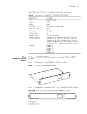
... transmitting data The port is operating. Figure 16 Front Panel of the 20-port 1000BASE-X-SFP module. 22 CHAPTER 1: SWITCH 7700 COMPONENTS Table 25 Specifications for the 20-Port 10/100/1000BASE-T Module (continued) Specification Cable and maximum transmission distance Compliance Description Category-5 twisted pair 100 m (300 ft) IEEE 802.3ab IEEE 802...
... transmitting data The port is operating. Figure 16 Front Panel of the 20-port 1000BASE-X-SFP module. 22 CHAPTER 1: SWITCH 7700 COMPONENTS Table 25 Specifications for the 20-Port 10/100/1000BASE-T Module (continued) Specification Cable and maximum transmission distance Compliance Description Category-5 twisted pair 100 m (300 ft) IEEE 802.3ab IEEE 802...
Installation Guide
Page 23
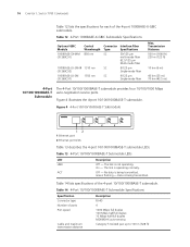
... the 20-Port 1000BASE-X-SFP Module Specification CPU BootROM SDRAM Dimensions (L x W) Power consumption Connector Number of the 1-Port 10GBASE-R-XENPAK Module 3C16875 1 XENPAK port 2 XENPAK port LEDs 1 2 Figure 18 Front Panel of .... Figure 17 1-Port 10GBASE-R-XENPAK Module 3C16875 Figure 18 illustrates the front panel of the 20-port 1000BASE-X-SFP module. I/O Modules 23 Table 27 lists specifications of the 1-port 10GBASE-R-XENPAK module.
... the 20-Port 1000BASE-X-SFP Module Specification CPU BootROM SDRAM Dimensions (L x W) Power consumption Connector Number of the 1-Port 10GBASE-R-XENPAK Module 3C16875 1 XENPAK port 2 XENPAK port LEDs 1 2 Figure 18 Front Panel of .... Figure 17 1-Port 10GBASE-R-XENPAK Module 3C16875 Figure 18 illustrates the front panel of the 20-port 1000BASE-X-SFP module. I/O Modules 23 Table 27 lists specifications of the 1-port 10GBASE-R-XENPAK module.
Installation Guide
Page 24
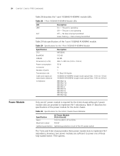
... the 4-Slot Chassis Power Modules Specification AC Power Module (4-slot chassis) Input 100 V to 240 V, 47 to 63 Hz Maximum output 350 W Lightening protection Lightening protection circuit of the 1-port 10GBASE-R-XENPAK module. 24 CHAPTER 1: SWITCH 7700 COMPONENTS Power Module Table 28... describes the 1-port 10GBASE-R-XENPAK module LEDs. No data is not operating ACT Off - The port is operating Off - Table 30 Specifications for the 4-slot chassis.
... the 4-Slot Chassis Power Modules Specification AC Power Module (4-slot chassis) Input 100 V to 240 V, 47 to 63 Hz Maximum output 350 W Lightening protection Lightening protection circuit of the 1-port 10GBASE-R-XENPAK module. 24 CHAPTER 1: SWITCH 7700 COMPONENTS Power Module Table 28... describes the 1-port 10GBASE-R-XENPAK module LEDs. No data is not operating ACT Off - The port is operating Off - Table 30 Specifications for the 4-slot chassis.

Installation Guide
Page 25
... connectors. and dual-cord AC power module The dual-cord power module is installed on the right side of power module. Table 31 describes the specifications of each type of the chassis: ■ 4-slot chassis - 3C16871 ■ 7-slot chassis - 3C16856 ■ 8-slot chassis - 3C16855 ...The fans are collected and transmitted to -60 V 460 W 2 lightening protectors in the DC power distributing box The Switch 7700 power distribution box is available in the back of the 8-slot chassis that offer either AC or DC power modules. It controls current connection...
... connectors. and dual-cord AC power module The dual-cord power module is installed on the right side of power module. Table 31 describes the specifications of each type of the chassis: ■ 4-slot chassis - 3C16871 ■ 7-slot chassis - 3C16856 ■ 8-slot chassis - 3C16855 ...The fans are collected and transmitted to -60 V 460 W 2 lightening protectors in the DC power distributing box The Switch 7700 power distribution box is available in the back of the 8-slot chassis that offer either AC or DC power modules. It controls current connection...

Installation Guide
Page 26
Table 32 Specifications for the Switch 7700 System Item 4-Slot Chassis 7-Slot Chassis 8-Slot Chassis Dimensions (W x H x D) 436 x 352.8 x 480 mm ... MMF FE Module 20-Port 10/100/1000BASE-T Module 20-Port 1000BASE-X-SFP Module 1-port 10GBASE-R-XENPAK Module System switching 32 Gbps 64 Gbps Packet processing 24 Mpps 48 Mpps Input voltage AC: 100 V to 240 V, AC: ... temperature and humidity 0 to 40 0 C (32 to 104 0 F) and 5% to 85% 26 CHAPTER 1: SWITCH 7700 COMPONENTS Figure 19 Fan Assembly Switch 7700 Specifications Table 32 provides detailed information about features of the...
Table 32 Specifications for the Switch 7700 System Item 4-Slot Chassis 7-Slot Chassis 8-Slot Chassis Dimensions (W x H x D) 436 x 352.8 x 480 mm ... MMF FE Module 20-Port 10/100/1000BASE-T Module 20-Port 1000BASE-X-SFP Module 1-port 10GBASE-R-XENPAK Module System switching 32 Gbps 64 Gbps Packet processing 24 Mpps 48 Mpps Input voltage AC: 100 V to 240 V, AC: ... temperature and humidity 0 to 40 0 C (32 to 104 0 F) and 5% to 85% 26 CHAPTER 1: SWITCH 7700 COMPONENTS Figure 19 Fan Assembly Switch 7700 Specifications Table 32 provides detailed information about features of the...