
User Manual
Page 2
... LEGEND If you are a United States government agency, then this product is a trademark of Sun Microsystems. All other countries. 3Com and the 3Com logo are vegetable-based with only such rights as such is the policy of Netscape Communications. Microsoft, MS-DOS, Windows, and...and the software described herein are provided to you subject to you are labelled according to recognized environmental standards. Regulated Materials Statement 3Com products do not contain any software on a continual basis. ENVIRONMENTAL STATEMENT It is provided with a low heavy-metal content. ...
... LEGEND If you are a United States government agency, then this product is a trademark of Sun Microsystems. All other countries. 3Com and the 3Com logo are vegetable-based with only such rights as such is the policy of Netscape Communications. Microsoft, MS-DOS, Windows, and...and the software described herein are provided to you subject to you are labelled according to recognized environmental standards. Regulated Materials Statement 3Com products do not contain any software on a continual basis. ENVIRONMENTAL STATEMENT It is provided with a low heavy-metal content. ...

User Manual
Page 3
... 1 INTRODUCING THE BASELINE SWITCH Overview of the Baseline Switch 7 Features and Capabilities 7 Autosensing of MDI/MDIX Connections 7 Autonegotiating 10/100/1000 Mbps Ports 7 SFP Ports 7 Physical Features 8 Front Panel 8 Rear Panel 11 Package Contents 11 2 INSTALLING THE SWITCH Before You Begin 13 Positioning the Switch 13 Rack-Mounting or...14 Using the Mounting Kit 14 Montagesatz Anweisungen 15 Placing Units On Top of Each Other 15 Supplying Power to the Switch 16 Checking for Correct Operation 16 Connecting a Network Device 17 Using SFP Transceivers 18 Approved SFP Transceivers 18 Inserting ...
... 1 INTRODUCING THE BASELINE SWITCH Overview of the Baseline Switch 7 Features and Capabilities 7 Autosensing of MDI/MDIX Connections 7 Autonegotiating 10/100/1000 Mbps Ports 7 SFP Ports 7 Physical Features 8 Front Panel 8 Rear Panel 11 Package Contents 11 2 INSTALLING THE SWITCH Before You Begin 13 Positioning the Switch 13 Rack-Mounting or...14 Using the Mounting Kit 14 Montagesatz Anweisungen 15 Placing Units On Top of Each Other 15 Supplying Power to the Switch 16 Checking for Correct Operation 16 Connecting a Network Device 17 Using SFP Transceivers 18 Approved SFP Transceivers 18 Inserting ...

User Manual
Page 4
Changing the Admin Password 28 Modifying the IP Address Settings 29 Automatic IP Configuration 29 Setting the IP Address 30 Configuring Port Settings 31 Basic Port Configuration 31 Advanced Port Configuration 33 Configuring VLANs 33 Creating a VLAN 34 Sample VLAN Configurations 35 Removing a VLAN 37 Configuring Link Aggregation 37 Guidelines for Creating Aggregated Links 38 Defining the Members of an Aggregated Link 38 Modifying Settings and Deleting an Aggregated Link 39 Viewing the Trunk Summary 39 Viewing Statistics 40 Mirroring Port Traffic 41 Running Cable Diagnostic 42 Using the System ...
Changing the Admin Password 28 Modifying the IP Address Settings 29 Automatic IP Configuration 29 Setting the IP Address 30 Configuring Port Settings 31 Basic Port Configuration 31 Advanced Port Configuration 33 Configuring VLANs 33 Creating a VLAN 34 Sample VLAN Configurations 35 Removing a VLAN 37 Configuring Link Aggregation 37 Guidelines for Creating Aggregated Links 38 Defining the Members of an Aggregated Link 38 Modifying Settings and Deleting an Aggregated Link 39 Viewing the Trunk Summary 39 Viewing Statistics 40 Mirroring Port Traffic 41 Running Cable Diagnostic 42 Using the System ...

User Manual
Page 5
... information in Adobe Acrobat Reader Portable Document Format (PDF) on the 3Com World Wide Web site: www.3com.com Naming Convention Throughout this guide, the 3Com Baseline Switch 2816/2824-SFP Plus is referred to as the Switch. If a release note is intended for use by those responsible for... installing and setting up network equipment. Category 3 and Category 5 Twisted Pair Cables are linked with this 3Com Baseline Switch 2816-SFP/2824-SFP Plus and contains information that alerts you to potential loss of local area networks (LANs). Keyboard key names If you...
... information in Adobe Acrobat Reader Portable Document Format (PDF) on the 3Com World Wide Web site: www.3com.com Naming Convention Throughout this guide, the 3Com Baseline Switch 2816/2824-SFP Plus is referred to as the Switch. If a release note is intended for use by those responsible for... installing and setting up network equipment. Category 3 and Category 5 Twisted Pair Cables are linked with this 3Com Baseline Switch 2816-SFP/2824-SFP Plus and contains information that alerts you to potential loss of local area networks (LANs). Keyboard key names If you...

User Manual
Page 6
.... Documentation Comments Your suggestions are used to -date information on page 47. Related Documentation In addition to this guide, each 3Com Baseline Switch 2816-SFP/2824-SFP Plus documentation set includes the following information when commenting: ■ Document title ■ Document part number (on the title... page) ■ Page number (if appropriate) Example: ■ 3Com Baseline Switch 2816-SFP/2824-SFP Plus User Guide ■ Part Number DUA1648-5AAA03 ■ Page 24 Do not use this document to 3Com at the place where it is defined in the text. ■ Identify...
.... Documentation Comments Your suggestions are used to -date information on page 47. Related Documentation In addition to this guide, each 3Com Baseline Switch 2816-SFP/2824-SFP Plus documentation set includes the following information when commenting: ■ Document title ■ Document part number (on the title... page) ■ Page number (if appropriate) Example: ■ 3Com Baseline Switch 2816-SFP/2824-SFP Plus User Guide ■ Part Number DUA1648-5AAA03 ■ Page 24 Do not use this document to 3Com at the place where it is defined in the text. ■ Identify...

User Manual
Page 7
... connections. Autonegotiating 10/100/1000 Mbps Ports Each 10/100/1000 Mbps port automatically determines the speed and duplex mode of the 3Com® Baseline Switch 2816/2824-SFP Plus. SFP Ports The four SFP ports support fiber Gigabit Ethernet short-wave (SX) and long-wave (LX) SFP...10/100 Mbps connections on the other hand, only operate in It also identifies the contents of the Baseline Switch The 3Com Baseline Switch 2816-SFP/2824-SFP Plus is necessary. Overview of the Switch package and helps you to connect network devices to fiber-based Gigabit media. No configuration is a ...
... connections. Autonegotiating 10/100/1000 Mbps Ports Each 10/100/1000 Mbps port automatically determines the speed and duplex mode of the 3Com® Baseline Switch 2816/2824-SFP Plus. SFP Ports The four SFP ports support fiber Gigabit Ethernet short-wave (SX) and long-wave (LX) SFP...10/100 Mbps connections on the other hand, only operate in It also identifies the contents of the Baseline Switch The 3Com Baseline Switch 2816-SFP/2824-SFP Plus is necessary. Overview of the Switch package and helps you to connect network devices to fiber-based Gigabit media. No configuration is a ...

User Manual
Page 8
... and connection operations. (1) RJ-45 10/100/1000 Ports WARNING: RJ-45 Ports. Figure 1 Front and Rear Panels (2816-SFP) 1 1 9 8 4 5 12 13 Baseline Switch 2816-SFP Plus Module Present 8 16 Link/Activity : Green = 1000M, Yellow = 10/1000M, Flash = Activity, Duplex : On = Full, Off = Half 3C16485A 2 4... in "Front Panel" below and "Rear Panel" on page 11. The Switch has 16 (2816-SFP) or 24 (2824-SFP) 10/100/1000 Mbps auto-negotiating ports. 8 CHAPTER 1: INTRODUCING THE BASELINE SWITCH any combination. The numbers in this diagram refer to these sockets. Either shielded...
... and connection operations. (1) RJ-45 10/100/1000 Ports WARNING: RJ-45 Ports. Figure 1 Front and Rear Panels (2816-SFP) 1 1 9 8 4 5 12 13 Baseline Switch 2816-SFP Plus Module Present 8 16 Link/Activity : Green = 1000M, Yellow = 10/1000M, Flash = Activity, Duplex : On = Full, Off = Half 3C16485A 2 4... in "Front Panel" below and "Rear Panel" on page 11. The Switch has 16 (2816-SFP) or 24 (2824-SFP) 10/100/1000 Mbps auto-negotiating ports. 8 CHAPTER 1: INTRODUCING THE BASELINE SWITCH any combination. The numbers in this diagram refer to these sockets. Either shielded...
User Manual
Page 9
... such a configuration, you may notice some degradation of network performance. 3Com recommends that you the flexibility of 100 full duplex mode. SFP ports are numbered 13 to 16 (2816-SFP) and 21 to 24 (2824-SFP) on the front of the Switch, and how to read their speed and duplex mode (half duplex... or full duplex for 10BASE-T and 100BASE-TX, full duplex only for 1000BASE-T, then the Switch uses the forced-mode default of using Physical Features...
... such a configuration, you may notice some degradation of network performance. 3Com recommends that you the flexibility of 100 full duplex mode. SFP ports are numbered 13 to 16 (2816-SFP) and 21 to 24 (2824-SFP) on the front of the Switch, and how to read their speed and duplex mode (half duplex... or full duplex for 10BASE-T and 100BASE-TX, full duplex only for 1000BASE-T, then the Switch uses the forced-mode default of using Physical Features...

User Manual
Page 10
...further advice. (4) Module Active LEDs The Module Active LEDs shows the status of Status LEDs, which are not swapped. Switch is in failsafe mode. 10 CHAPTER 1: INTRODUCING THE BASELINE SWITCH Table 1 10BASE-T/100BASE-TX Ports Flashing Port disabled or link loopback error. Flashing Green ■ Power-on . &#...problem, it may be that the receive (RX) and transmit (TX) cable connectors are colored yellow, show the duplex status of the Switch: Table 4 Power LEDs Status Meaning Green The unit is faulty. Yellow to Green Off The link has not been established, either nothing...
...further advice. (4) Module Active LEDs The Module Active LEDs shows the status of Status LEDs, which are not swapped. Switch is in failsafe mode. 10 CHAPTER 1: INTRODUCING THE BASELINE SWITCH Table 1 10BASE-T/100BASE-TX Ports Flashing Port disabled or link loopback error. Flashing Green ■ Power-on . &#...problem, it may be that the receive (RX) and transmit (TX) cable connectors are colored yellow, show the duplex status of the Switch: Table 4 Power LEDs Status Meaning Green The unit is faulty. Yellow to Green Off The link has not been established, either nothing...

User Manual
Page 11
...9632; Four standard height, self-adhesive rubber pads ■ One mounting kit ■ 3Com Installation CD ■ This User Guide ■ Warranty flyer If any of the lower unit. This returns the Switch to the factory default settings if, for details. Refer to be lost. Place the unit... locate with four self-adhesive rubber pads. If the unit is complete. CAUTION: 3Com recommends that your user name or password. If you have forgotten the default IP address, or forgotten your Switch package is to "Configuration" on the underside of the unit. Package Contents 11 ...
...9632; Four standard height, self-adhesive rubber pads ■ One mounting kit ■ 3Com Installation CD ■ This User Guide ■ Warranty flyer If any of the lower unit. This returns the Switch to the factory default settings if, for details. Refer to be lost. Place the unit... locate with four self-adhesive rubber pads. If the unit is complete. CAUTION: 3Com recommends that your user name or password. If you have forgotten the default IP address, or forgotten your Switch package is to "Configuration" on the underside of the unit. Package Contents 11 ...

User Manual
Page 12
12 CHAPTER 1: INTRODUCING THE BASELINE SWITCH
12 CHAPTER 1: INTRODUCING THE BASELINE SWITCH

User Manual
Page 13
... relatives à la sécurité qui se trouvent dans l'Appendice B (Appendix C) de ce guide. Positioning the Switch The Switch is suitable for use in an office environment where it can be free-standing or mounted in Appendix C of this guide. ADVERTENCIA... any maintenance procedures, read the safety information provided in a standard 19-inch equipment rack. Bevor Sie Komponenten aus dem Switch entfernen oder dem Switch hinzufuegen oder Instandhaltungsarbeiten verrichten, lesen Sie die Sicherheitsanweisungen, die in Anhang B (Appendix C) in diesem Handbuch aufgefuehrt sind. ...
... relatives à la sécurité qui se trouvent dans l'Appendice B (Appendix C) de ce guide. Positioning the Switch The Switch is suitable for use in an office environment where it can be free-standing or mounted in Appendix C of this guide. ADVERTENCIA... any maintenance procedures, read the safety information provided in a standard 19-inch equipment rack. Bevor Sie Komponenten aus dem Switch entfernen oder dem Switch hinzufuegen oder Instandhaltungsarbeiten verrichten, lesen Sie die Sicherheitsanweisungen, die in Anhang B (Appendix C) in diesem Handbuch aufgefuehrt sind. ...

User Manual
Page 14
...pads from the unit. Do not place objects on page 13. 14 CHAPTER 2: INSTALLING THE SWITCH Alternatively, the Switch can be free-standing. A mounting kit, containing two mounting brackets and four screws, is ... connected easily. ■ Cabling is away from sources of the case is not restricted (3Com recommends that the unit is 1U high and will fit in the side of electrical noise.... and through the vents in a standard 19-inch rack. It is as free of different size Baseline or Superstack® 3 units, the smaller units must be exceeded. Static discharge can interfere with two...
...pads from the unit. Do not place objects on page 13. 14 CHAPTER 2: INSTALLING THE SWITCH Alternatively, the Switch can be free-standing. A mounting kit, containing two mounting brackets and four screws, is ... connected easily. ■ Cabling is away from sources of the case is not restricted (3Com recommends that the unit is 1U high and will fit in the side of electrical noise.... and through the vents in a standard 19-inch rack. It is as free of different size Baseline or Superstack® 3 units, the smaller units must be exceeded. Static discharge can interfere with two...

User Manual
Page 16
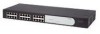
... one in the marked area at each other end of the lower unit. When POST is called "power cycling". Place the Switch units on and power off the Switch is by connecting and disconnecting the power cord. Installing proper grounding helps to power on top of each corner. Refer to avoid unforeseen... Power to earth ground during normal use Table 5 Possible Power LED Colors After POST Color State Green The unit is connected to the Switch Power problems can be grounded. To power on and ready for the Power LED after POST, it means that you power on self-test (POST)....
... one in the marked area at each other end of the lower unit. When POST is called "power cycling". Place the Switch units on and power off the Switch is by connecting and disconnecting the power cord. Installing proper grounding helps to power on top of each corner. Refer to avoid unforeseen... Power to earth ground during normal use Table 5 Possible Power LED Colors After POST Color State Green The unit is connected to the Switch Power problems can be grounded. To power on and ready for the Power LED after POST, it means that you power on self-test (POST)....

User Manual
Page 17
...the Power LED and see if POST was powered on the Switch again ■ If the Switch still does not operate, contact your 3Com network supplier If POST fails, try the following: ■ Power off the Switch, and then power it . See "Resetting to Factory ... a network device to an RJ-45 port on again. Figure 3 Connecting Devices to the Switch Baseline 10/100 Switch Endstations on switched 100 Mbps connections Baseline 10/100 Switch Endstations on switched 100 Mbps connections BaselineBSawsietclihne28S1w6i/t2ch82242-5S0FP Plus 1000 Mbps copper or F iber connection to backbone or...
...the Power LED and see if POST was powered on the Switch again ■ If the Switch still does not operate, contact your 3Com network supplier If POST fails, try the following: ■ Power off the Switch, and then power it . See "Resetting to Factory ... a network device to an RJ-45 port on again. Figure 3 Connecting Devices to the Switch Baseline 10/100 Switch Endstations on switched 100 Mbps connections Baseline 10/100 Switch Endstations on switched 100 Mbps connections BaselineBSawsietclihne28S1w6i/t2ch82242-5S0FP Plus 1000 Mbps copper or F iber connection to backbone or...

User Manual
Page 18
... from an SFP slot. Use this transceiver to connect the Switch directly to a single-mode fiber-optic cable or to power off the Switch. You can remove them into your Internet browser: www.3com.com 3Com recommends using Category 5e or 6 cables. See "Troubleshooting" starting... on the connecting device. Using SFP Transceivers The following : ■ 1000BASE-SX SFP transceiver - Use this transceiver to connect the Switch directly to the appropriate RJ-45...
... from an SFP slot. Use this transceiver to connect the Switch directly to a single-mode fiber-optic cable or to power off the Switch. You can remove them into your Internet browser: www.3com.com 3Com recommends using Category 5e or 6 cables. See "Troubleshooting" starting... on the connecting device. Using SFP Transceivers The following : ■ 1000BASE-SX SFP transceiver - Use this transceiver to connect the Switch directly to the appropriate RJ-45...

User Manual
Page 19
...to the network using a duplex LC connector. Figure 4 Inserting an SFP Transceiver Product label Wire release lever Module Present Suitable slot on host Switch LiFnlka/sAhc=tivAitcyt : 2 Gently slide the transceiver into the SFP slot until it is pointing toward you. 3 Pull the wire release ...is operating correctly. Performing Spot Checks 19 7 Check the Module Active LEDs on users. 3Com recommends periodically checking the items listed in Table 6. The SFP transceiver should visually check the Switch. If the transceiver does not click when you an early warning of the cable to when...
...to the network using a duplex LC connector. Figure 4 Inserting an SFP Transceiver Product label Wire release lever Module Present Suitable slot on host Switch LiFnlka/sAhc=tivAitcyt : 2 Gently slide the transceiver into the SFP slot until it is pointing toward you. 3 Pull the wire release ...is operating correctly. Performing Spot Checks 19 7 Check the Module Active LEDs on users. 3Com recommends periodically checking the items listed in Table 6. The SFP transceiver should visually check the Switch. If the transceiver does not click when you an early warning of the cable to when...

User Manual
Page 20
20 CHAPTER 2: INSTALLING THE SWITCH Table 6 Items to Check Item Verify That Cabling All external cabling connections are secure and that no cables are pulled taut Cooling Fan Where possible, check that the cooling fan is fitted on page 49. If you experience any problems operating the Switch, refer to the unit. The fan is operating by listening to "Troubleshooting" on the right side of the unit (when viewed from the front).
20 CHAPTER 2: INSTALLING THE SWITCH Table 6 Items to Check Item Verify That Cabling All external cabling connections are secure and that no cables are pulled taut Cooling Fan Where possible, check that the cooling fan is fitted on page 49. If you experience any problems operating the Switch, refer to the unit. The fan is operating by listening to "Troubleshooting" on the right side of the unit (when viewed from the front).
User Manual
Page 21
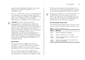
...the Web interface, do not need the following : 1 On a computer that has a Web browser Running the Discovery Application The 3Com Baseline Switch 2816-SFP/2824-SFP Plus CD-ROM contains, among others, the Discovery application. It also introduces the menu items and buttons that is connected ... following : ■ The Discovery application, which is included on 3Com Baseline Switch 2816-SFP/2824-SFP Plus CD-ROM that is supplied with your Switch ■ A computer that is connected to the Switch and that is assigned to the Switch, and configure its CD drive. To use to function as ...
...the Web interface, do not need the following : 1 On a computer that has a Web browser Running the Discovery Application The 3Com Baseline Switch 2816-SFP/2824-SFP Plus CD-ROM contains, among others, the Discovery application. It also introduces the menu items and buttons that is connected ... following : ■ The Discovery application, which is included on 3Com Baseline Switch 2816-SFP/2824-SFP Plus CD-ROM that is supplied with your Switch ■ A computer that is connected to the Switch and that is assigned to the Switch, and configure its CD drive. To use to function as ...
User Manual
Page 22
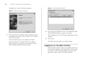
...need to enter the administration user name and password to gain access to the Switch, and then click Next. Discovery searches the network for 3Com devices. 22 CHAPTER 3: CONNECTING TO THE WEB INTERFACE The Welcome screen of... Discovery Figure 6 Discovered Devices Screen 2 If the computer has multiple network adapters, select the adapter that appears is complete, the Discovered Devices screen displays detected network devices. 3 On the Discovered Devices screen, click Baseline Switch 2816-SFP/2824...
...need to enter the administration user name and password to gain access to the Switch, and then click Next. Discovery searches the network for 3Com devices. 22 CHAPTER 3: CONNECTING TO THE WEB INTERFACE The Welcome screen of... Discovery Figure 6 Discovered Devices Screen 2 If the computer has multiple network adapters, select the adapter that appears is complete, the Discovered Devices screen displays detected network devices. 3 On the Discovered Devices screen, click Baseline Switch 2816-SFP/2824...
