Dell Vostro 400 Support Question
Dell Vostro 400 Support Question
Find answers below for this question about Dell Vostro 400.Need a Dell Vostro 400 manual? We have 2 online manuals for this item!
Question posted by shirinan on October 4th, 2013
How To Remove Power Supply Dell Vostro 400
The person who posted this question about this Dell product did not include a detailed explanation. Please use the "Request More Information" button to the right if more details would help you to answer this question.
Current Answers
Related Dell Vostro 400 Manual Pages
Owner's Manual - Page 7
... Cover 103
Inside View of Your Computer 105
System Board Components 106
Power Supply DC Connector Pin Assignments . . . . . 108
Memory 112 Memory Installation Guidelines 112 Installing Memory 113 Removing Memory 115
Cards 116 PCI and PCI Express Cards 116
Bezel 123 Removing the Bezel 123 Replacing the Bezel 125
Drives 126 Recommended Drive Cable...
Owner's Manual - Page 8
... Replacing the Battery 150
Power Supply 151 Replacing the Power Supply 152
I/O Panel 153 Removing the I/O Panel 154 Installing the I/O Panel 155
Processor Fan 155 Removing the Processor Fan/Heat Sink Assembly 156 Installing the Processor Fan/Heat Sink Assembly 157
Processor 158 Removing the Processor 158 Installing the Processor 159
Chassis Fan 162 Removing the Chassis Fan...
Owner's Manual - Page 18
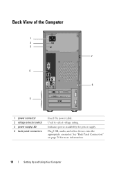
Back View of the Computer
1 2 3
7
4
6
5
1 power connector 2 voltage selector switch 3 power supply LED 4 back panel connectors
Insert the power cable. Plug USB, audio, and other devices into the appropriate connector. See "Back Panel Connectors" on page 20 for power supply.
Indicates power availability for more information.
18
Setting Up and Using Your Computer
Used to select voltage...
Owner's Manual - Page 85

... restart your boot device, ensure that has a bootable operating system or remove the floppy disk from drive A and restart the computer.
HARD DRIVE... K E R R O R - A chip on page 174. Replace the floppy disk with one that a bootable floppy disk is correct. Use external power source for assistance. DELL RECOMMENDS THAT YOU BACK UP YOUR DATA REGULARLY. U S B O V E R C U R R E N T E R R O R ...
Owner's Manual - Page 102
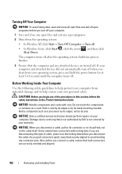
... you connect a cable, ensure that is not authorized by Dell is not covered by your operating system, press and hold the power button for at least 8-10 seconds until the computer turns ...
3 Ensure that the computer and any attached devices are correctly oriented and aligned.
102
Removing and Installing Parts If your computer and attached devices did not automatically turn off your computer....
Owner's Manual - Page 105
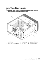
Inside View of Your Computer
CAUTION: Before you begin any of the procedures in this section, follow the safety instructions in the Product Information Guide.
1
2
3 4
6 5
1 optical drive
2 power supply 3 optional optical drive
4 floppy drive or Media Reader 5 hard drive
6 optional hard drive
Removing and Installing Parts
105
Owner's Manual - Page 108
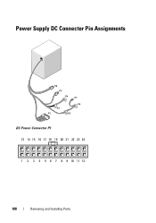
Power Supply DC Connector Pin Assignments
DC Power Connector P1 13 14 15 16 17 18 19 20 21 22 23 24
1 2 3 4 5 6 7 8 9 10 11 12
108
Removing and Installing Parts
Owner's Manual - Page 147

... Drive option.
13 Verify that your computer works correctly by running the Dell Diagnostics (see "Removing the Bezel" on page 123).
4 Align the tip of a Phillips...Remove the bezel (see "Dell Diagnostics" on the system board. Installing a Second Optical Drive 1 Follow the procedures in the optical drive bay.
7 Replace and tighten the two screws securing the optical drive.
8 Connect the power...
Owner's Manual - Page 151

...them on.
9 Enter system setup (see "Replacing the Computer Cover" on page 166).
Power Supply
CAUTION: Before you touch any of the old battery.
NOTICE: To prevent static damage to... on page 174) and restore the settings you recorded in the Product Information Guide. Removing and Installing Parts
151 2 1
1 battery release lever
2 battery (positive side)
7 Replace the computer cover...
Owner's Manual - Page 152
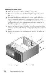
... "Before You Begin" on page 101.
2 Remove the computer cover (see "Removing the Computer Cover" on the side of the power supply.
5 Remove the four screws that attach the power supply to the back of the computer chassis.
1
2
1 power supply
2 screws (4)
152
Removing and Installing Parts You must route these cables properly when you remove them from being pinched or crimped...
Owner's Manual - Page 153
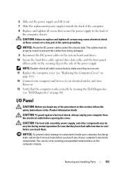
...). You can do so by running the Dell Diagnostics
(see "Replacing the Computer Cover" on
page 166). 12 Connect your computer's electronic components.
Removing and Installing Parts
153
Be sure that secure the power supply to the securing clip on the side of the power supply.
6 Slide out the power supply and lift it out. 7 Slide the replacement...
Owner's Manual - Page 155
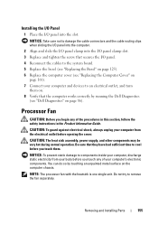
...Product Information Guide.
CAUTION: The heat sink assembly, power supply, and other components may be very hot during normal... the Bezel" on page 125). 6 Replace the computer cover (see "Dell Diagnostics" on the computer chassis. Installing the I/O Panel
1 Place the ... touching an unpainted metal surface on page 86). Removing and Installing Parts
155
Processor Fan
CAUTION: Before you...
Owner's Manual - Page 162
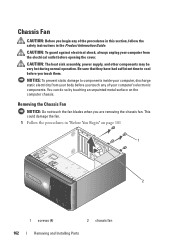
..." on the computer chassis. You can do so by touching an unpainted metal surface on page 101
1
2
1 screws (4)
2 chassis fan
162
Removing and Installing Parts CAUTION: The heat sink assembly, power supply, and other components may be very hot during normal operation. This could damage the fan. 1 Follow the procedures in the Product...
Owner's Manual - Page 164
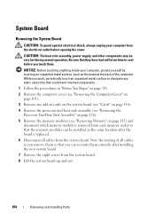
...power supply, and other components may be installed in cards on the system board (see "Cards" on page 116).
4 Remove the processor and heat sink assembly (see "Removing the Processor Fan/Heat Sink Assembly" on page 156).
5 Remove the memory modules (see "Removing... the memory modules can re-route them .
System Board
Removing the System Board
CAUTION: To guard against electrical shock, always ...
Owner's Manual - Page 169
...) NIC
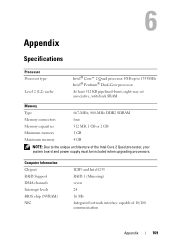
ICH9 and Intel G33 RAID 1 (Mirroring) seven 24 16 Mb Integrated network interface capable of the Intel Core 2 Quad processor, your system board and power supply must be included when upgrading processors. Appendix
Specifications
Processor Processor type
Level 2 (L2) cache
Intel® Core™ 2 Quad processor.
Owner's Manual - Page 172
...
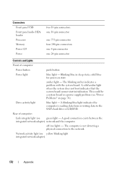
blue light - Blinking blue in sleep state;
off (no light) - Network activity light (on green light - This could be a system board or a power supply problem (see "Power Problems" on state
amber light - The computer is reading data from or writing data to the network. Drive activity light
blue light -
A blinking blue light ...
Owner's Manual - Page 173
... 500 Hz at 0.001 to 0.01 G2/Hz
40 G +/- 5% with pulse duration of 2 msec +/- 10% (equivalent to 20 in/sec [51 cm/sec])
Appendix
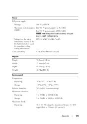
173 Power
DC power supply:
Wattage
300 W or 350 W
Maximum heat dissipation (MHD)
For 300 W power supply:162 W MHD
For 350 W power supply: 188W MHD NOTE: Heat dissipation is calculated by using the...
Owner's Manual - Page 186
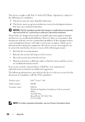
The following measures:
• Reorient the receiving antenna.
• Relocate the system with the FCC regulations:
Product name: Model number: Company name:
Dell™ Vostro™ 400
DCMF
Dell Inc. Operation is subject to the following two conditions:
1 This device may cause undesired operation.
If necessary, consult a representative of the FCC Rules. Worldwide Regulatory ...
Owner's Manual - Page 203

uninterruptible power supply - UPS systems typically provide surge suppression and may also provide voltage regulation. A hardware ...A UPS keeps a computer running for your computer. USB - Devices are displayed on your computer.
Video memory is no electrical power.
Character-based software, such as x horizontal pixels by y vertical pixels by y rows of a floppy disk. When an ...
Owner's Manual - Page 204
... a resistance of 1 ohm when a current of power for 1 hour or 33 W for 2 hours. watt-hour - You can supply 66 W of 1 ampere flows through the Windows ...controllers that cannot be installed or removed with each other over the air waves using cellular technology and covering a much larger geographic area than WLAN. turned on the Windows desktop. wallpaper - extended graphics array ...
Similar Questions

How Do I Install A Motherboard For A Vostro 400 Desktop?
(Posted by mmseTon 9 years ago)


How To Remove Power Supply From Dell Inspiron 660s
I can't find a way to take out the old power supply in my Inspiron 660s. It's loose but there I no r...
I can't find a way to take out the old power supply in my Inspiron 660s. It's loose but there I no r...
(Posted by sfishesfish 10 years ago)
