Dell PowerEdge T310 Support Question
Dell PowerEdge T310 Support Question
Find answers below for this question about Dell PowerEdge T310.Need a Dell PowerEdge T310 manual? We have 6 online manuals for this item!
Question posted by strikEj on April 12th, 2014
How To Upgrade T310 To Redundant Power
The person who posted this question about this Dell product did not include a detailed explanation. Please use the "Request More Information" button to the right if more details would help you to answer this question.
Current Answers
Related Dell PowerEdge T310 Manual Pages
Information
Update - Power Infrastructure Sizing - Page 1

... consumption for sizing the infrastructure. June 2009
Combined use of the power supply power rating. Example: If a server power supply is met for 10KW. Information Update:
Power Infrastructure Sizing
Properly sizing system power consumption benefits an efficient IT environment. By contrast, if the power supply rated value or 1000W were used for many hardware configurations and can...
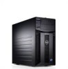
Getting Started Guide - Page 3
Dell™ PowerEdge™ T310 Systems
Getting Started With Your System
Regulatory Model E09S Regulatory Type E09S001
Getting Started Guide - Page 4
... of these materials in the United States and other countries;
Microsoft, Windows, Windows Server, and Hyper-V are registered trademarks of data if instructions are not followed. SUSE is...Other trademarks and trade names may be used in this text: Dell, the DELL logo, and PowerEdge are registered trademarks of Microsoft Corporation in this document to refer to hardware or loss of Red ...
Getting Started Guide - Page 11
...)
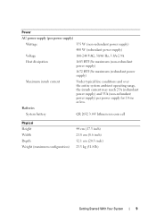
Maximum inrush current
Under typical line conditions and over the entire system ambient operating range, the inrush current may reach 25A (redundant power supply) and 35A (non-redundant power supply) per power supply for 10 ms or less. Batteries
System battery
CR 2032 3.0-V lithium ion coin cell
Physical Height Width Depth Weight (maximum configuration)
44...
Hardware Owner's Manual - Page 2
... trademarks and trade names may be used in this text: Dell, the DELL logo, and PowerEdge are trademarks of your computer. WARNING: A WARNING indicates a potential for property damage, personal ...injury, or death. All rights reserved. MS-DOS, Microsoft, Windows, and Windows Server are not followed.
Reproduction of these materials in any proprietary interest in this document to...
Hardware Owner's Manual - Page 6

... and Tape Drives 99 Removing an Optical or a Tape Drive 99 Installing an Optical or Tape Drive 100
Power Supplies 103 Removing a Redundant Power Supply 103 Installing a Redundant Power Supply 104 Removing a Non-Redundant Power Supply . . . 105 Installing a Non-Redundant Power Supply . . . . 106
System Fan 106 Removing the System Fan 106 Installing the System Fan 107
System Memory 108...
Hardware Owner's Manual - Page 20
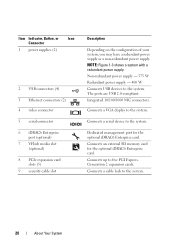
... media slot
(optional) 8 PCIe expansion card
slots (5) 9 security cable slot
Description
Depending on the configuration of your system, you may have a redundant power supply or a non-redundant power supply. Non-redundant power supply - 375 W Redundant power supply - 400 W Connects USB devices to the system.
20
About Your System
Connects a cable lock to the system. Integrated 10/100/1000...
Hardware Owner's Manual - Page 22

... matches the capacity of the other power supply. When hot-adding a power supply, this indicates that the power supply is mismatched with the other installed power supply. Figure 1-4. Replace the power supply that has the flashing indicator with the power supply.
• Alternating green and amber - Redundant Power Supply Status Indicator
1 1 power supply status indicator
22
About...
Hardware Owner's Manual - Page 23
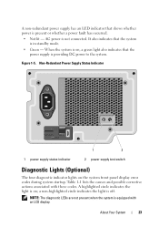
... in standby mode. • Green - Non-Redundant Power Supply Status Indicator
1
2
1 power supply status indicator
2 power supply test switch
Diagnostic Lights (Optional)
The four diagnostic indicator lights on ; A non-redundant power supply has an LED indicator that the
power supply is providing DC power to the system. When the system is on, a green light also indicates that shows...
Hardware Owner's Manual - Page 79
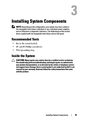
... system keylock • #1 and #2 Phillips screwdrivers • Wrist grounding strap
Inside the System
CAUTION: Many repairs may have cabled or hot-swappable hard drives, redundant or non-redundant power supplies, and an LCD panel or diagnostic indicators. Recommended Tools
• Key to servicing that came with hot-swappable hard drives and an LCD...
Hardware Owner's Manual - Page 103
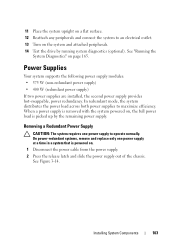
... system supports the following power supply modules: • 375 W (non-redundant power supply) • 400 W (redundant power supply) If two power supplies are installed, the second power supply provides hot-swappable, power redundancy. Removing a Redundant Power Supply
CAUTION: The system requires one power supply at a time in a system that is powered on , the full power load is removed with...
Hardware Owner's Manual - Page 104
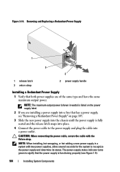
... power supply handle
Installing a Redundant Power Supply
1 Verify that both power supplies are installing a power supply into a bay that the power supply is fully seated and the release latch snaps into place.
4 Connect the power cable to the power supply and plug the cable into the chassis until the power supply is functioning properly (see "Removing a Redundant Power Supply" on the power...
Hardware Owner's Manual - Page 105
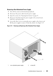
... on page 85. 4 Disconnect all attached peripherals. 2 Disconnect the power cable from the chassis. Removing and Replacing a Non-Redundant Power Supply
1
2
1 non-redundant power supply
2 screws (3)
Installing System Components
105 Figure 3-15. Removing a Non-Redundant Power Supply
1 Turn off the system and all cables from the power supply to the system board,
hard drives and optical drive...
Hardware Owner's Manual - Page 106
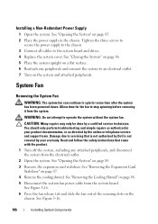
... attempt to an electrical outlet. 7 Turn on page 88. 5 Disconnect the system fan power cable from the electrical outlet. 2 Open the system. You should only perform troubleshooting and simple...of the securing slots on page 85. 3 Remove the expansion card stabilizer. Installing a Non-Redundant Power Supply
1 Open the system.
Damage due to stop spinning before removing it from the system...
Hardware Owner's Manual - Page 126
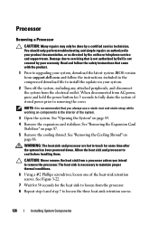
... step 6 and step 7 to touch for 3 seconds to fully drain the system of stored power prior to cool before handling them. NOTE: It is recommended that you intend to servicing that came with the product.
1 Prior to upgrading your system, download the latest system BIOS version from the electrical outlet. WARNING: The...
Hardware Owner's Manual - Page 140

... Reattach any attached peripherals, and disconnect the system from the electrical outlet and peripherals. 2 Remove the power supplies. See "Removing a Redundant Power Supply" on page 103 and "Removing a Non-Redundant Power Supply" on page 85. 4 Disconnect all the power cables connected to their original locations.
You should only perform troubleshooting and simple repairs as directed by...
Hardware Owner's Manual - Page 141

... up. 7 Pull the board away from the chassis until the securing slots on the
board are free from the tabs on the chassis.
Figure 3-29. Power Distribution Board
1 4
2
3
5
1 blue release pin 3 securing slots 5 power distribution board cables (5)
2 power-distribution board 4 redundant power supplies (2)
Installing System Components
141
Hardware Owner's Manual - Page 142
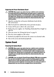
...in your warranty. Be sure to create a recovery key during program or system setup. Replacing the Power Distribution Board
CAUTION: Many repairs may only be done by a certified service technician. Read and follow ... the online or telephone service and support team.
See "Installing a Redundant Power Supply" on the chassis.
2 Slide the board down until the blue release pin locks into place. 3...
Hardware Owner's Manual - Page 184
...RAID 10, and RAID 50.
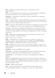
processor -
RAM -
ROM - Power distribution unit. A power source with software or hardware, that initiates your system.
A single ...attached storage devices to appear to a server to be revised to a system. ... A registered DDR3 memory module.
Remote access controller. Redundant array of code in ROM include the program that contains information supplementing...
Hardware Owner's Manual - Page 191

...
P
password disabling, 174
setup, 74 system, 72
phone numbers, 177
POST accessing system features, 11
power indicators, 12, 22
power supplies indicators, 22 removing, 103, 105 replacing, 104, 106 troubleshooting, 153
processor installing, 129 removing, 126 upgrades, 126
R
removing control panel assembly, 136 expansion cards, 118 hard drive (cabled), 95 hard drive blank...
Similar Questions

How To Install Dell Redundant Power Supply Poweredge 2900
(Posted by mikkaneva 9 years ago)

Why Does My Dell Poweredge T310 Have Two Power Cords
(Posted by pasj 10 years ago)

Memory Error When Upgrading Dell Poweredge T310 Server
(Posted by zsgmpablit 10 years ago)

Dell Server Poweredge T310 Can't Find The Raid Drive
(Posted by monSERM 10 years ago)

How To Swap Dell Poweredge 2950 Redundant Power Supply
(Posted by ewmore 10 years ago)