
Dell OptiPlex 755 Support Question
Dell OptiPlex 755 Support Question
Find answers below for this question about Dell OptiPlex 755.Need a Dell OptiPlex 755 manual? We have 3 online manuals for this item!
Question posted by rthrob on March 29th, 2014
How Do You Remove The Front Panel Of Optiplex 755 Sff
The person who posted this question about this Dell product did not include a detailed explanation. Please use the "Request More Information" button to the right if more details would help you to answer this question.
Current Answers
Related Dell OptiPlex 755 Manual Pages
Quick Reference
Guide - Page 6
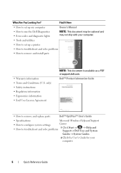
... install parts
• Warranty information • Terms and Conditions (U.S. Dell™ Product Information Guide
• How to remove and replace parts
Dell™ OptiPlex™ User's Guide
• Specifications
Microsoft Windows Help and Support
• How to configure system settings
Center
• How to troubleshoot and solve problems
1 Click ...
Quick Reference
Guide - Page 32
...device, to the connector on the graphics card. NOTE: If you touch it aside on the back panel, remove the padlock.
3 Locate the cover release latch shown in this connector will be covered by a cap....dual monitors, use the y-cable that a graphics card heat sink has had sufficient time to cool before removing the computer cover.
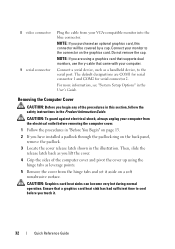
1 Follow the procedures in "Before You Begin" on page 13.
2 If ...
Quick Reference
Guide - Page 43
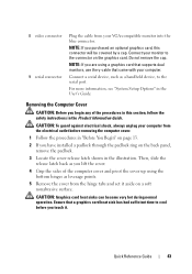
...the sides of the procedures in this connector will be covered by a cap. Do not remove the cap.
Connect your monitor to the serial port.
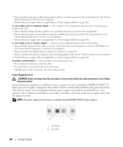
For more information, see "System Setup...VGA-compatible monitor into the blue connector. Removing the Computer Cover
CAUTION: Before you have installed a padlock through the padlock ring on the back panel, remove the padlock.
3 Locate the cover release...
Quick Reference
Guide - Page 51
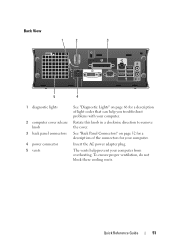
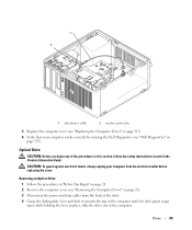
...View
1
2
3
5
4
1 diagnostic lights
2 computer cover release knob
3 back panel connectors
4 power connector 5 vents
See "Diagnostic Lights" on page 52 for your computer.
Insert the AC... Panel Connectors" on page 66 for a description of the connectors for a description of light codes that can help prevent your computer from overheating. Rotate this knob in a clockwise direction to remove the...
Quick Reference
Guide - Page 75
... files, and so on the computer. To see if System Restore is enabled: 1 Click Start→ Control Panel→ Performance and Maintenance→ System. 2 Click the System Restore tab and ensure that Turn off System Restore... state it was in certain countries or on the hard drive and removes any programs or drivers installed after you reinstall Windows XP with www.dell.com appears at ...
User's Guide - Page 5
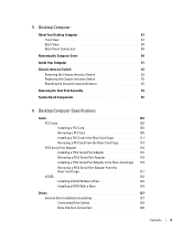
... 87 Back View 88 Back Panel Connectors 89
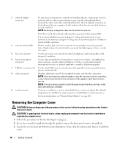
Removing the Computer Cover 90
Inside Your Computer 91
Chassis Intrusion Switch 92 Removing the Chassis Intrusion Switch 92 Replacing the Chassis Intrusion Switch 93 Resetting the Chassis Intrusion Detector 93
Removing the Heat Sink Assembly 94
System Board Components 95
6 Desktop Computer Specifications
Cards 103 PCI...
User's Guide - Page 18
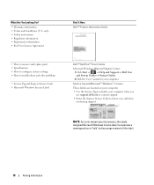
...Code • Microsoft Windows License Label
Find It Here Dell™ Product Information Guide
Dell™ OptiPlex™ User's Guide Microsoft Windows Help and Support Center
1 Click Start or → Help ... Ergonomics information • End User License Agreement
• How to remove and replace parts • Specifications • How to configure system settings • How to discourage...
User's Guide - Page 27
...a graphics card that supports dual monitors, use Category 5 wiring and connectors for serial connector 2. Removing the Computer Cover
CAUTION: Before you lift the
cover.
27
Mini Tower Computer 3 network adapter ... page 281.
For more information, see "System Setup Options" on the back panel of the network cable to the connector on its side as printers and keyboards.
8...
User's Guide - Page 45
...Begin" on page 21. 2 Remove the computer cover (see "System Setup" on the back panel of the computer.
15 If you will remain in connectors on the back panel of the computer. b Connect external... adapter: a Enter system setup, select Network Controller, and change the setting to Off (see "Removing the Computer Cover" on page 27). 3 Gently push the release tab on the card retention latch...
User's Guide - Page 46
... empty card-slot openings is necessary to the audio connectors on the back panel of the computer.
46
Cards The brackets keep dust and dirt out of...to On (see "Replacing the Computer Cover" on page 317), reconnect the computer and devices to the card.
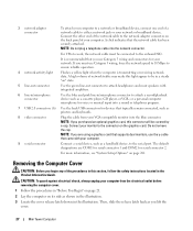
5 If you are removing the card permanently, install a filler bracket in the empty card-slot opening.
2
1
3
4 5
6
1 card retention latch...
User's Guide - Page 47
...release tab on page 280).
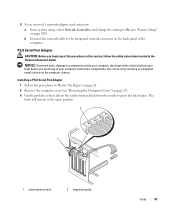
Installing a PS/2 Serial Port Adapter 1 Follow the procedures in "Before You Begin" on page 21. 2 Remove the computer cover (see "System Setup" on the card retention latch from the inside your computer, discharge static electricity from your computer's ...Information Guide. You can do so by touching an unpainted metal surface on the back panel of the computer.
User's Guide - Page 64
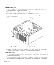
... shoulder screws from the existing drive and attach the screws to the replacement drive.
2 If you are installing a new floppy drive, remove the drive-panel insert for the 3.5-inch drive bay, remove the shoulder screws from the back of the floppy drive.
2
1
1 floppy drive
2 drive release latch
6 Grasp the sliding plate lever and...
User's Guide - Page 69
...sliding plate lever and slide it towards the top of the computer. Removing an Optical Drive 1 Follow the procedures in "Before You Begin" on page 21. 2 Remove the computer cover (see "Dell Diagnostics" on page 27). 3 ...in place, slide the drive out of the computer until the drive panel snaps open; CAUTION: To guard against electrical shock, always unplug your computer works correctly by running the...
User's Guide - Page 90
...in a steady "on the back panel, remove the padlock. 3 Locate the cover release latch shown in this connector will be covered by a cap. Do not remove the cap.
Connect your computer. ...this light appear to be connected to the onboard NIC.
NOTE: If you lift the
cover.
90
Desktop Computer
NOTE: Do not plug a telephone cable into a sound or telephony program.
7 USB 2.0 ...
User's Guide - Page 92
... not be present on page 90).
92
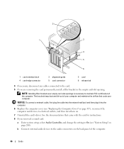
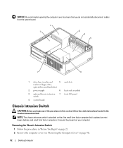
Desktop Computer Removing the Chassis Intrusion Switch
1 Follow the procedures... or floppy drive,
optical drive and hard drive)
2 power supply
6 heat sink assembly
3 optional chassis-intrusion 7 front I/O panel switch
4 system board
Chassis Intrusion Switch
CAUTION: Before you begin any of the procedures in this section, follow the safety instructions located...
User's Guide - Page 153

... procedures in this section, follow the safety instructions located in damage to the desktop computer. NOTICE: When sliding the I /O panel to the cable connectors and the cable routing clips. 6 Gently rotate and slide the I/O panel away from the computer. 7 Remove the cable from the electrical outlet before disconnecting them correctly when installing the new...
User's Guide - Page 307
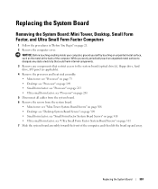
... Form Factor System Board Screws" on page 21. 2 Remove the computer cover. Replacing the System Board
Removing the System Board: Mini Tower, Desktop, Small Form Factor, and Ultra Small Form Factor Computers
... that could harm internal components. 3 Remove any components that restrict access to the system board (optical drive[s], floppy drive, hard drive, I/O panel (as the metal at the back ...
User's Guide - Page 340
... Supply Self-Test" on page 340). If your mini tower, desktop, or small form factor computer has been certified for your computer)...."System Board Components" section for your computer). • Remove and then reinstall all components and cables are properly installed ...located). • Ensure that the main power cable and front panel cable are securely connected to the system board (see the "...
User's Guide - Page 345
...• If the power light is required. Remove and then reinstall any cards (see "Memory" on the back of interference are securely connected to verify that the main power cable and front panel cable are : - Some possible causes of the... a computer problem.
Ensure that the computer turns on a power strip - On the desktop
computer, a solid green light indicates
a network connection.
User's Guide - Page 373
... away from the receiver.
• Plug the system into a different outlet so that may cause interference with the FCC regulations:
• Product name: Dell™ OptiPlex™ 755
• Model numbers: DCTR, DCNE, DCSM, DCCY
• Company name: Dell Inc.


