Dell OptiPlex 745 Support Question
Dell OptiPlex 745 Support Question
Find answers below for this question about Dell OptiPlex 745.Need a Dell OptiPlex 745 manual? We have 1 online manual for this item!
Question posted by rx14crazy on April 9th, 2014
How To Remove Fan From Optiplex 745
The person who posted this question about this Dell product did not include a detailed explanation. Please use the "Request More Information" button to the right if more details would help you to answer this question.
Current Answers
Related Dell OptiPlex 745 Manual Pages
Quick Reference
Guide - Page 2

... of Dell Inc. All rights reserved. Other trademarks and trade names may be used in this text: Dell, the DELL logo, Inspiron, Dell Precision, Dimension, OptiPlex, Latitude, PowerEdge, PowerVault, PowerApp, and Dell OpenManage are registered trademarks of Microsoft Corporation. NOTICE: A NOTICE indicates potential damage to change without the written permission of...
Quick Reference
Guide - Page 3
... Factor Computer - Back View 23 Ultra-Small Form Factor Computer - Front View 13 Desktop Computer - Back View 18 Small Form Factor Computer - Back-Panel Connectors 23
Removing the Computer Cover 24 Before You Begin 25 Mini Tower Computer 26 Desktop Computer 27 Small Form Factor Computer 28 Ultra-Small Form Factor Computer 30...
Quick Reference
Guide - Page 5
... • My computer documentation • My device documentation • Desktop System Software (DSS)
• How to remove and replace parts • Specifications • How to configure system ...diagnostic program for my computer • Drivers for technicians or experienced users. Dell™ OptiPlex™ User's Guide
Microsoft Windows XP Help and Support Center 1 Click Start→ ...
Quick Reference
Guide - Page 12
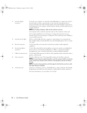
... USB connectors for serial connector 2. NOTE: If you use the y-cable that typically remain connected, such as a cassette player, CD player, or VCR.; Do not remove the cap. Connect your computer. A click indicates that you are COM1 for serial connector 1 and COM2 for devices that came with your network. A high volume...
Quick Reference
Guide - Page 16
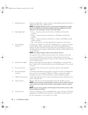
... between a 10-Mbps network and the computer.
• Orange - On computers with a network connector card, use Category 5 wiring and connectors for serial connector 2. Do not remove the cap. For more information, see your online User's Guide.
2 link integrity light
• Green - book.book Page 16 Wednesday, August 16, 2006 3:18 PM...
Quick Reference
Guide - Page 21
Do not remove the cap.
It is recommended that you are COM1 for serial connector 1 and COM2 for devices that came with your monitor to a USB device). book....
Quick Reference
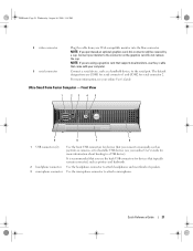
Guide - Page 23
...vents help you have a USB printer, plug it into a USB connector. Back-Panel Connectors
1
2
3
4
5
6
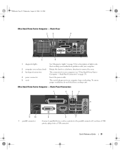
11 10 1 parallel connector
9
8
7
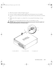
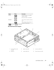
Connect a parallel device, such as a printer, to remove the cover. Insert the power cable. Back View
1
2
3
5
4
1 diagnostic lights
2 computer cover release knob 3 back-panel connectors
4 power connector 5 vents
See "Diagnostic Lights" on page...
Quick Reference
Guide - Page 24
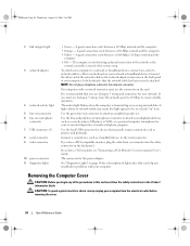
... a DVI-compatible monitor, plug the cable from the electrical outlet before removing the cover.
24
Quick Reference Guide If you must use Category 3 ...pink line-in this light appear to the serial connector. or a personal computer microphone for your network.
Removing the Computer Cover
CAUTION: Before you troubleshoot problems with a network connector card, use Category 5 wiring and...
Quick Reference
Guide - Page 25
... the computer.
1 Turn off your computer and all attached devices from the electrical outlet before removing the cover. Do not touch the components or contacts on your own personal safety. NOTICE: When... outlets, and then press the
power button to ground the system board. 4 If applicable, remove the computer stand (for instructions, see the documentation that is not authorized by Dell is not...
Quick Reference
Guide - Page 26
... Reference Guide book.book Page 26 Wednesday, August 16, 2006 3:18 PM
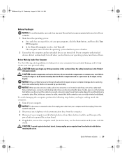
5 Remove the computer cover: • Remove the mini tower computer cover (see "Mini Tower Computer" on page 26). • Remove the desktop computer cover (see "Desktop Computer" on page 27). • Remove the small form factor computer cover (see "Small Form Factor Computer" on...
Quick Reference
Guide - Page 27
... book.book Page 27 Wednesday, August 16, 2006 3:18 PM
1 2 3
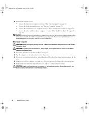
1 security cable slot
2 cover release latch
3 padlock ring
Desktop Computer
CAUTION: Before you have installed a padlock through the padlock ring on the back panel, remove the padlock.
CAUTION: To guard against electrical shock, always unplug your computer from the electrical outlet before...
Quick Reference
Guide - Page 28
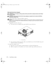
Ensure that a graphic card heatsink has had sufficient time to cool before removing the computer cover.
28
Quick Reference Guide CAUTION: To guard against electrical shock, always ...begin any of the computer cover and pivot the cover up using the hinge tabs as leverage points. 5 Remove the cover from the electrical outlet before you lift the cover.
4 Grip the sides of the procedures in...
Quick Reference
Guide - Page 29
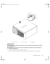
Then, slide the release latch back as leverage points.
5 Remove the cover from the hinge tabs and set it .
1
3
2
1 security cable slot
2 cover release latch
... of the computer cover and pivot the cover up using the bottom hinges as you touch it aside on the back panel, remove the padlock.
3 Locate the cover release latch shown in "Before You Begin" on page 25.
2 If you have installed...
Quick Reference
Guide - Page 30
... shown in the Product Information Guide. a If a security device is installed in the security cable slot, remove the device.
1
1 release button
b Press on page 25. CAUTION: To guard against electrical shock,...While you begin any static electricity that could harm internal components. 2 If applicable, remove the cable cover. b Slide the computer cover forward by touching an unpainted metal ...
Quick Reference
Guide - Page 37
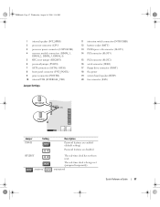
... PCI connector (SLOT3)
15 PCI connector (SLOT2) 16 serial connector (SER2) 17 floppy drive connector (DSKT) 18 flea power 19 system board speaker (BEEP) 20 fan connector (FAN)
Jumper PSWD
Setting
Description
Password features are disabled.
Quick Reference
Guide - Page 38

book.book Page 38 Wednesday, August 16, 2006 3:18 PM
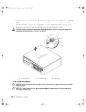
Small Form Factor Computer
3 2 1
4 5
1 drive-release latch
4 optional chassis-intrusion switch
7 heat sink and blower assembly
2 optical drive 5 hard drive
6 7
3 power supply and fan 6 system board
38
Quick Reference Guide
Quick Reference
Guide - Page 40
... module connectors (DIMM_1,
DIMM_2, DIMM_3, DIMM_4) 5 RTC reset jumper (RTCRST) 6 password jumper (PSWD) 7 SATA connectors (SATA0, SATA1) 8 front-panel connector (FNT_PANEL) 9 power connector (POWER) 10 fan connector (FAN2)
Jumper Settings
11 intrusion switch connector (INTRUDER) 12 internal USB connector (USB) 13 battery socket (BATT) 14 PCI Express x16 connector (SLOT1)
15...
Quick Reference
Guide - Page 41
unjumpered
Ultra-Small Form Factor Computer
1 2
3
6 5
1 fan shroud/ heat sink assembly
4 hard drive
2 speaker (optional) 5 security cable slot
4
3 memory modules (2) 6 chassis intrusion switch
Quick Reference Guide
41
RTCRST jumpered
The real-time ...
Quick Reference
Guide - Page 42
book.book Page 42 Wednesday, August 16, 2006 3:18 PM
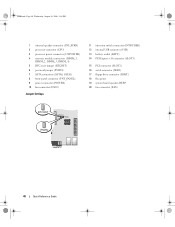
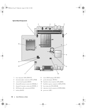
System Board Components
1
2
3
4
5 6
14
7
8
13
12
9
11
10
1 fan connector (FAN_FRONT) 2 internal speaker connector (INT_SPKR) 3 system board speaker (BEEP) 4 channel B memory connector (DIMM_2) 5 channel A memory connector (DIMM_1) 6 SATA data cable connector(SATA0) 7 battery (BATT)
8 ...
Quick Reference
Guide - Page 58
... Wednesday, August 16, 2006 3:18 PM
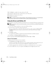
18 Click Finish to complete the setup, and remove the CD. 19 Reinstall the appropriate drivers with the Drivers and Utilities CD. 20 Reinstall ... on the screen. 2 Click the appropriate driver and follow the instructions to download the driver to the Windows desktop. 2 Insert the Drivers and Utilities CD into the CD drive. NOTE: To access device drivers and user ...
Similar Questions

How I Remove Dell Optiplex 745 Core 2 Duo Rear Fan Failure Error
(Posted by TGerCha 9 years ago)

How To Remove Fan Cover From Optiplex 745 Minitower
(Posted by CJtmpuse 10 years ago)


