
User Guide
Page 3
... use e-mail instead. It contains information on their network. E-mail: techwriters@zyxel.com.tw ES-1124 User's Guide 3 Thank you! Related Documentation • Quick Start Guide The Quick Start Guide is intended for people who want to install the switch on installing your switch. • Supporting Disk Refer to the included CD for support documents...
... use e-mail instead. It contains information on their network. E-mail: techwriters@zyxel.com.tw ES-1124 User's Guide 3 Thank you! Related Documentation • Quick Start Guide The Quick Start Guide is intended for people who want to install the switch on installing your switch. • Supporting Disk Refer to the included CD for support documents...
User Guide
Page 4
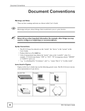
Syntax Conventions • The ES-1124 may be referred to as the "switch", the "device" or the "system" in this User's Guide. • Product labels are shown in this User's Guide may use the following generic icons. For ..." or "1048576" and so on. • "e.g.," is a shorthand for "for example, other words". The ES-1124 icon is not an exact representation of measurement may denote the "metric" value or the "scientific" value. the ES-1124 Computer Server Printer Switch Internetl 4 ES-1124 User's Guide Icons Used in Figures Figures in bold font. • Units of your...
Syntax Conventions • The ES-1124 may be referred to as the "switch", the "device" or the "system" in this User's Guide. • Product labels are shown in this User's Guide may use the following generic icons. For ..." or "1048576" and so on. • "e.g.," is a shorthand for "for example, other words". The ES-1124 icon is not an exact representation of measurement may denote the "metric" value or the "scientific" value. the ES-1124 Computer Server Printer Switch Internetl 4 ES-1124 User's Guide Icons Used in Figures Figures in bold font. • Units of your...
User Guide
Page 7
...Installation and Troubleshooting ...... 13 Chapter 1 Getting to Know Your Switch 15 1.1 Introduction ...15 1.1.1 Backbone Application 15 1.1.2 Bridging Example ...15 Chapter 2 Hardware Installation ...Switch on a Rack 18 2.2.1 Rack-mounted Installation Requirements 18 2.2.2 Attaching the Mounting Brackets to the Switch 18 2.2.3 Mounting the Switch on a Rack 19 Chapter 3 Hardware Overview...21 3.1 Panel Connections ...21 3.1.1 Ethernet Ports ...21 3.1.2 Dual Personality GbE Interfaces 22 3.1.3 Mini-GBIC Slots ...22 3.2 Rear Panel ...24 3.2.1 Power Connector ...24 3.3 LEDs ...24 ES-1124...
...Installation and Troubleshooting ...... 13 Chapter 1 Getting to Know Your Switch 15 1.1 Introduction ...15 1.1.1 Backbone Application 15 1.1.2 Bridging Example ...15 Chapter 2 Hardware Installation ...Switch on a Rack 18 2.2.1 Rack-mounted Installation Requirements 18 2.2.2 Attaching the Mounting Brackets to the Switch 18 2.2.3 Mounting the Switch on a Rack 19 Chapter 3 Hardware Overview...21 3.1 Panel Connections ...21 3.1.1 Ethernet Ports ...21 3.1.2 Dual Personality GbE Interfaces 22 3.1.3 Mini-GBIC Slots ...22 3.2 Rear Panel ...24 3.2.1 Power Connector ...24 3.3 LEDs ...24 ES-1124...
User Guide
Page 9
... List of Figures Figure 1 Backbone Application ...15 Figure 2 Bridging Application ...16 Figure 3 Attaching Rubber Feet ...17 Figure 4 Attaching the Mounting Brackets 18 Figure 5 Mounting the Switch on a Rack 19 Figure 6 Front Panel ...21 Figure 7 Transceiver Installation Example 23 Figure 8 Installed Transceiver ...23 Figure 9 Opening the Transceiver's Latch Example 23 Figure 10... Rear Panel ...24 Figure 12 Network Number and Host ID 32 Figure 13 Subnetting Example: Before Subnetting 34 Figure 14 Subnetting Example: After Subnetting 35 ES-1124 User's Guide 9
... List of Figures Figure 1 Backbone Application ...15 Figure 2 Bridging Application ...16 Figure 3 Attaching Rubber Feet ...17 Figure 4 Attaching the Mounting Brackets 18 Figure 5 Mounting the Switch on a Rack 19 Figure 6 Front Panel ...21 Figure 7 Transceiver Installation Example 23 Figure 8 Installed Transceiver ...23 Figure 9 Opening the Transceiver's Latch Example 23 Figure 10... Rear Panel ...24 Figure 12 Network Number and Host ID 32 Figure 13 Subnetting Example: Before Subnetting 34 Figure 14 Subnetting Example: After Subnetting 35 ES-1124 User's Guide 9

User Guide
Page 13
PART I Introduction, Hardware Installation and Troubleshooting This part contains the following: Getting to Know Your Switch (15) Hardware Installation and Connection (17) Hardware Overview (21) Troubleshooting (25) 13
PART I Introduction, Hardware Installation and Troubleshooting This part contains the following: Getting to Know Your Switch (15) Hardware Installation and Connection (17) Hardware Overview (21) Troubleshooting (25) 13
User Guide
Page 15
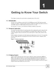
...29 for a full list of features available on the switch. 1.1.1 Backbone Application The switch is an ideal solution for a group of the switch. 1.1 Introduction The ES-1124 is an Ethernet switch with one port active at a time. The switch can be used standalone for small networks where rapid growth ...can connect to the switch. Figure 1 Backbone Application 1.1.2 Bridging Example In this ...
...29 for a full list of features available on the switch. 1.1.1 Backbone Application The switch is an ideal solution for a group of the switch. 1.1 Introduction The ES-1124 is an Ethernet switch with one port active at a time. The switch can be used standalone for small networks where rapid growth ...can connect to the switch. Figure 1 Backbone Application 1.1.2 Bridging Example In this ...
User Guide
Page 16
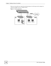
Figure 2 Bridging Application 16 ES-1124 User's Guide Chapter 1 Getting to Know Your Switch Moreover, the switch eases supervision and maintenance by allowing network managers to centralize multiple servers at a single location.
Figure 2 Bridging Application 16 ES-1124 User's Guide Chapter 1 Getting to Know Your Switch Moreover, the switch eases supervision and maintenance by allowing network managers to centralize multiple servers at a single location.
User Guide
Page 17
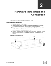
... between devices when stacking. Figure 3 Attaching Rubber Feet ES-1124 User's Guide 17 CHAPTER 2 Hardware Installation and Connection This chapter shows you how to install and connect the switch. 2.1 Freestanding Installation 1 Make sure the switch is enough clearance around the switch to support the weight of the switch and the connected cables. Make sure there is...
... between devices when stacking. Figure 3 Attaching Rubber Feet ES-1124 User's Guide 17 CHAPTER 2 Hardware Installation and Connection This chapter shows you how to install and connect the switch. 2.1 Freestanding Installation 1 Make sure the switch is enough clearance around the switch to support the weight of the switch and the connected cables. Make sure there is...
User Guide
Page 18
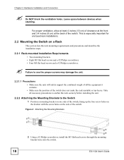
... the rack will safely support the combined weight of all the equipment it contains. • Make sure the position of the switch, lining up the four screw holes on the bracket with the screw holes on a Rack This section lists the rack mounting ... especially important for enclosed rack installations. 2.2 Mounting the Switch on the side of the switch. Figure 4 Attaching the Mounting Brackets 2 Using a #2 Philips screwdriver, install the M3 flat head screws through the mounting bracket holes into the switch. 18 ES-1124 User's Guide Leave space between devices when stacking.
... the rack will safely support the combined weight of all the equipment it contains. • Make sure the position of the switch, lining up the four screw holes on the bracket with the screw holes on a Rack This section lists the rack mounting ... especially important for enclosed rack installations. 2.2 Mounting the Switch on the side of the switch. Figure 4 Attaching the Mounting Brackets 2 Using a #2 Philips screwdriver, install the M3 flat head screws through the mounting bracket holes into the switch. 18 ES-1124 User's Guide Leave space between devices when stacking.
User Guide
Page 19
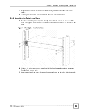
ES-1124 User's Guide 19 Proceed to the next section. 2.2.3 Mounting the Switch on a Rack 1 Position a mounting bracket (that is already attached to attach the second mounting bracket on the other side of the switch. 4 You may now mount the switch on a rack. Figure 5 Mounting the Switch on a Rack 2 Using a #2 Philips screwdriver,... install the M5 flat head screws through the mounting bracket holes into the rack. 3 Repeat steps 1 and 2 to the switch) on one side of the rack, lining up the two screw holes on the bracket with the screw holes on the side of the rack....
ES-1124 User's Guide 19 Proceed to the next section. 2.2.3 Mounting the Switch on a Rack 1 Position a mounting bracket (that is already attached to attach the second mounting bracket on the other side of the switch. 4 You may now mount the switch on a rack. Figure 5 Mounting the Switch on a Rack 2 Using a #2 Philips screwdriver,... install the M5 flat head screws through the mounting bracket holes into the rack. 3 Repeat steps 1 and 2 to the switch) on one side of the rack, lining up the two screw holes on the bracket with the screw holes on the side of the rack....
User Guide
Page 21
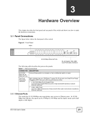
...in these ports to a computer, a hub, an Ethernet switch or router. In 10/100 Mbps Fast Ethernet, the speed can be 10 Mbps or 100 Mbps and the duplex mode can be half duplex or full duplex. ES-1124 User's Guide 21 Figure 6 Front Panel LEDs 10/100 Mbps.... 3.1 Panel Connections The figure below shows the front panel of the switch. CHAPTER 3 Hardware Overview This chapter describes the front panel and rear panel of the switch and shows you how to backbone Ethernet switches. 3.1.1 Ethernet Ports The switch has 24 10/100Mbps auto-negotiating, auto-crossover Ethernet ports.
...in these ports to a computer, a hub, an Ethernet switch or router. In 10/100 Mbps Fast Ethernet, the speed can be 10 Mbps or 100 Mbps and the duplex mode can be half duplex or full duplex. ES-1124 User's Guide 21 Figure 6 Front Panel LEDs 10/100 Mbps.... 3.1 Panel Connections The figure below shows the front panel of the switch. CHAPTER 3 Hardware Overview This chapter describes the front panel and rear panel of the switch and shows you how to backbone Ethernet switches. 3.1.1 Ethernet Ports The switch has 24 10/100Mbps auto-negotiating, auto-crossover Ethernet ports.
User Guide
Page 22
... mode can use transceivers that comply with the exposed section of PCB board facing down. 22 ES-1124 User's Guide A transceiver is operating. There are slots for details. The switch does not come with a straight-through or crossover Ethernet cable. 3.1.1.1 Default Ethernet Settings The... Gigabit port are connected at the same time, the Gigabit port will be disabled. You must use different transceivers to connect to Ethernet switches with different types of fiber-optic connectors. • Type: SFP connection interface • Connection speed: 1 Gigabit per second (Gbps)...
... mode can use transceivers that comply with the exposed section of PCB board facing down. 22 ES-1124 User's Guide A transceiver is operating. There are slots for details. The switch does not come with a straight-through or crossover Ethernet cable. 3.1.1.1 Default Ethernet Settings The... Gigabit port are connected at the same time, the Gigabit port will be disabled. You must use different transceivers to connect to Ethernet switches with different types of fiber-optic connectors. • Type: SFP connection interface • Connection speed: 1 Gigabit per second (Gbps)...
User Guide
Page 23
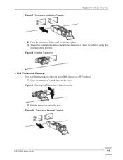
Figure 7 Transceiver Installation Example Chapter 3 Hardware Overview 2 Press the transceiver firmly until it is functioning properly. Figure 9 Opening the Transceiver's Latch Example 2 Pull the transceiver out of the slot. Check the LEDs to remove a mini GBIC transceiver (SFP module). 1 Open the transceiver's latch (latch styles vary). Figure 10 Transceiver Removal Example ES-1124 User's Guide 23 Figure 8 Installed Transceiver 3.1.3.2 Transceiver Removal Use the following steps to verify that it clicks into place. 3 The switch automatically detects the installed transceiver.
Figure 7 Transceiver Installation Example Chapter 3 Hardware Overview 2 Press the transceiver firmly until it is functioning properly. Figure 9 Opening the Transceiver's Latch Example 2 Pull the transceiver out of the slot. Check the LEDs to remove a mini GBIC transceiver (SFP module). 1 Open the transceiver's latch (latch styles vary). Figure 10 Transceiver Removal Example ES-1124 User's Guide 23 Figure 8 Installed Transceiver 3.1.3.2 Transceiver Removal Use the following steps to verify that it clicks into place. 3 The switch automatically detects the installed transceiver.
User Guide
Page 24
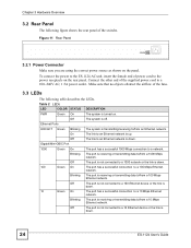
Connect the other end of the switche. Figure 11 Rear Panel 3.2.1 Power Connector Make sure you are using the correct power source as shown on the rear panel. On The link to an Ethernet network is off. To connect the power to the ES-1124 AC unit, insert the female end of ...the airflow of the fans. 3.3 LEDs The following figure shows the rear panel of the supplied power cord to an Ethernet network is down . 24 ES-1124 User's Guide Gigabit/Mini-GBIC Port 1000 Green On The port has a successful 1000 Mbps connection to /from a 100 Mbps Ethernet network. Off ...
Connect the other end of the switche. Figure 11 Rear Panel 3.2.1 Power Connector Make sure you are using the correct power source as shown on the rear panel. On The link to an Ethernet network is off. To connect the power to the ES-1124 AC unit, insert the female end of ...the airflow of the fans. 3.3 LEDs The following figure shows the rear panel of the supplied power cord to an Ethernet network is down . 24 ES-1124 User's Guide Gigabit/Mini-GBIC Port 1000 Green On The port has a successful 1000 Mbps connection to /from a 100 Mbps Ethernet network. Off ...
User Guide
Page 25
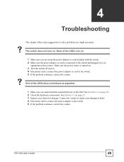
CHAPTER 4 Troubleshooting This chapter offers some suggestions to the switch. 5 If the problem continues, contact the vendor. ES-1124 User's Guide 25 Make sure the power source is connected to the switch and plugged in to the switch. 5 If the problem continues, contact the vendor. Contact the vendor to...See Section 3.1 on . 4 Disconnect and re-connect the power adaptor or cord to an appropriate power source. None of the LED. V The switch does not turn on. 1 Make sure you understand the normal behavior of the LEDs turn on page 24. 2 Check the hardware connections. See...
CHAPTER 4 Troubleshooting This chapter offers some suggestions to the switch. 5 If the problem continues, contact the vendor. ES-1124 User's Guide 25 Make sure the power source is connected to the switch and plugged in to the switch. 5 If the problem continues, contact the vendor. Contact the vendor to...See Section 3.1 on . 4 Disconnect and re-connect the power adaptor or cord to an appropriate power source. None of the LED. V The switch does not turn on. 1 Make sure you understand the normal behavior of the LEDs turn on page 24. 2 Check the hardware connections. See...
User Guide
Page 29
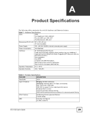
...~ 45º C Operation Humidity 10% ~ 90% RH Table 4 Firmware Specifications FEATURE DESCRIPTION Data Buffer 320 K Layer 2 Features Bridging: 8K MAC addresses Switching: Switching fabric: 8.8 Gbps, non-blocking Max. Table 3 LEDs Hardware Specifications PWR Per Gigabit port: 1000, LNK/ACT Per mini-GBIC port: LNK, ACT Per Ethernet...Other Features No-Blocking full wire speed architecture Fanless design EMC FCC Part 15 (Class A) CE EMC (Class A) ES-1124 User's Guide 29 APPENDIX A Product Specifications The following tables summarize the switch's hardware and firmware features.
...~ 45º C Operation Humidity 10% ~ 90% RH Table 4 Firmware Specifications FEATURE DESCRIPTION Data Buffer 320 K Layer 2 Features Bridging: 8K MAC addresses Switching: Switching fabric: 8.8 Gbps, non-blocking Max. Table 3 LEDs Hardware Specifications PWR Per Gigabit port: 1000, LNK/ACT Per mini-GBIC port: LNK, ACT Per Ethernet...Other Features No-Blocking full wire speed architecture Fanless design EMC FCC Part 15 (Class A) CE EMC (Class A) ES-1124 User's Guide 29 APPENDIX A Product Specifications The following tables summarize the switch's hardware and firmware features.
User Guide
Page 38
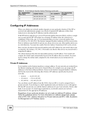
...(/31) 32768 NO. If the ISP or your network administrator assigns you with the Internet addresses for the appropriate IP addresses. Your switch will assign you should consult your networks are instructed to 192.168.255.0. You don't need to RFC 1597, Address Allocation for Private... on the network number, pick an IP address for your switch that is easy to the hosts without problems. However, the Internet Assigned Numbers Authority (IANA) has reserved the following three blocks of IP Address Space. 38 ES-1124 User's Guide The Internet Assigned Number Authority (IANA) reserved...
...(/31) 32768 NO. If the ISP or your network administrator assigns you with the Internet addresses for the appropriate IP addresses. Your switch will assign you should consult your networks are instructed to 192.168.255.0. You don't need to RFC 1597, Address Allocation for Private... on the network number, pick an IP address for your switch that is easy to the hosts without problems. However, the Internet Assigned Numbers Authority (IANA) has reserved the following three blocks of IP Address Space. 38 ES-1124 User's Guide The Internet Assigned Number Authority (IANA) reserved...
User Guide
Page 40
...will , at his own expense. ZyXEL Limited Warranty ZyXEL warrants to the original end user (purchaser) that product's page. 3 Select the certification you wish to view from any defects in a commercial environment. These limits are designed to proper operating 40 ES-1124 User's Guide This Class A ... the equipment. Appendix C Legal Information FCC Warning This device has been tested and found to comply with the limits for a Class A digital switch, pursuant to radio communications. CLASS 1 LASER PRODUCT APPAREIL A LASER DE CLASS 1 PRODUCT COMPLIES WITH 21 CFR 1040.10 AND 1040.11....
...will , at his own expense. ZyXEL Limited Warranty ZyXEL warrants to the original end user (purchaser) that product's page. 3 Select the certification you wish to view from any defects in a commercial environment. These limits are designed to proper operating 40 ES-1124 User's Guide This Class A ... the equipment. Appendix C Legal Information FCC Warning This device has been tested and found to comply with the limits for a Class A digital switch, pursuant to radio communications. CLASS 1 LASER PRODUCT APPAREIL A LASER DE CLASS 1 PRODUCT COMPLIES WITH 21 CFR 1040.10 AND 1040.11....