
User Guide
Page 3
...; Supporting Disk Refer to the included CD for support documents. • ZyXEL Web Site Please refer to www.zyxel.com for people who want to install the switch on their network. The Technical Writing Team, ZyXEL Communications Corp., 6 Innovation Road II, Science-Based Industrial Park, Hsinchu, 300, Taiwan. User Guide Feedback Help us help... improvement to the following address, or use e-mail instead. You should have at least a basic knowledge of TCP/IP networking concepts and topology. E-mail: techwriters@zyxel.com.tw ES-1124 User's Guide 3 Thank you!
...; Supporting Disk Refer to the included CD for support documents. • ZyXEL Web Site Please refer to www.zyxel.com for people who want to install the switch on their network. The Technical Writing Team, ZyXEL Communications Corp., 6 Innovation Road II, Science-Based Industrial Park, Hsinchu, 300, Taiwan. User Guide Feedback Help us help... improvement to the following address, or use e-mail instead. You should have at least a basic knowledge of TCP/IP networking concepts and topology. E-mail: techwriters@zyxel.com.tw ES-1124 User's Guide 3 Thank you!
User Guide
Page 4
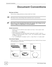
... about things that is" or "in other important information (for instance", and "i.e.," means "that could harm you or your device. the ES-1124 Computer Server Printer Switch Internetl 4 ES-1124 User's Guide The ES-1124 icon is not an exact representation of measurement may use the following generic icons. Document Conventions Document Conventions Warnings and Notes These...
... about things that is" or "in other important information (for instance", and "i.e.," means "that could harm you or your device. the ES-1124 Computer Server Printer Switch Internetl 4 ES-1124 User's Guide The ES-1124 icon is not an exact representation of measurement may use the following generic icons. Document Conventions Document Conventions Warnings and Notes These...
User Guide
Page 7
...Installation and Troubleshooting ...... 13 Chapter 1 Getting to Know Your Switch 15 1.1 Introduction ...15 1.1.1 Backbone Application 15 1.1.2 Bridging Example ...15 Chapter 2 Hardware Installation ...Switch on a Rack 18 2.2.1 Rack-mounted Installation Requirements 18 2.2.2 Attaching the Mounting Brackets to the Switch 18 2.2.3 Mounting the Switch on a Rack 19 Chapter 3 Hardware Overview...21 3.1 Panel Connections ...21 3.1.1 Ethernet Ports ...21 3.1.2 Dual Personality GbE Interfaces 22 3.1.3 Mini-GBIC Slots ...22 3.2 Rear Panel ...24 3.2.1 Power Connector ...24 3.3 LEDs ...24 ES-1124...
...Installation and Troubleshooting ...... 13 Chapter 1 Getting to Know Your Switch 15 1.1 Introduction ...15 1.1.1 Backbone Application 15 1.1.2 Bridging Example ...15 Chapter 2 Hardware Installation ...Switch on a Rack 18 2.2.1 Rack-mounted Installation Requirements 18 2.2.2 Attaching the Mounting Brackets to the Switch 18 2.2.3 Mounting the Switch on a Rack 19 Chapter 3 Hardware Overview...21 3.1 Panel Connections ...21 3.1.1 Ethernet Ports ...21 3.1.2 Dual Personality GbE Interfaces 22 3.1.3 Mini-GBIC Slots ...22 3.2 Rear Panel ...24 3.2.1 Power Connector ...24 3.3 LEDs ...24 ES-1124...
User Guide
Page 9
... List of Figures Figure 1 Backbone Application ...15 Figure 2 Bridging Application ...16 Figure 3 Attaching Rubber Feet ...17 Figure 4 Attaching the Mounting Brackets 18 Figure 5 Mounting the Switch on a Rack 19 Figure 6 Front Panel ...21 Figure 7 Transceiver Installation Example 23 Figure 8 Installed Transceiver ...23 Figure 9 Opening the Transceiver's Latch Example 23 Figure 10... Rear Panel ...24 Figure 12 Network Number and Host ID 32 Figure 13 Subnetting Example: Before Subnetting 34 Figure 14 Subnetting Example: After Subnetting 35 ES-1124 User's Guide 9
... List of Figures Figure 1 Backbone Application ...15 Figure 2 Bridging Application ...16 Figure 3 Attaching Rubber Feet ...17 Figure 4 Attaching the Mounting Brackets 18 Figure 5 Mounting the Switch on a Rack 19 Figure 6 Front Panel ...21 Figure 7 Transceiver Installation Example 23 Figure 8 Installed Transceiver ...23 Figure 9 Opening the Transceiver's Latch Example 23 Figure 10... Rear Panel ...24 Figure 12 Network Number and Host ID 32 Figure 13 Subnetting Example: Before Subnetting 34 Figure 14 Subnetting Example: After Subnetting 35 ES-1124 User's Guide 9

User Guide
Page 13
PART I Introduction, Hardware Installation and Troubleshooting This part contains the following: Getting to Know Your Switch (15) Hardware Installation and Connection (17) Hardware Overview (21) Troubleshooting (25) 13
PART I Introduction, Hardware Installation and Troubleshooting This part contains the following: Getting to Know Your Switch (15) Hardware Installation and Connection (17) Hardware Overview (21) Troubleshooting (25) 13
User Guide
Page 15
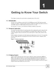
...time. It can connect computers and servers directly to the switch's port or connect other switches to the switch. CHAPTER 1 Getting to Know Your Switch This chapter introduces the main features and applications of the switch. 1.1 Introduction The ES-1124 is an ideal solution for small networks where rapid growth... 1 Backbone Application 1.1.2 Bridging Example In this example, all computers can share high-speed applications on the switch. ES-1124 User's Guide 15 The switch can connect to the corporate backbone. All users that need high bandwidth can be expected in the near ...
...time. It can connect computers and servers directly to the switch's port or connect other switches to the switch. CHAPTER 1 Getting to Know Your Switch This chapter introduces the main features and applications of the switch. 1.1 Introduction The ES-1124 is an ideal solution for small networks where rapid growth... 1 Backbone Application 1.1.2 Bridging Example In this example, all computers can share high-speed applications on the switch. ES-1124 User's Guide 15 The switch can connect to the corporate backbone. All users that need high bandwidth can be expected in the near ...
User Guide
Page 16
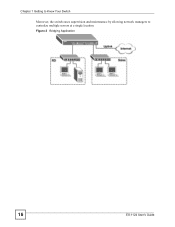
Figure 2 Bridging Application 16 ES-1124 User's Guide Chapter 1 Getting to Know Your Switch Moreover, the switch eases supervision and maintenance by allowing network managers to centralize multiple servers at a single location.
Figure 2 Bridging Application 16 ES-1124 User's Guide Chapter 1 Getting to Know Your Switch Moreover, the switch eases supervision and maintenance by allowing network managers to centralize multiple servers at a single location.
User Guide
Page 17
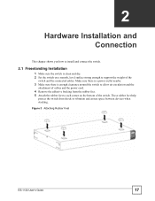
... Rubber Feet ES-1124 User's Guide 17 These rubber feet help protect the switch from the rubber feet. 5 Attach the rubber feet to each corner on a smooth, level surface strong enough to install and connect the switch. 2.1 Freestanding Installation 1 Make sure the switch is enough clearance around the switch to allow air...between devices when stacking. Make sure there is a power outlet nearby. 3 Make sure there is clean and dry. 2 Set the switch on the bottom of the switch. CHAPTER 2 Hardware Installation and Connection This chapter shows you how to support the weight of the...
... Rubber Feet ES-1124 User's Guide 17 These rubber feet help protect the switch from the rubber feet. 5 Attach the rubber feet to each corner on a smooth, level surface strong enough to install and connect the switch. 2.1 Freestanding Installation 1 Make sure the switch is enough clearance around the switch to allow air...between devices when stacking. Make sure there is a power outlet nearby. 3 Make sure there is clean and dry. 2 Set the switch on the bottom of the switch. CHAPTER 2 Hardware Installation and Connection This chapter shows you how to support the weight of the...
User Guide
Page 18
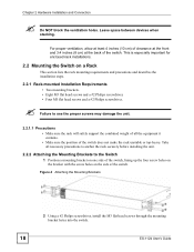
... the rack will safely support the combined weight of all the equipment it contains. • Make sure the position of the switch, lining up the four screw holes on the bracket with the screw holes on a Rack This section lists the rack mounting ...especially important for enclosed rack installations. 2.2 Mounting the Switch on the side of the switch. Figure 4 Attaching the Mounting Brackets 2 Using a #2 Philips screwdriver, install the M3 flat head screws through the mounting bracket holes into the switch. 18 ES-1124 User's Guide Chapter 2 Hardware Installation and Connection ...
... the rack will safely support the combined weight of all the equipment it contains. • Make sure the position of the switch, lining up the four screw holes on the bracket with the screw holes on a Rack This section lists the rack mounting ...especially important for enclosed rack installations. 2.2 Mounting the Switch on the side of the switch. Figure 4 Attaching the Mounting Brackets 2 Using a #2 Philips screwdriver, install the M3 flat head screws through the mounting bracket holes into the switch. 18 ES-1124 User's Guide Chapter 2 Hardware Installation and Connection ...
User Guide
Page 19
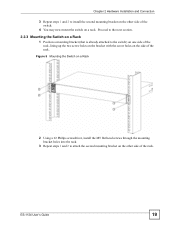
...and Connection 3 Repeat steps 1 and 2 to install the second mounting bracket on the other side of the switch. 4 You may now mount the switch on the side of the rack. Figure 5 Mounting the Switch on a Rack 2 Using a #2 Philips screwdriver, install the M5 flat head screws through the mounting bracket ...side of the rack, lining up the two screw holes on the bracket with the screw holes on a rack. ES-1124 User's Guide 19 Proceed to the next section. 2.2.3 Mounting the Switch on a Rack 1 Position a mounting bracket (that is already attached to attach the second mounting bracket on the ...
...and Connection 3 Repeat steps 1 and 2 to install the second mounting bracket on the other side of the switch. 4 You may now mount the switch on the side of the rack. Figure 5 Mounting the Switch on a Rack 2 Using a #2 Philips screwdriver, install the M5 flat head screws through the mounting bracket ...side of the rack, lining up the two screw holes on the bracket with the screw holes on a rack. ES-1124 User's Guide 19 Proceed to the next section. 2.2.3 Mounting the Switch on a Rack 1 Position a mounting bracket (that is already attached to attach the second mounting bracket on the ...
User Guide
Page 21
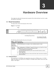
... duplex mode can be half duplex or full duplex. ES-1124 User's Guide 21 Table 1 Panel Connections CONNECTOR DESCRIPTION 24 10/100 Connect these slots for fiber-optic connections to a computer, a hub, an Ethernet switch or router. Figure 6 Front Panel LEDs 10/100 ...Gigabit Ports: Connect these Gigabit Ethernet ports to high-bandwidth backbone network Ethernet switches. • 2 Mini-GBIC Ports: Use mini-GBIC transceivers in these ports to backbone Ethernet switches. 3.1.1 Ethernet Ports The switch has 24 10/100Mbps auto-negotiating, auto-crossover Ethernet ports. CHAPTER 3...
... duplex mode can be half duplex or full duplex. ES-1124 User's Guide 21 Table 1 Panel Connections CONNECTOR DESCRIPTION 24 10/100 Connect these slots for fiber-optic connections to a computer, a hub, an Ethernet switch or router. Figure 6 Front Panel LEDs 10/100 ...Gigabit Ports: Connect these Gigabit Ethernet ports to high-bandwidth backbone network Ethernet switches. • 2 Mini-GBIC Ports: Use mini-GBIC transceivers in these ports to backbone Ethernet switches. 3.1.1 Ethernet Ports The switch has 24 10/100Mbps auto-negotiating, auto-crossover Ethernet ports. CHAPTER 3...
User Guide
Page 22
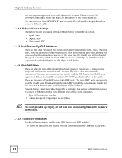
... into the slot with a straight-through or crossover Ethernet cable. 3.1.1.1 Default Ethernet Settings The factory default negotiation settings for details. The switch does not come with the SFP Transceiver MultiSource Agreement (MSA). You must use different transceivers to connect to the optimum Ethernet speed (100...-GBIC ports can be 100Mbps or 1000Mbps and the duplex mode can detect and adjust to Ethernet switches with different types of PCB board facing down. 22 ES-1124 User's Guide The miniGBIC ports have priority over the Gigabit ports. There are two Dual Personality ...
... into the slot with a straight-through or crossover Ethernet cable. 3.1.1.1 Default Ethernet Settings The factory default negotiation settings for details. The switch does not come with the SFP Transceiver MultiSource Agreement (MSA). You must use different transceivers to connect to the optimum Ethernet speed (100...-GBIC ports can be 100Mbps or 1000Mbps and the duplex mode can detect and adjust to Ethernet switches with different types of PCB board facing down. 22 ES-1124 User's Guide The miniGBIC ports have priority over the Gigabit ports. There are two Dual Personality ...
User Guide
Page 23
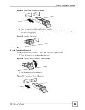
Figure 10 Transceiver Removal Example ES-1124 User's Guide 23 Figure 7 Transceiver Installation Example Chapter 3 Hardware Overview 2 Press the transceiver firmly until it is functioning properly. Check the LEDs to remove a mini GBIC transceiver (SFP module). 1 Open the transceiver's latch (latch styles vary). Figure 9 Opening the Transceiver's Latch Example 2 Pull the transceiver out of the slot. Figure 8 Installed Transceiver 3.1.3.2 Transceiver Removal Use the following steps to verify that it clicks into place. 3 The switch automatically detects the installed transceiver.
Figure 10 Transceiver Removal Example ES-1124 User's Guide 23 Figure 7 Transceiver Installation Example Chapter 3 Hardware Overview 2 Press the transceiver firmly until it is functioning properly. Check the LEDs to remove a mini GBIC transceiver (SFP module). 1 Open the transceiver's latch (latch styles vary). Figure 9 Opening the Transceiver's Latch Example 2 Pull the transceiver out of the slot. Figure 8 Installed Transceiver 3.1.3.2 Transceiver Removal Use the following steps to verify that it clicks into place. 3 The switch automatically detects the installed transceiver.
User Guide
Page 24
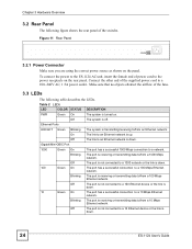
... the rear panel of the switche. Table 2 LEDs LED COLOR STATUS DESCRIPTION PWR Green On The system is receiving or transmitting data to the power receptacle on the panel. Connect the other end of power cord to /from an Ethernet network. To connect the power to the ES-1124 AC unit, insert the... female end of the supplied power cord to a 100 Ethernet device or the link is down . 24 ES-1124 User's Guide Off The port is not connected to a 100~240V AC, 1.5A power outlet. Off The port is not connected to a 10 Ethernet device ...
... the rear panel of the switche. Table 2 LEDs LED COLOR STATUS DESCRIPTION PWR Green On The system is receiving or transmitting data to the power receptacle on the panel. Connect the other end of power cord to /from an Ethernet network. To connect the power to the ES-1124 AC unit, insert the... female end of the supplied power cord to a 100 Ethernet device or the link is down . 24 ES-1124 User's Guide Off The port is not connected to a 100~240V AC, 1.5A power outlet. Off The port is not connected to a 10 Ethernet device ...
User Guide
Page 25
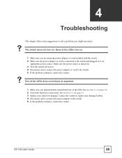
...sure you understand the normal behavior of the LEDs turn on page 24. 2 Check the hardware connections. ES-1124 User's Guide 25 Make sure the power source is connected to the switch and plugged in to the switch. 5 If the problem continues, contact the vendor. See Section 3.1 on . 4 Disconnect and re-...to solve problems you are using the power adaptor or cord included with the switch. 2 Make sure the power adaptor or cord is turned on. 3 Turn the switch off and on page 21. 3 Inspect your cables for damage. V The switch does not turn on. 1 Make sure you might encounter. CHAPTER 4 ...
...sure you understand the normal behavior of the LEDs turn on page 24. 2 Check the hardware connections. ES-1124 User's Guide 25 Make sure the power source is connected to the switch and plugged in to the switch. 5 If the problem continues, contact the vendor. See Section 3.1 on . 4 Disconnect and re-...to solve problems you are using the power adaptor or cord included with the switch. 2 Make sure the power adaptor or cord is turned on. 3 Turn the switch off and on page 21. 3 Inspect your cables for damage. V The switch does not turn on. 1 Make sure you might encounter. CHAPTER 4 ...

User Guide
Page 29
...for abnormal packet filtering Other Features No-Blocking full wire speed architecture Fanless design EMC FCC Part 15 (Class A) CE EMC (Class A) ES-1124 User's Guide 29 Table 3 LEDs Hardware Specifications PWR Per Gigabit port: 1000, LNK/ACT Per mini-GBIC port: LNK, ACT Per ... Watt Max. Frame size: 1522 bytes IEEE 802.1p support for two outgoing priority queues Broadcast Storm Control Supports automatic address learning Store-and-forwarding switching architecture for full duplex (IEEE 802.3x) Operation Temperature 0º C ~ 45º C Operation Humidity 10% ~ 90% RH Table ...
...for abnormal packet filtering Other Features No-Blocking full wire speed architecture Fanless design EMC FCC Part 15 (Class A) CE EMC (Class A) ES-1124 User's Guide 29 Table 3 LEDs Hardware Specifications PWR Per Gigabit port: 1000, LNK/ACT Per mini-GBIC port: LNK, ACT Per ... Watt Max. Frame size: 1522 bytes IEEE 802.1p support for two outgoing priority queues Broadcast Storm Control Supports automatic address learning Store-and-forwarding switching architecture for full duplex (IEEE 802.3x) Operation Temperature 0º C ~ 45º C Operation Humidity 10% ~ 90% RH Table ...

User Guide
Page 38
...Internet Assigned Number Authority (IANA) reserved this is the case, it can assign any other hand, if you are told otherwise. Your switch will assign you a dynamic IP address when the connection is through an ISP, the ISP can obtain your Internet access is established.... have a single user account and the ISP will compute the subnet mask automatically based on the switch. The subnet mask specifies the network number portion of IP Address Space. 38 ES-1124 User's Guide For more information on your network administrator assigns you are isolated from a private network...
...Internet Assigned Number Authority (IANA) reserved this is the case, it can assign any other hand, if you are told otherwise. Your switch will assign you a dynamic IP address when the connection is through an ISP, the ISP can obtain your Internet access is established.... have a single user account and the ISP will compute the subnet mask automatically based on the switch. The subnet mask specifies the network number portion of IP Address Space. 38 ES-1124 User's Guide For more information on your network administrator assigns you are isolated from a private network...
User Guide
Page 40
... extent it shall deem necessary to restore the product or components to proper operating 40 ES-1124 User's Guide During the warranty period, and upon proof of purchase, should the product... Warning: Notices Changes or modifications not expressly approved by the party responsible for a Class A digital switch, pursuant to Part 15 of up to two years from this product is a class A product. ...and used in which case the user may cause radio interference in a commercial environment. ZyXEL Limited Warranty ZyXEL warrants to the original end user (purchaser) that product's page. 3 Select the...
... extent it shall deem necessary to restore the product or components to proper operating 40 ES-1124 User's Guide During the warranty period, and upon proof of purchase, should the product... Warning: Notices Changes or modifications not expressly approved by the party responsible for a Class A digital switch, pursuant to Part 15 of up to two years from this product is a class A product. ...and used in which case the user may cause radio interference in a commercial environment. ZyXEL Limited Warranty ZyXEL warrants to the original end user (purchaser) that product's page. 3 Select the...