Owner's Manual
Page 2
...: Yamaha strives to update existing units. English SPECIAL MESSAGE SECTION This product utilizes an external power supply (adapter). WARNING: Do not place this product to the disposal of the product. For longer extension cords, consult a local electrician. The model number, serial number, power requirements, etc., are not covered by Yamaha. NOTICE: Service charges incurred due to lack of knowledge relating to how a function or effect works (when...
...: Yamaha strives to update existing units. English SPECIAL MESSAGE SECTION This product utilizes an external power supply (adapter). WARNING: Do not place this product to the disposal of the product. For longer extension cords, consult a local electrician. The model number, serial number, power requirements, etc., are not covered by Yamaha. NOTICE: Service charges incurred due to lack of knowledge relating to how a function or effect works (when...
Owner's Manual
Page 3
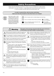
... the instructions. Before using the AC adapter, do so with this instrument, and to protect you and others from the outlet. Repairs or part replacement should not be exposed to moisture (bathroom, on how to properly use . Do not use your vibraphone in a safe manner. When using the vibraphone, please thoroughly read the following instructions and the Owner's Manual. Bumping into the drive unit...
... the instructions. Before using the AC adapter, do so with this instrument, and to protect you and others from the outlet. Repairs or part replacement should not be exposed to moisture (bathroom, on how to properly use . Do not use your vibraphone in a safe manner. When using the vibraphone, please thoroughly read the following instructions and the Owner's Manual. Bumping into the drive unit...
Owner's Manual
Page 4
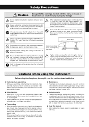
.... Attempting to hold the AC adapter when connecting or disconnecting the power. Tighten bolts securely after determining the desired height. When replacing consumable parts, please consult with poor ventilation. Improper assembly of time. Never use the mallets for any other than playing the instrument. sumable parts and their pitch. • Treating the controller or driver roughly can result in the instrument overturning and create a danger...
.... Attempting to hold the AC adapter when connecting or disconnecting the power. Tighten bolts securely after determining the desired height. When replacing consumable parts, please consult with poor ventilation. Improper assembly of time. Never use the mallets for any other than playing the instrument. sumable parts and their pitch. • Treating the controller or driver roughly can result in the instrument overturning and create a danger...

Owner's Manual
Page 5
... SLOW MOTOR SPEED FAST POWER ON OFF re w q q POWER Switch Turns the power on and flashes while the fan is turned on and off. w MOTOR SPEED Slider Controls the fan rotation speed. t DC 12-15V IN Jack y MOTOR OUT Terminal u MOTOR IN Terminal i 8P DIN Cable o AC Adapter 20 ● Controller (Right Side) ● Driver (Player Side) r START/STOP Button Starts and stops...
... SLOW MOTOR SPEED FAST POWER ON OFF re w q q POWER Switch Turns the power on and flashes while the fan is turned on and off. w MOTOR SPEED Slider Controls the fan rotation speed. t DC 12-15V IN Jack y MOTOR OUT Terminal u MOTOR IN Terminal i 8P DIN Cable o AC Adapter 20 ● Controller (Right Side) ● Driver (Player Side) r START/STOP Button Starts and stops...
Owner's Manual
Page 6
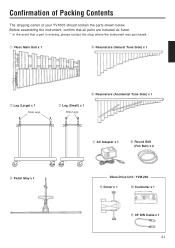
Confirmation of Packing Contents The shipping carton of your YV1605 should contain the parts shown below. Before assembling the instrument, confirm that all parts are included as listed. * In the event that a part is missing, please contact the shop where the instrument was purchased. q Vibes Main Unit x 1 t Resonators (Natural Tone Side) x 1 w Leg (Large) x 1 Slide Legs y Resonators (Accidental Tone Side) x 1 e Leg (Small) x 1 Slide Legs u AC Adapter x 1 i Round Belt (Fan Belt) x 2 r Pedal Stay x 1 Vibes Drive Unit: YVM-200 o Driver x 1 !0 Controller x 1 !1 8P DIN Cable x 1 21
Confirmation of Packing Contents The shipping carton of your YV1605 should contain the parts shown below. Before assembling the instrument, confirm that all parts are included as listed. * In the event that a part is missing, please contact the shop where the instrument was purchased. q Vibes Main Unit x 1 t Resonators (Natural Tone Side) x 1 w Leg (Large) x 1 Slide Legs y Resonators (Accidental Tone Side) x 1 e Leg (Small) x 1 Slide Legs u AC Adapter x 1 i Round Belt (Fan Belt) x 2 r Pedal Stay x 1 Vibes Drive Unit: YVM-200 o Driver x 1 !0 Controller x 1 !1 8P DIN Cable x 1 21

Owner's Manual
Page 7
... Loosen the slide leg fixing bolts of the main unit. (All four slide legs are identical.) Slide Legs Tighten 22 We recommend to you to assemble the instrument on the floor. Slide Legs Slide Leg Fixing Bolt Slide Leg Fixing Bolt Slide Leg Fixing Bolt Leg (Large) Leg (Small) x Place the ... rug or carpet to avoid scratches in a location with sufficient space. c Screw each slide leg into the screw hole at least 2 persons in the tone bars. Assembly For safety, assembly should be performed by at the bottom side of the large and the small leg, and remove the four slide legs.
... Loosen the slide leg fixing bolts of the main unit. (All four slide legs are identical.) Slide Legs Tighten 22 We recommend to you to assemble the instrument on the floor. Slide Legs Slide Leg Fixing Bolt Slide Leg Fixing Bolt Slide Leg Fixing Bolt Leg (Large) Leg (Small) x Place the ... rug or carpet to avoid scratches in a location with sufficient space. c Screw each slide leg into the screw hole at least 2 persons in the tone bars. Assembly For safety, assembly should be performed by at the bottom side of the large and the small leg, and remove the four slide legs.
Owner's Manual
Page 8
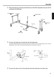
... will be positioned as illustrated. Assembly v Place the large leg, small leg and pedal stay so that after assembly each part will go (aligning the notch with the fixing bolt) and tighten the fixing bolt securely. Low Sound Side Leg (Large) Audience Side Pedal Pedal Stay Leg (Small) High Sound Side Player Side b Connect the large leg and small leg...
... will be positioned as illustrated. Assembly v Place the large leg, small leg and pedal stay so that after assembly each part will go (aligning the notch with the fixing bolt) and tighten the fixing bolt securely. Low Sound Side Leg (Large) Audience Side Pedal Pedal Stay Leg (Small) High Sound Side Player Side b Connect the large leg and small leg...
Owner's Manual
Page 9
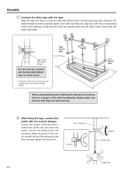
... the rod connector. Always make sure that the slide legs slide into the fitting of the fixing bolt, and then securely tighten the fixing bolt. Do not touch the notched part during height adjustment to extend the center rod...Assembly m Connect the slide legs with the sustain damper. High Sound Side When a slide leg fixing bolt is tightened in the center rod with upper flange. Low Sound Side , After fixing the legs, connect the pedal with the legs. Adjust to the standard height setting. Rod Connector Groove Tighten Center Rod Pedal Rod 24 Align the legs from the tone...
... the rod connector. Always make sure that the slide legs slide into the fitting of the fixing bolt, and then securely tighten the fixing bolt. Do not touch the notched part during height adjustment to extend the center rod...Assembly m Connect the slide legs with the sustain damper. High Sound Side When a slide leg fixing bolt is tightened in the center rod with upper flange. Low Sound Side , After fixing the legs, connect the pedal with the legs. Adjust to the standard height setting. Rod Connector Groove Tighten Center Rod Pedal Rod 24 Align the legs from the tone...

Owner's Manual
Page 10
... (rubber). * Make sure not to confuse the natural tone side and accidental tone side resonators. * Take care not to bump the resonators against the legs etc. 1 First, place the high sound side onto the corre- Resonator Holders 25 Attach the resonators. Resonator Holders Low Sound Side Accidental Tone Side Resonators z x High Sound Side 2 To engage the low sound side, lift...
... (rubber). * Make sure not to confuse the natural tone side and accidental tone side resonators. * Take care not to bump the resonators against the legs etc. 1 First, place the high sound side onto the corre- Resonator Holders 25 Attach the resonators. Resonator Holders Low Sound Side Accidental Tone Side Resonators z x High Sound Side 2 To engage the low sound side, lift...
Owner's Manual
Page 11
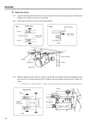
...Assembly ⁄0 Attach the driver. 10-1 Loosen the fixing bolts at the bottom of rails (2) and (3) on either side are positioned directly below the fan side pulleys. Engage the two side mounts on the driver securely with the fittings, and then tighten the fixing bolts to fasten the driver. * Set the driver... so that the pulleys on the high sound side, and slide both fittings in the direction of the low sound side. 10-2 Fully insert the driver mount into the support fitting. 10-1 Bottom View Rail (2) Slide the ...
...Assembly ⁄0 Attach the driver. 10-1 Loosen the fixing bolts at the bottom of rails (2) and (3) on either side are positioned directly below the fan side pulleys. Engage the two side mounts on the driver securely with the fittings, and then tighten the fixing bolts to fasten the driver. * Set the driver... so that the pulleys on the high sound side, and slide both fittings in the direction of the low sound side. 10-2 Fully insert the driver mount into the support fitting. 10-1 Bottom View Rail (2) Slide the ...
Owner's Manual
Page 12
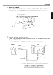
... a time. W5 128092 Part Name 8P DIN Cable Specification L=220 27 Assembly ⁄1 Attach the controller. Connect the MOTOR IN terminal of the driver with the screw next to the jack. There are two controller mounting pins on the plug with the MOTOR OUT terminal of rail (1). To connect align the arrow mark ( ) on the high sound side of the controller using the supplied 8P DIN cable*.
... a time. W5 128092 Part Name 8P DIN Cable Specification L=220 27 Assembly ⁄1 Attach the controller. Connect the MOTOR IN terminal of the driver with the screw next to the jack. There are two controller mounting pins on the plug with the MOTOR OUT terminal of rail (1). To connect align the arrow mark ( ) on the high sound side of the controller using the supplied 8P DIN cable*.
Owner's Manual
Page 13
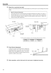
W5 128070 Part Name Fan Belt Specification 3ØL236 ⁄4 Pedal Stroke Adjustment Loosen the center rod fixing bolts to adjust the protruding length of the driver pulley. * Note For Service Personnel If the belt cannot be ordered: Part No. Tighten the screws securely after adjustment. Assembly ⁄3 Attach the round belt (fan belt)*. Slip the round belt (fan belt) over the...
W5 128070 Part Name Fan Belt Specification 3ØL236 ⁄4 Pedal Stroke Adjustment Loosen the center rod fixing bolts to adjust the protruding length of the driver pulley. * Note For Service Personnel If the belt cannot be ordered: Part No. Tighten the screws securely after adjustment. Assembly ⁄3 Attach the round belt (fan belt)*. Slip the round belt (fan belt) over the...
Owner's Manual
Page 14
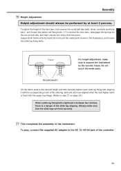
...leg flange. (Refer to step m on the low sound side, and then unhook the string from the post.) Support both frame ends by at least 2 persons. Do not touch the metal parts. Frame For height adjustment, make sure that the slide legs are aligned when the...notch are held securely. ⁄7 This completes the assembly of the instrument. To play, connect the supplied AC adapter to support the instrument by the wooden frame. Assembly ⁄6 Height Adjustment Height adjustment should always be performed by hand (do not touch the metal parts shown in between two notches, there is a ...
...leg flange. (Refer to step m on the low sound side, and then unhook the string from the post.) Support both frame ends by at least 2 persons. Do not touch the metal parts. Frame For height adjustment, make sure that the slide legs are aligned when the...notch are held securely. ⁄7 This completes the assembly of the instrument. To play, connect the supplied AC adapter to support the instrument by the wooden frame. Assembly ⁄6 Height Adjustment Height adjustment should always be performed by hand (do not touch the metal parts shown in between two notches, there is a ...
Owner's Manual
Page 15
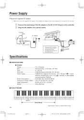
z Connect the small plug of the adapter plug. SPECIFICATIONS YV1605 Range f-f3, 3 Octaves Bars Aluminum Alloy, 1-1/2" wide, 1/2" thick Pitch A = 442 Hz Drive Unit YVM-200 (Pause Controller), 25-145 rpm Power Supply YAMAHA AC Adapter PA-130 (D.C. 12 V, 700 mA North America), PA-D015 (D.C. 15 V, 1 A Europe), or other adapter recommended by the warranty. Power Consumption 2.9 W (PA-130), 3.6 W (PA-D015) Dimensions (Length x Width) ..... 124 x 74 cm (48...
z Connect the small plug of the adapter plug. SPECIFICATIONS YV1605 Range f-f3, 3 Octaves Bars Aluminum Alloy, 1-1/2" wide, 1/2" thick Pitch A = 442 Hz Drive Unit YVM-200 (Pause Controller), 25-145 rpm Power Supply YAMAHA AC Adapter PA-130 (D.C. 12 V, 700 mA North America), PA-D015 (D.C. 15 V, 1 A Europe), or other adapter recommended by the warranty. Power Consumption 2.9 W (PA-130), 3.6 W (PA-D015) Dimensions (Length x Width) ..... 124 x 74 cm (48...


