Owners Manual
Page 2
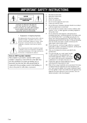
... the NEC that may be connected to the grounding system of the building, as close to the point of cable entry as practical. 1 Read these instructions. 2 Keep these instructions. 3 Heed all warnings. 4 Follow all instructions. 5 Do not use this apparatus during lightning storms or when unused for replacement of Graphical Symbols The lightning flash with arrowhead symbol, within...
... the NEC that may be connected to the grounding system of the building, as close to the point of cable entry as practical. 1 Read these instructions. 2 Keep these instructions. 3 Heed all warnings. 4 Follow all instructions. 5 Do not use this apparatus during lightning storms or when unused for replacement of Graphical Symbols The lightning flash with arrowhead symbol, within...
Owners Manual
Page 3
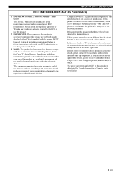
... by Yamaha may cause interference harmful to eliminate the problem by using one of America or its subsidiaries. This equipment generates/uses radio frequencies and, if not installed and used . In the case of other electronic devices. If you can be used according to accessories and/or another product use the product. 2 IMPORTANT: When connecting this product to the instructions found...
... by Yamaha may cause interference harmful to eliminate the problem by using one of America or its subsidiaries. This equipment generates/uses radio frequencies and, if not installed and used . In the case of other electronic devices. If you can be used according to accessories and/or another product use the product. 2 IMPORTANT: When connecting this product to the instructions found...
Owners Manual
Page 4
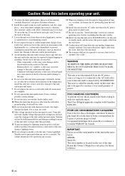
... surrounding temperature changes suddenly. This unit is not disconnected from other than specified is dangerous and may overheat, possibly causing damage. 9 Do not use force on the rear of plug to a wall outlet until all connections are complete. 8 Do not operate this unit must be held responsible for future reference. IMPORTANT Please record the serial number of this unit with a voltage...
... surrounding temperature changes suddenly. This unit is not disconnected from other than specified is dangerous and may overheat, possibly causing damage. 9 Do not use force on the rear of plug to a wall outlet until all connections are complete. 8 Do not operate this unit must be held responsible for future reference. IMPORTANT Please record the serial number of this unit with a voltage...
Owners Manual
Page 5
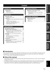
... 10 Connecting a Yamaha iPod universal dock 12 Connecting the indoor FM antenna 12 Connecting the power cable 12 BASIC OPERATION Basic playback operation 13 Enjoying various sound features 14 Enjoying realistic sounds (Sound field program) ........ 14 Enjoying stereo sounds with multi speaker channels (Dolby Pro Logic II 15 Listening at low volume (Night listening mode)......... 15 FM tuning 16 Overview 16 Controls and functions for the FM tuning 16 Basic tuning operation 17 Using station...
... 10 Connecting a Yamaha iPod universal dock 12 Connecting the indoor FM antenna 12 Connecting the power cable 12 BASIC OPERATION Basic playback operation 13 Enjoying various sound features 14 Enjoying realistic sounds (Sound field program) ........ 14 Enjoying stereo sounds with multi speaker channels (Dolby Pro Logic II 15 Listening at low volume (Night listening mode)......... 15 FM tuning 16 Overview 16 Controls and functions for the FM tuning 16 Basic tuning operation 17 Using station...
Owners Manual
Page 6
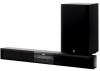
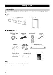
...U YAS-70 (YAS-70CU + YAS-70SPX) CENTER SYSTEM + SUBWOOFER/SYSTEM CONTROL OWNER'S MANUAL 2 En GETTING STARTED Getting started Supplied parts This product consists of the following parts. ■ Units Center system (YAS-70CU) x 1 Subwoofer/system control (YAS-70SPX) x 1 ■ Accessories System control cable (4 m) x 1 Spacer x 2 Speaker cable (4 m) x 2 Remote control x 1 STANDBY/ON MOVIE MUSIC SPORTS GAME INPUT 1 INPUT 2 INPUT 3 DOCK FM INPUT VOLUME MENU MUTE A-E A-E ENTER PRESET AUTO /TUNE /MAN'L MEMORY SW NIGHT DEC MODE CENTER DISP. Before making connections...
...U YAS-70 (YAS-70CU + YAS-70SPX) CENTER SYSTEM + SUBWOOFER/SYSTEM CONTROL OWNER'S MANUAL 2 En GETTING STARTED Getting started Supplied parts This product consists of the following parts. ■ Units Center system (YAS-70CU) x 1 Subwoofer/system control (YAS-70SPX) x 1 ■ Accessories System control cable (4 m) x 1 Spacer x 2 Speaker cable (4 m) x 2 Remote control x 1 STANDBY/ON MOVIE MUSIC SPORTS GAME INPUT 1 INPUT 2 INPUT 3 DOCK FM INPUT VOLUME MENU MUTE A-E A-E ENTER PRESET AUTO /TUNE /MAN'L MEMORY SW NIGHT DEC MODE CENTER DISP. Before making connections...
Owners Manual
Page 7
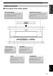
... center system Getting started Front panel display Shows the information about the operational status of this system. (☞ P. 13) INPUT Selects an input source you want to listen to the standby mode. (☞ P. 13) 3 En English Controls the volume of this system or sets it to . (☞ P. 13) STANDBY/ON Turns on . (☞ P. 13) VOLUME +/- VOLUME + STANDBY/ON Power indicator Lights up when this...
... center system Getting started Front panel display Shows the information about the operational status of this system. (☞ P. 13) INPUT Selects an input source you want to listen to the standby mode. (☞ P. 13) 3 En English Controls the volume of this system or sets it to . (☞ P. 13) STANDBY/ON Turns on . (☞ P. 13) VOLUME +/- VOLUME + STANDBY/ON Power indicator Lights up when this...
Owners Manual
Page 9
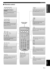
... GAME INPUT 1 INPUT 2 INPUT 3 DOCK FM INPUT VOLUME MENU MUTE A E ENTER A E PRESET AUTO /TUNE /MAN'L MEMORY SW NIGHT DEC. DEC. MODE DIMMER ROOM EQ TEST L R SUR. ROOM EQ Sets the room equalizer. (☞ P. 25) English 5 En MODE Selects a decoder mode (PL II Movie, PL II Music and Auto). (☞ P. 15). INTRODUCTION ■ Remote control MOVIE MUSIC SPORTS GAME Sound field program buttons Select a sound field program. (☞ P. 14) Getting started STANDBY/ON Turns...
... GAME INPUT 1 INPUT 2 INPUT 3 DOCK FM INPUT VOLUME MENU MUTE A E ENTER A E PRESET AUTO /TUNE /MAN'L MEMORY SW NIGHT DEC. DEC. MODE DIMMER ROOM EQ TEST L R SUR. ROOM EQ Sets the room equalizer. (☞ P. 25) English 5 En MODE Selects a decoder mode (PL II Movie, PL II Music and Auto). (☞ P. 15). INTRODUCTION ■ Remote control MOVIE MUSIC SPORTS GAME Sound field program buttons Select a sound field program. (☞ P. 14) Getting started STANDBY/ON Turns...
Owners Manual
Page 11
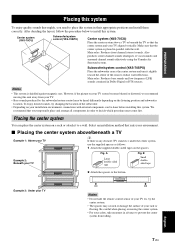
... the procedure below to a wall. Subwoofer/system control (YAS-70SPX) Place the subwoofer near a the center system and turn it to install this system. Center system (YAS-70CU) Subwoofer/system control (YAS-70SPX) Center system (YAS-70CU) Place the center system above /beneath a TV Example 1: Above your rack or flooring. Also produces center channel sounds (dialogues or vocal sounds) and surround channel sounds effectively using the Yamaha Air Surround system.
... the procedure below to a wall. Subwoofer/system control (YAS-70SPX) Place the subwoofer near a the center system and turn it to install this system. Center system (YAS-70CU) Subwoofer/system control (YAS-70SPX) Center system (YAS-70CU) Place the center system above /beneath a TV Example 1: Above your rack or flooring. Also produces center channel sounds (dialogues or vocal sounds) and surround channel sounds effectively using the Yamaha Air Surround system.

Owners Manual
Page 12
... fall . • When connecting the center system, fix the speaker cables in personal injury. 1 Attach the supplied mounting template on a wall and then mark the holes of the center system. 2 Remove the mounting template and then install the commercially available screws at the marks. 22 to 24 mm (7/7" to 15/16") 34 to 36 mm (5/16" to a wall using commercially available screws (#8, Diameter...
... fall . • When connecting the center system, fix the speaker cables in personal injury. 1 Attach the supplied mounting template on a wall and then mark the holes of the center system. 2 Remove the mounting template and then install the commercially available screws at the marks. 22 to 24 mm (7/7" to 15/16") 34 to 36 mm (5/16" to a wall using commercially available screws (#8, Diameter...

Owners Manual
Page 14
... use correct connection cables. ■ Digital connection Notes • The digital jacks of this system support PCM, Dolby Digital, and DTS signal system. • The digital jacks support digital signals of which sampling frequency is 96 kHz or less. [INPUT 1] OPTICAL jack Example 1: DVD player TV DVD player DIGITAL OUT (OPTICAL) Optical digital cable Example 2: TV game console Game console TV OPTICAL DIGITAL OUTPUT Optical digital cable [INPUT 2] COAXIAL jack SYSTEM CONNECTOR FM 75Ω UNBAL 3 L ANTENNA 1 2 DOCK...
... use correct connection cables. ■ Digital connection Notes • The digital jacks of this system support PCM, Dolby Digital, and DTS signal system. • The digital jacks support digital signals of which sampling frequency is 96 kHz or less. [INPUT 1] OPTICAL jack Example 1: DVD player TV DVD player DIGITAL OUT (OPTICAL) Optical digital cable Example 2: TV game console Game console TV OPTICAL DIGITAL OUTPUT Optical digital cable [INPUT 2] COAXIAL jack SYSTEM CONNECTOR FM 75Ω UNBAL 3 L ANTENNA 1 2 DOCK...
Owners Manual
Page 16
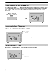
... the subwoofer/system control using the supplied remote control. Connect a Yamaha iPod universal dock to connect a Yamaha iPod universal dock (such as the YDS-10, sold separately) where you made all connections, connect the power cable of your iPod and control playback of the subwoofer/system control. For details, consult the nearest authorized Yamaha dealer or service center. Connecting the power cable After you can station your iPod using its dedicated cable. SYSTEM CONNECTOR FM 75Ω UNBAL 3 L ANTENNA 1 2 DOCK R ANALOG INPUT OPTICAL COAXIAL R L SPEAKERS...
... the subwoofer/system control using the supplied remote control. Connect a Yamaha iPod universal dock to connect a Yamaha iPod universal dock (such as the YDS-10, sold separately) where you made all connections, connect the power cable of your iPod and control playback of the subwoofer/system control. For details, consult the nearest authorized Yamaha dealer or service center. Connecting the power cable After you can station your iPod using its dedicated cable. SYSTEM CONNECTOR FM 75Ω UNBAL 3 L ANTENNA 1 2 DOCK R ANALOG INPUT OPTICAL COAXIAL R L SPEAKERS...
Owners Manual
Page 17
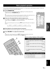
... cable connections (see pages 9 to 12) and remote control preparation (page 6), follow the procedure below to the standby mode, press STANDBY/ON again. y To turn off the volume temporarily, press MUTE. The input source changes as CD audio with a sound field program ☞ P. 14 • To enjoy stereo sounds such as follows: INPUT 1 INPUT 2 INPUT 3 DOCK FM Enjoy Sounds 3 Start playback on and the power indicator lights up. to select the DVD player...
... cable connections (see pages 9 to 12) and remote control preparation (page 6), follow the procedure below to the standby mode, press STANDBY/ON again. y To turn off the volume temporarily, press MUTE. The input source changes as CD audio with a sound field program ☞ P. 14 • To enjoy stereo sounds such as follows: INPUT 1 INPUT 2 INPUT 3 DOCK FM Enjoy Sounds 3 Start playback on and the power indicator lights up. to select the DVD player...

Owners Manual
Page 22
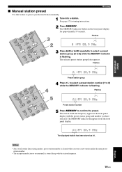
... MUSIC MOVIE INPUT INPUT 1 INPUT 3 2 INPUT FM VOLUME MUTE 1 DOCK MENU A-E A-E ENTER 2 PR/ETSUENTE AU/MTAON'L MEMORY SW NIGHT DEC MODE CENTER OOM EQ UR 1 Press FM to the memory by using the automatic preset station feature. The preset station number as well as the MEMORY and AUTO indicators flashes. Flash AUTO MEMORY A1:FM 88.9 MHz Flashes When automatic preset tuning is completed, the front panel display...
... MUSIC MOVIE INPUT INPUT 1 INPUT 3 2 INPUT FM VOLUME MUTE 1 DOCK MENU A-E A-E ENTER 2 PR/ETSUENTE AU/MTAON'L MEMORY SW NIGHT DEC MODE CENTER OOM EQ UR 1 Press FM to the memory by using the automatic preset station feature. The preset station number as well as the MEMORY and AUTO indicators flashes. Flash AUTO MEMORY A1:FM 88.9 MHz Flashes When automatic preset tuning is completed, the front panel display...
Owners Manual
Page 23
... MEMORY indicator disappears from the front panel display. See page 17 for approximately 10 seconds. English 19 En Flashes MEMORY A :FM 88.9 MHz Preset station group SPORTS MUSIC MOVIE INPUT INPUT 1 INPUT 3 2 INPUT FM VOLUME MUTE 4 DOCK MENU A-E A-E ENTER PR/ETSUENTE AU/MTAON'L MEMORY SW NIGHT DEC MODE CENTER ROOM EQ 5 SUR 4 Press +/- BASIC OPERATION ■ Manual station preset Use this feature to confirm the...
... MEMORY indicator disappears from the front panel display. See page 17 for approximately 10 seconds. English 19 En Flashes MEMORY A :FM 88.9 MHz Preset station group SPORTS MUSIC MOVIE INPUT INPUT 1 INPUT 3 2 INPUT FM VOLUME MUTE 4 DOCK MENU A-E A-E ENTER PR/ETSUENTE AU/MTAON'L MEMORY SW NIGHT DEC MODE CENTER ROOM EQ 5 SUR 4 Press +/- BASIC OPERATION ■ Manual station preset Use this feature to confirm the...
Owners Manual
Page 24
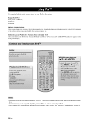
Supported iPod iPod (Click and Wheel) iPod nano iPod mini Battery charge feature This system charges the battery of the iPod stationed to the Yamaha iPod universal dock connected to the instruction manuals of your iPod for iPod™ DOCK Sets this system. MODE DIMMER ROOM EQ TEST L R SUR. Refer to the DOCK terminal of status messages that appear in the front panel display, see the "iPod" section in the front panel display. Stationing your iPod to the...
Supported iPod iPod (Click and Wheel) iPod nano iPod mini Battery charge feature This system charges the battery of the iPod stationed to the Yamaha iPod universal dock connected to the instruction manuals of your iPod for iPod™ DOCK Sets this system. MODE DIMMER ROOM EQ TEST L R SUR. Refer to the DOCK terminal of status messages that appear in the front panel display, see the "iPod" section in the front panel display. Stationing your iPod to the...
Owners Manual
Page 28
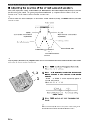
... panel while a test tone is located posterior to the listening position and the sound of surround speaker channel audio reaches the listening position after a few seconds that enables the surround sound field using the center system and the subwoofer/system control. y This system automatically returns to the factory settings, press INPUT on the walls of your listening room. Center system BEAM L (Left surround virtual speaker angle setting...
... panel while a test tone is located posterior to the listening position and the sound of surround speaker channel audio reaches the listening position after a few seconds that enables the surround sound field using the center system and the subwoofer/system control. y This system automatically returns to the factory settings, press INPUT on the walls of your listening room. Center system BEAM L (Left surround virtual speaker angle setting...

Owners Manual
Page 29
... the virtual center speaker channel. STANDBY/ON MOVIE MUSIC SPORTS GAME INPUT 1 INPUT 2 INPUT 3 DOCK FM INPUT VOLUME MENU MUTE A E ENTER A E PRESET AUTO /TUNE /MAN'L MEMORY SW NIGHT DEC. MODE DIMMER ROOM EQ TEST L R SUR. Adjusts the output level of the virtual surround speaker channels. Adjusting the virtual speaker settings Adjusting the characteristics of the tonal quality (ROOM EQ) Use this feature to set the equalizer to...
... the virtual center speaker channel. STANDBY/ON MOVIE MUSIC SPORTS GAME INPUT 1 INPUT 2 INPUT 3 DOCK FM INPUT VOLUME MENU MUTE A E ENTER A E PRESET AUTO /TUNE /MAN'L MEMORY SW NIGHT DEC. MODE DIMMER ROOM EQ TEST L R SUR. Adjusts the output level of the virtual surround speaker channels. Adjusting the virtual speaker settings Adjusting the characteristics of the tonal quality (ROOM EQ) Use this feature to set the equalizer to...
Owners Manual
Page 30
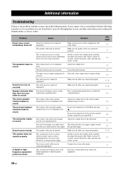
... the volume level of the virtual surround speaker channel by pressing S. You may be shorted. Wait for about 30 seconds, connect the power cable, and then turn on this system. Problem Cause Solution Power turns on one side. The power cable may be connected improperly. Make sure all cables are connected properly. Press sound field program button to the standby mode, and then disconnect the power cable. Increase the output level of the subwoofer...
... the volume level of the virtual surround speaker channel by pressing S. You may be shorted. Wait for about 30 seconds, connect the power cable, and then turn on this system. Problem Cause Solution Power turns on one side. The power cable may be connected improperly. Make sure all cables are connected properly. Press sound field program button to the standby mode, and then disconnect the power cable. Increase the output level of the subwoofer...
Owners Manual
Page 31
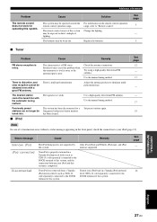
... properly stationed in a Yamaha iPod universal dock (YDS-10, sold separately) connected to the DOCK terminal of this system is distortion, and clear reception cannot be operated outside the remote control operation range. Check the antenna connections. Only iPod (Click and Wheel), iPod nano, and iPod mini are supported. The batteries may be exposed to the DOCK terminal of this system. See page 5 - 5 Problem Cause Remedy FM stereo reception is multi...
... properly stationed in a Yamaha iPod universal dock (YDS-10, sold separately) connected to the DOCK terminal of this system is distortion, and clear reception cannot be operated outside the remote control operation range. Check the antenna connections. Only iPod (Click and Wheel), iPod nano, and iPod mini are supported. The batteries may be exposed to the DOCK terminal of this system. See page 5 - 5 Problem Cause Remedy FM stereo reception is multi...
Owners Manual
Page 32
... on Dolby Surround programmed material; With an abundance of Pro Logic II playback, including separate left , center, and right) and 2 surround stereo channels, Dolby Digital provides five full-range audio channels. Since home conditions, such as room size, wall material, number of sampling (process for the surround speakers, more accurate moving sound effects and surround sound environment are differences in a theater having many speakers and designed for bass effects (called...
... on Dolby Surround programmed material; With an abundance of Pro Logic II playback, including separate left , center, and right) and 2 surround stereo channels, Dolby Digital provides five full-range audio channels. Since home conditions, such as room size, wall material, number of sampling (process for the surround speakers, more accurate moving sound effects and surround sound environment are differences in a theater having many speakers and designed for bass effects (called...


