
CL/QL Series V5.1 Supplementary Manual [English]
Page 1
NOTE • The explanations in this supplementary manual reference the CL5. • Keep in mind that have been added or changed in CL5/CL3/CL1 and QL5/QL1 firmware V5.1. EN CL/QL series V5.1 Supplementary Manual This supplementary manual explains mainly the functions that in the case of the CL3/CL1 or QL5/QL1, certain channels and faders shown in example screens do not exist on those models and will not be shown on those displays. Use it in conjunction with the CL5/CL3/CL1 and QL5/QL1 Owner's Manual and Reference Manual.
NOTE • The explanations in this supplementary manual reference the CL5. • Keep in mind that have been added or changed in CL5/CL3/CL1 and QL5/QL1 firmware V5.1. EN CL/QL series V5.1 Supplementary Manual This supplementary manual explains mainly the functions that in the case of the CL3/CL1 or QL5/QL1, certain channels and faders shown in example screens do not exist on those models and will not be shown on those displays. Use it in conjunction with the CL5/CL3/CL1 and QL5/QL1 Owner's Manual and Reference Manual.
CL/QL Series V5.1 Supplementary Manual [English]
Page 2
Contents I/O devices and external head amps 3 Added supported devices 3 Remotely controlling an external head amp 3 Remotely controlling wireless units 5 Remotely controlling an amp 7 Contents Information This product uses open source software. For information about the license, refer to *** (product name) _OSSLicense_e.pdf, which is included in the downloaded file. 2 V5.1 Supplementary Manual
Contents I/O devices and external head amps 3 Added supported devices 3 Remotely controlling an external head amp 3 Remotely controlling wireless units 5 Remotely controlling an amp 7 Contents Information This product uses open source software. For information about the license, refer to *** (product name) _OSSLicense_e.pdf, which is included in the downloaded file. 2 V5.1 Supplementary Manual
CL/QL Series V5.1 Supplementary Manual [English]
Page 3
... the OUTPUT PATCH window. 3 V5.1 Supplementary Manual I/O devices and external head amps Now supports various Dante devices such as digital wireless receivers, processors, and more from third-party partners, plus NEXO and Yamaha. • Sony DWR-R03D DWX Digital Wireless Receiver • Stagetec NEXUS(XDIP) Multichannel I/O Board • NEXO NXAMPmk2 Powered TD Controller • Yamaha DZR-D series Powered Loudspeakers DXS XLF-D series Powered Subwoofers MRX/MTX series Signal Processors Added supported...
... the OUTPUT PATCH window. 3 V5.1 Supplementary Manual I/O devices and external head amps Now supports various Dante devices such as digital wireless receivers, processors, and more from third-party partners, plus NEXO and Yamaha. • Sony DWR-R03D DWX Digital Wireless Receiver • Stagetec NEXUS(XDIP) Multichannel I/O Board • NEXO NXAMPmk2 Powered TD Controller • Yamaha DZR-D series Powered Loudspeakers DXS XLF-D series Powered Subwoofers MRX/MTX series Signal Processors Added supported...
CL/QL Series V5.1 Supplementary Manual [English]
Page 4
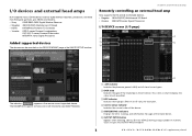
.../QL series, NEXUS must be used to properly set as an approximate value or limit value. 3 FREQUENCY knob/HPF button These controllers switch on or off for each channel. 2 GAIN knob Indicates the gain of MTX-MRX series. 5. I/O DEVICE HA window This screen is displayed when you will be able to adjust it , and use the multifunction knobs (CL series) or the TOUCH AND TURN knob (QL series).
.../QL series, NEXUS must be used to properly set as an approximate value or limit value. 3 FREQUENCY knob/HPF button These controllers switch on or off for each channel. 2 GAIN knob Indicates the gain of MTX-MRX series. 5. I/O DEVICE HA window This screen is displayed when you will be able to adjust it , and use the multifunction knobs (CL series) or the TOUCH AND TURN knob (QL series).
CL/QL Series V5.1 Supplementary Manual [English]
Page 5
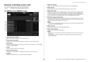
... the audio signal for the receiver. 9 Signal quality meter Displays the quality of the received RF signal. A Battery indicator Shows bars to the console. • As the number of remote control devices is increased at the same time, the meter update frequency decreases. 5 V5.1 Supplementary Manual I /O DEVICE screen (WIRELESS page) 21 B 3 4 5 6 7 8 9 : A 1 Connection status indicator Indicates whether transmitter control is possible or not. 2 Channel name (transmitter) Displays the channel name for setting channel names...
... the audio signal for the receiver. 9 Signal quality meter Displays the quality of the received RF signal. A Battery indicator Shows bars to the console. • As the number of remote control devices is increased at the same time, the meter update frequency decreases. 5 V5.1 Supplementary Manual I /O DEVICE screen (WIRELESS page) 21 B 3 4 5 6 7 8 9 : A 1 Connection status indicator Indicates whether transmitter control is possible or not. 2 Channel name (transmitter) Displays the channel name for setting channel names...
CL/QL Series V5.1 Supplementary Manual [English]
Page 6
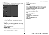
... , and use the multifunction knobs (CL series) or the TOUCH AND TURN knob (QL series). To adjust the value, touch the screen, then press the knob to indicate the remaining battery power. B 1 2 3 4 5 6 7 8 9 : A C 1 Connection status indicator Indicates whether transmitter control is currently set the channel name and HA. In the 4 Diversity mode, the one with the strongest level among A to display the NAME screen for setting channel names on...
... , and use the multifunction knobs (CL series) or the TOUCH AND TURN knob (QL series). To adjust the value, touch the screen, then press the knob to indicate the remaining battery power. B 1 2 3 4 5 6 7 8 9 : A C 1 Connection status indicator Indicates whether transmitter control is currently set the channel name and HA. In the 4 Diversity mode, the one with the strongest level among A to display the NAME screen for setting channel names on...
CL/QL Series V5.1 Supplementary Manual [English]
Page 7
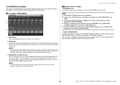
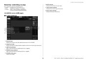
... controlling an amp Now supports the remote controllable devices. • NEXO NXAMPmk2 Powered TD Controller • Yamaha DZR- D series Powered Loudspeakers DXS XLF-D series Powered Subwoofers I /O devices and external head amps 1 7 23 8 4 5 6 1 Channel name Displays the channel name (the speaker preset name for speaker protection is applied. 5 VOLUME setting value Displays the volume. 7 V5.1 Supplementary Manual I /O DEVICE screen (AMP page) For NEXO NXAMPmk2 6 MUTE indicator Indicates the currently set mute status. 7 Control status indicator Indicates the control...
... controlling an amp Now supports the remote controllable devices. • NEXO NXAMPmk2 Powered TD Controller • Yamaha DZR- D series Powered Loudspeakers DXS XLF-D series Powered Subwoofers I /O devices and external head amps 1 7 23 8 4 5 6 1 Channel name Displays the channel name (the speaker preset name for speaker protection is applied. 5 VOLUME setting value Displays the volume. 7 V5.1 Supplementary Manual I /O DEVICE screen (AMP page) For NEXO NXAMPmk2 6 MUTE indicator Indicates the currently set mute status. 7 Control status indicator Indicates the control...
CL/QL Series V5.1 Supplementary Manual [English]
Page 8
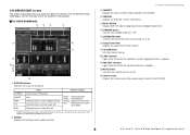
... recalled scene number and title. B MUTE button Switches the channel mute on or off . C Channel name Displays the channel name (the speaker preset name for speaker protection is applied. I/O DEVICE EDIT screen This screen is displayed when you select the desired I/O device in the I /O devices and external head amps 3 CABINET Displays the name of NEXO Setup selected in the NXAMP. 4 VERSION Displays the firmware version of the device. 5 INPUT METER Displays both the input analog input levels and digital input levels...
... recalled scene number and title. B MUTE button Switches the channel mute on or off . C Channel name Displays the channel name (the speaker preset name for speaker protection is applied. I/O DEVICE EDIT screen This screen is displayed when you select the desired I/O device in the I /O devices and external head amps 3 CABINET Displays the name of NEXO Setup selected in the NXAMP. 4 VERSION Displays the firmware version of the device. 5 INPUT METER Displays both the input analog input levels and digital input levels...

CL/QL Series V5.1 Supplementary Manual [English]
Page 9
... Displays the firmware version of the device. 3 STATUS indicator Indicates the status of the screen. 4 INPUT meter Displays both the input analog input levels and digital input levels. 5 HPF ON button (DZR-D series only) Switches the HPF on or off. When an alert occurs, the indicator turns red and the alert contents are displayed at the bottom of the device. A Output level meter Displays the output level of power supply unit Indicator display Green: Normal operation Yellow...
... Displays the firmware version of the device. 3 STATUS indicator Indicates the status of the screen. 4 INPUT meter Displays both the input analog input levels and digital input levels. 5 HPF ON button (DZR-D series only) Switches the HPF on or off. When an alert occurs, the indicator turns red and the alert contents are displayed at the bottom of the device. A Output level meter Displays the output level of power supply unit Indicator display Green: Normal operation Yellow...


