Owner's Manual
Page 5
...Using your headphones 45 Muting the audio output 45 Playing video sources in the background of an audio source 45 Displaying the input source information 46 Using the sleep timer 47 Sound field programs 48 Selecting sound field programs 48 Sound field program descriptions 48 ...Selecting decoders 78 Customizing this unit (MANUAL SETUP).........80 Using SET MENU 84 1 BASIC MENU 85 2 VOLUME MENU 89 3 SOUND MENU 90 4 INPUT MENU 93 5 OPTION MENU 96 Remote control features 100 Controlling this unit, a TV, or other components.......... 100 Setting remote control codes 102 ...
...Using your headphones 45 Muting the audio output 45 Playing video sources in the background of an audio source 45 Displaying the input source information 46 Using the sleep timer 47 Sound field programs 48 Selecting sound field programs 48 Sound field program descriptions 48 ...Selecting decoders 78 Customizing this unit (MANUAL SETUP).........80 Using SET MENU 84 1 BASIC MENU 85 2 VOLUME MENU 89 3 SOUND MENU 90 4 INPUT MENU 93 5 OPTION MENU 96 Remote control features 100 Controlling this unit, a TV, or other components.......... 100 Setting remote control codes 102 ...

Owner's Manual
Page 6
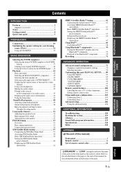
... RMS output power (20 Hz to suit your individual audiovisual system ◆ 5.1 or 7.1-channel additional input jacks for customizing capability ◆ Controlling Yamaha SCENE control signal support component (some models only) working with preset remote control codes capability ◆ Zone... you received all of the following parts. ❏ Remote control ❏ Batteries (2) (AAA, R03, UM-4) ❏ Optimizer microphone ❏ AM loop antenna ❏ Indoor FM antenna 2 En "x.v.Color" video signal transmission capability - channel input ◆ Component video input/output ...
... RMS output power (20 Hz to suit your individual audiovisual system ◆ 5.1 or 7.1-channel additional input jacks for customizing capability ◆ Controlling Yamaha SCENE control signal support component (some models only) working with preset remote control codes capability ◆ Zone... you received all of the following parts. ❏ Remote control ❏ Batteries (2) (AAA, R03, UM-4) ❏ Optimizer microphone ❏ AM loop antenna ❏ Indoor FM antenna 2 En "x.v.Color" video signal transmission capability - channel input ◆ Component video input/output ...

Owner's Manual
Page 9
.... ❏ Speaker cables x 7 ❏ Subwoofer cable x 1 Select a monaural RCA cable. ❏ DVD player x 1 Select DVD player equipped with a composite video input jack. ☞ P. 7 ❏ Video cable x 2 Select an RCA composite video cable. ❏ Digital coaxial audio cable x 1 Step 3: Press SCENE 1 button y You can also connect two ...
.... ❏ Speaker cables x 7 ❏ Subwoofer cable x 1 Select a monaural RCA cable. ❏ DVD player x 1 Select DVD player equipped with a composite video input jack. ☞ P. 7 ❏ Video cable x 2 Select an RCA composite video cable. ❏ Digital coaxial audio cable x 1 Step 3: Press SCENE 1 button y You can also connect two ...
Owner's Manual
Page 10
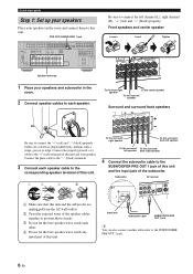
...connect them to this unit. Connect the striped (grooved, etc.) cable to the "+" (red) terminals of this unit. Input jack Subwoofer cable SUBWOOFER PRE OUT 1 jack y You can also connect another subwoofer to connect the "+" (red) and ...back right speaker 4 Connect the subwoofer cable to the SUBWOOFER PRE OUT 1 jack of this unit and the input jack of this unit and your speaker. Connect the plain cable to the "-" (black) terminals. 3 Connect ...left channel (L), right channel (R), "+" (red) and "-" (black) properly. Subwoofer AV receiver PRE OUSTINGLE CENTER DOCK VIDE RROUND SUR.
...connect them to this unit. Connect the striped (grooved, etc.) cable to the "+" (red) terminals of this unit. Input jack Subwoofer cable SUBWOOFER PRE OUT 1 jack y You can also connect another subwoofer to connect the "+" (red) and ...back right speaker 4 Connect the subwoofer cable to the SUBWOOFER PRE OUT 1 jack of this unit and the input jack of this unit and your speaker. Connect the plain cable to the "-" (black) terminals. 3 Connect ...left channel (L), right channel (R), "+" (red) and "-" (black) properly. Subwoofer AV receiver PRE OUSTINGLE CENTER DOCK VIDE RROUND SUR.
Owner's Manual
Page 11
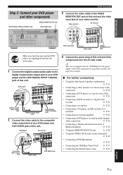
TOTAL C DVR 3 Connect the video cable to the VIDEO MONITOR OUT jack of this unit. Video monitor AV receiver Video input jack VIDEO IN DVD PB OUT IN OUT VCR DVR COMPONENT Y PR VIDEO B DTV/CBL PB MOONUITTOR Y C DVR Video cable VIDEO ...9758; P. 23 • Connecting an external amplifier ☞ P. 24 • Connecting a DVD player via analog multi-channel audio connection ☞ P. 25 • Connecting a Yamaha iPod universal dock or Bluetooth adapter ☞ P. 25 • Using the REMOTE IN/OUT jacks ☞ P. 26 • Using the VIDEO AUX jacks on the...
TOTAL C DVR 3 Connect the video cable to the VIDEO MONITOR OUT jack of this unit. Video monitor AV receiver Video input jack VIDEO IN DVD PB OUT IN OUT VCR DVR COMPONENT Y PR VIDEO B DTV/CBL PB MOONUITTOR Y C DVR Video cable VIDEO ...9758; P. 23 • Connecting an external amplifier ☞ P. 24 • Connecting a DVD player via analog multi-channel audio connection ☞ P. 25 • Connecting a Yamaha iPod universal dock or Bluetooth adapter ☞ P. 25 • Using the REMOTE IN/OUT jacks ☞ P. 26 • Using the VIDEO AUX jacks on the...
Owner's Manual
Page 12
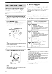
... optimize own status for details. *2 You need to connect the supplied FM and AM antennas to this unit is turned on your favorite input source and sound field program according to the SCENE template that has been assigned to a music disc from the FM radio station. sound...TV program. to adjust the volume. The SCENE templates are 6 ohm speakers, set the input source selector of the video monitor to this unit. ■ About SCENE function Just by pressing one SCENE button, you connect a Yamaha product that has capability of the desired DVD on . Default SCENE button SCENE 1 SCENE...
... optimize own status for details. *2 You need to connect the supplied FM and AM antennas to this unit is turned on your favorite input source and sound field program according to the SCENE template that has been assigned to a music disc from the FM radio station. sound...TV program. to adjust the volume. The SCENE templates are 6 ohm speakers, set the input source selector of the video monitor to this unit. ■ About SCENE function Just by pressing one SCENE button, you connect a Yamaha product that has capability of the desired DVD on . Default SCENE button SCENE 1 SCENE...

Owner's Manual
Page 13
... the speaker parameters for your original SCENE templates ☞ P. 40 This unit is set this unit... See page 29 for details. ■ Using various input sources • Basic controls of this unit ☞ P. 42 • Enjoying FM/AM radio programs ☞ P. 53 • Enjoying XM Satellite ...106 ■ Additional feature • Automatically turning off this unit from the remote control. INTRODUCTION ■ After using this unit to receive infrared signals from the standby mode, press the desired SSCENE buttons (or 6SCENE) or KMAIN ZONE ON/OFF (or HPOWER).
... the speaker parameters for your original SCENE templates ☞ P. 40 This unit is set this unit... See page 29 for details. ■ Using various input sources • Basic controls of this unit ☞ P. 42 • Enjoying FM/AM radio programs ☞ P. 53 • Enjoying XM Satellite ...106 ■ Additional feature • Automatically turning off this unit from the remote control. INTRODUCTION ■ After using this unit to receive infrared signals from the standby mode, press the desired SSCENE buttons (or 6SCENE) or KMAIN ZONE ON/OFF (or HPOWER).

Owner's Manual
Page 14
...MAX. TOTAL 0.8A MAX. and Canada models only) SIRIUS jack (U.S.A. BACK 1 2 SUBWOOFER SIRIUS XM ANTENNA AM GND DVD DTV/CBL 1 2 OPTICAL DIGITAL INPUT FRONT B/ZONE B/ ZONE 2/PRESENCE R EXTRA SP L CD DVD 3 4 COAXIAL FRONT A R L FM 75Ω UNBAL. REMOTE TRIGGER OUT +12V ...IN OUT 15mA MAX. and Canada models only) 2 AUDIO jacks DIGITAL INPUT/OUTPUT jacks 3 MULTI CH INPUT jacks 4 ZONE2 OUT jacks 5 PRE OUT jacks 6 DOCK terminal 7 Video component jacks (VIDEO and S VIDEO) COMPONENT VIDEO jacks 8 ANTENNA terminals...
...MAX. TOTAL 0.8A MAX. and Canada models only) SIRIUS jack (U.S.A. BACK 1 2 SUBWOOFER SIRIUS XM ANTENNA AM GND DVD DTV/CBL 1 2 OPTICAL DIGITAL INPUT FRONT B/ZONE B/ ZONE 2/PRESENCE R EXTRA SP L CD DVD 3 4 COAXIAL FRONT A R L FM 75Ω UNBAL. REMOTE TRIGGER OUT +12V ...IN OUT 15mA MAX. and Canada models only) 2 AUDIO jacks DIGITAL INPUT/OUTPUT jacks 3 MULTI CH INPUT jacks 4 ZONE2 OUT jacks 5 PRE OUT jacks 6 DOCK terminal 7 Video component jacks (VIDEO and S VIDEO) COMPONENT VIDEO jacks 8 ANTENNA terminals...
Owner's Manual
Page 18
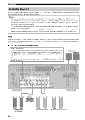
... speaker systems in another room (ZONE B), presence speakers, or Zone 2 speakers. BACK 1 2 SUBWOOFER SIRIUS XM ANTENNA AM GND DVD DTV/CBL 1 2 OPTICAL DIGITAL INPUT FRONT B/ZONE B/ ZONE 2/PRESENCE R EXTRA SP L CD DVD 3 4 COAXIAL FRONT A R L FM 75Ω UNBAL. If this type of this unit. Connect...circuited, "CHECK SP WIRES" appears in the front panel display when you turn on this unit cannot reproduce the input sources accurately. To select the function of insulated cables running side by side. TOTAL 0.8A MAX. Subwoofers (optional) AUDIO L MULTI...
... speaker systems in another room (ZONE B), presence speakers, or Zone 2 speakers. BACK 1 2 SUBWOOFER SIRIUS XM ANTENNA AM GND DVD DTV/CBL 1 2 OPTICAL DIGITAL INPUT FRONT B/ZONE B/ ZONE 2/PRESENCE R EXTRA SP L CD DVD 3 4 COAXIAL FRONT A R L FM 75Ω UNBAL. If this type of this unit. Connect...circuited, "CHECK SP WIRES" appears in the front panel display when you turn on this unit cannot reproduce the input sources accurately. To select the function of insulated cables running side by side. TOTAL 0.8A MAX. Subwoofers (optional) AUDIO L MULTI...

Owner's Manual
Page 19
... DVR IN OUT VCR SUB SB (8CH) SURROUND WOOFER ZONE 2 HDMI OUT FRONT SURROUND SUR. BACK 1 2 SUBWOOFER DVD DTV/CBL 1 2 OPTICAL DIGITAL INPUT FRONT B/ZONE B/ ZONE 2/PRESENCE R EXTRA SP L CD DVD 3 4 COAXIAL FRONT A R L DVD DTV/CBL IN1 IN2 SPEAKERS CENTER SURROUND R L... DVR IN OUT VCR SUB SB (8CH) SURROUND WOOFER ZONE 2 HDMI OUT FRONT SURROUND SUR. BACK 1 2 SUBWOOFER DVD DTV/CBL 1 2 OPTICAL DIGITAL INPUT FRONT B/ZONE B/ ZONE 2/PRESENCE R EXTRA SP L CD DVD 3 4 COAXIAL FRONT A R L DVD DTV/CBL IN1 IN2 SPEAKERS CENTER SURROUND R L...
... DVR IN OUT VCR SUB SB (8CH) SURROUND WOOFER ZONE 2 HDMI OUT FRONT SURROUND SUR. BACK 1 2 SUBWOOFER DVD DTV/CBL 1 2 OPTICAL DIGITAL INPUT FRONT B/ZONE B/ ZONE 2/PRESENCE R EXTRA SP L CD DVD 3 4 COAXIAL FRONT A R L DVD DTV/CBL IN1 IN2 SPEAKERS CENTER SURROUND R L... DVR IN OUT VCR SUB SB (8CH) SURROUND WOOFER ZONE 2 HDMI OUT FRONT SURROUND SUR. BACK 1 2 SUBWOOFER DVD DTV/CBL 1 2 OPTICAL DIGITAL INPUT FRONT B/ZONE B/ ZONE 2/PRESENCE R EXTRA SP L CD DVD 3 4 COAXIAL FRONT A R L DVD DTV/CBL IN1 IN2 SPEAKERS CENTER SURROUND R L...

Owner's Manual
Page 21
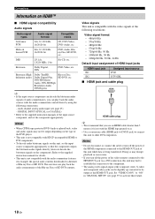
...priority is equipped with up to 96 kHz of sampling frequency. ■ Video jacks This unit has three types of video jacks. Optical input jacks are equipped with. S VIDEO jacks For S-video signals, separated into the luminance (Y) and chrominance (PB, PR) video signals ...jacks. y This unit is given to the left and right analog audio cables. Connection depends on the availability of input jacks on your input components are compatible with digital signals with the video conversion function. PREPARATION Connections Information on jacks and cable plugs Connect...
...priority is equipped with up to 96 kHz of sampling frequency. ■ Video jacks This unit has three types of video jacks. Optical input jacks are equipped with. S VIDEO jacks For S-video signals, separated into the luminance (Y) and chrominance (PB, PR) video signals ...jacks. y This unit is given to the left and right analog audio cables. Connection depends on the availability of input jacks on your input components are compatible with digital signals with the video conversion function. PREPARATION Connections Information on jacks and cable plugs Connect...
Owner's Manual
Page 22
...8226; This unit is not compatible with the audio commentary features (for example, the special audio contents downloaded via Internet) of HDMI input jacks HDMI input jack IN1 IN2 Assigned input source DVD DTV/CBL ■ HDMI jack and cable plug HDMI HDMI cable plug y • We recommend that the component ... DVI-D jack) to connect this unit to "ON" in "MANUAL SETUP" (see page 25) - Refer to the component. • The analog video signals input at the HDMI OUT jack. Notes • Do not disconnect or connect the cable or turn off the power of the HDMI components connected to...
...8226; This unit is not compatible with the audio commentary features (for example, the special audio contents downloaded via Internet) of HDMI input jacks HDMI input jack IN1 IN2 Assigned input source DVD DTV/CBL ■ HDMI jack and cable plug HDMI HDMI cable plug y • We recommend that the component ... DVI-D jack) to connect this unit to "ON" in "MANUAL SETUP" (see page 25) - Refer to the component. • The analog video signals input at the HDMI OUT jack. Notes • Do not disconnect or connect the cable or turn off the power of the HDMI components connected to...

Owner's Manual
Page 23
...only output at the AUDIO output and DIGITAL OUTPUT jacks. VIDEO • Digital video signals input at one of the HDMI IN jacks cannot be output from analog video output jacks. •... only when "S.AUDIO" is as multi-channel PCM, Dolby Digital and DTS signals input at one of resolution are not output at the COMPONENT VIDEO MONITOR OUT jacks. Notes • When... the video signals are input at the HDMI, COMPONENT VIDEO, S VIDEO, and VIDEO jacks, the priority order of the input signals is set to "OTHER" (see page 97) Notes • ...
...only output at the AUDIO output and DIGITAL OUTPUT jacks. VIDEO • Digital video signals input at one of the HDMI IN jacks cannot be output from analog video output jacks. •... only when "S.AUDIO" is as multi-channel PCM, Dolby Digital and DTS signals input at one of resolution are not output at the COMPONENT VIDEO MONITOR OUT jacks. Notes • When... the video signals are input at the HDMI, COMPONENT VIDEO, S VIDEO, and VIDEO jacks, the priority order of the input signals is set to "OTHER" (see page 97) Notes • ...

Owner's Manual
Page 24
... with the automatic audio and video synchronization feature (automatic lip sync feature), this unit to recognize the HDMI audio/video signals being input if they are unplugged from the AC wall outlets. TOTAL C DVR O Optical out TV (or projector) HDMI in Component video... in S-video in Video in the standby mode. Refer to play back HDMI audio signals on this unit. BACK 1 2 SUBWOOFER DVD DTV/CBL 1 2 OPTICAL DIGITAL INPUT FRONT B/ZONE B/ ZONE 2/PRESENCE R EXTRA SP L CD DVD 3 4 COAXIAL FRONT A R L DVD DTV/CBL IN1 IN2 SPEAKERS CENTER SURROUND R L OUT SURROUND...
... with the automatic audio and video synchronization feature (automatic lip sync feature), this unit to recognize the HDMI audio/video signals being input if they are unplugged from the AC wall outlets. TOTAL C DVR O Optical out TV (or projector) HDMI in Component video... in S-video in Video in the standby mode. Refer to play back HDMI audio signals on this unit. BACK 1 2 SUBWOOFER DVD DTV/CBL 1 2 OPTICAL DIGITAL INPUT FRONT B/ZONE B/ ZONE 2/PRESENCE R EXTRA SP L CD DVD 3 4 COAXIAL FRONT A R L DVD DTV/CBL IN1 IN2 SPEAKERS CENTER SURROUND R L OUT SURROUND...

Owner's Manual
Page 25
...AC wall outlets. REMOTE TRIGGER OUT +12V IN OUT 15mA MAX. BACK 1 2 SUBWOOFER SIRIUS XM ANTENNA AM GND DVD DTV/CBL 1 2 OPTICAL DIGITAL INPUT FRONT B/ZONE B/ ZONE 2/PRESENCE R EXTRA SP L CD DVD 3 4 COAXIAL FRONT A R L FM 75Ω UNBAL. PREPARATION Connections Connecting other ... that this unit, connect your other components to make a digital connection to a component other than the default component assigned to each DIGITAL INPUT or DIGITAL OUTPUT jack, select the corresponding setting for "OPTICAL OUT", "OPTICAL IN", or "COAXIAL IN" in "I/O ASSIGNMENT" (see page...
...AC wall outlets. REMOTE TRIGGER OUT +12V IN OUT 15mA MAX. BACK 1 2 SUBWOOFER SIRIUS XM ANTENNA AM GND DVD DTV/CBL 1 2 OPTICAL DIGITAL INPUT FRONT B/ZONE B/ ZONE 2/PRESENCE R EXTRA SP L CD DVD 3 4 COAXIAL FRONT A R L FM 75Ω UNBAL. PREPARATION Connections Connecting other ... that this unit, connect your other components to make a digital connection to a component other than the default component assigned to each DIGITAL INPUT or DIGITAL OUTPUT jack, select the corresponding setting for "OPTICAL OUT", "OPTICAL IN", or "COAXIAL IN" in "I/O ASSIGNMENT" (see page...

Owner's Manual
Page 26
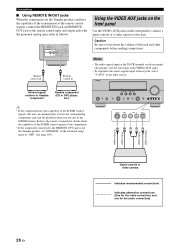
...video out ■ Connecting a set-top box Optical out Audio out Satellite receiver, cable TV receiver or HDTV decoder S-video out Video out Component video out Y PB PR HDMI out O RL Y PB PR V S AUDIO L MULTI CH INPUT FRONT (8CH) CENTER PRE OUT SINGLE CENTER R IN MD/ OUT CD (...FRONT SURROUND SUR. BACK 1 2 SUBWOOFER DVD DTV/CBL CD DVD SIRIUS XM 1 2 3 4 DVD DTV/CBL OUT OPTICAL COAXIAL IN1 IN2 ANTENNA DIGITAL INPUT FRONT B/ZONE B/ SPEAKERS DOCK VIDEO VIDEO S VIDEO DVD DTV/CBL IN OUT DVR IN OUT VCR COMPONENT VIDEO PR A DVD PB Y PR B ...
...video out ■ Connecting a set-top box Optical out Audio out Satellite receiver, cable TV receiver or HDTV decoder S-video out Video out Component video out Y PB PR HDMI out O RL Y PB PR V S AUDIO L MULTI CH INPUT FRONT (8CH) CENTER PRE OUT SINGLE CENTER R IN MD/ OUT CD (...FRONT SURROUND SUR. BACK 1 2 SUBWOOFER DVD DTV/CBL CD DVD SIRIUS XM 1 2 3 4 DVD DTV/CBL OUT OPTICAL COAXIAL IN1 IN2 ANTENNA DIGITAL INPUT FRONT B/ZONE B/ SPEAKERS DOCK VIDEO VIDEO S VIDEO DVD DTV/CBL IN OUT DVR IN OUT VCR COMPONENT VIDEO PR A DVD PB Y PR B ...

Owner's Manual
Page 27
... Connecting audio components Connections Notes • To make a digital connection to a component other than the default component assigned to each the DIGITAL INPUT jack, select the corresponding setting for the audio connection) English 23 En CD recorder, MD recorder or tape deck Audio out Audio in ...out Audio out CD player indicates recommended connections indicates alternative connections (One for "OPTICAL IN", or "COAXIAL IN" in LR LR AUDIO L MULTI CH INPUT FRONT (8CH) CENTER PRE OU R IN MD/ OUT CD (PLAY) CD-R (REC) DVD DTV/CBL IN OUT DVR IN OUT VCR SUB...
... Connecting audio components Connections Notes • To make a digital connection to a component other than the default component assigned to each the DIGITAL INPUT jack, select the corresponding setting for the audio connection) English 23 En CD recorder, MD recorder or tape deck Audio out Audio in ...out Audio out CD player indicates recommended connections indicates alternative connections (One for "OPTICAL IN", or "COAXIAL IN" in LR LR AUDIO L MULTI CH INPUT FRONT (8CH) CENTER PRE OU R IN MD/ OUT CD (PLAY) CD-R (REC) DVD DTV/CBL IN OUT DVR IN OUT VCR SUB...

Owner's Manual
Page 29
...to "Using iPod™" on the rear panel that you to connect a Yamaha iPod universal dock (such as YDS-10, sold separately). We recommend that allows you connect at the MULTI CH INPUT jacks to accommodate for playback of this unit using this feature. Notes &#...in "MULTI CH" (see page 95). ■ Connecting a Yamaha iPod universal dock or Bluetooth adapter This unit is equipped with 6 additional input jacks (left and right FRONT, CENTER, left and right input jacks for discrete multi-channel input from a multi-format player, external decoder, sound processor or preamplifier....
...to "Using iPod™" on the rear panel that you to connect a Yamaha iPod universal dock (such as YDS-10, sold separately). We recommend that allows you connect at the MULTI CH INPUT jacks to accommodate for playback of this unit using this feature. Notes &#...in "MULTI CH" (see page 95). ■ Connecting a Yamaha iPod universal dock or Bluetooth adapter This unit is equipped with 6 additional input jacks (left and right FRONT, CENTER, left and right input jacks for discrete multi-channel input from a multi-format player, external decoder, sound processor or preamplifier....
Owner's Manual
Page 30
... signals, connect the REMOTE IN jack and REMOTE OUT jack to the remote control input and output jack with the monaural analog mini cable as the input source. Notes • The audio signals input at the DOCK terminal on the front panel to connect a game console or a... the capability of this unit. Remote control out Remote control in the advanced setup menu to "OFF" (see page 109). Infrared signal receiver or Yamaha component Yamaha component (CD or DVD player, etc.) VOLUME SPEAKERS EDIT SEARCH MODE BAND CATEGORY A/B/C/D/E PRESET/TUNING/CH MEMORY INFO ZONE 2 ON/OFF ...
... signals, connect the REMOTE IN jack and REMOTE OUT jack to the remote control input and output jack with the monaural analog mini cable as the input source. Notes • The audio signals input at the DOCK terminal on the front panel to connect a game console or a... the capability of this unit. Remote control out Remote control in the advanced setup menu to "OFF" (see page 109). Infrared signal receiver or Yamaha component Yamaha component (CD or DVD player, etc.) VOLUME SPEAKERS EDIT SEARCH MODE BAND CATEGORY A/B/C/D/E PRESET/TUNING/CH MEMORY INFO ZONE 2 ON/OFF ...
Owner's Manual
Page 34
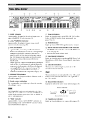
...the U.S.A. A Decoder indicators The respective indicator lights up to the U.S.A. Note The neural indicator is only applicable to show the currently selected input source. and Canada models and CSII indicator is reproducing PCM (Pulse Code Modulation) or DSD (Direct Stream Digital) digital audio signals. ...Bluetooth component is in the paring or the Bluetooth adapter is searching the Bluetooth component (see page 70). • Light up while the Yamaha Bluetooth adapter is connected to the DOCK terminal of this unit function. Connections Front panel display 1 23 4 5 67 89 MULTI CH...
...the U.S.A. A Decoder indicators The respective indicator lights up to the U.S.A. Note The neural indicator is only applicable to show the currently selected input source. and Canada models and CSII indicator is reproducing PCM (Pulse Code Modulation) or DSD (Direct Stream Digital) digital audio signals. ...Bluetooth component is in the paring or the Bluetooth adapter is searching the Bluetooth component (see page 70). • Light up while the Yamaha Bluetooth adapter is connected to the DOCK terminal of this unit function. Connections Front panel display 1 23 4 5 67 89 MULTI CH...


