
Owner's Manual
Page 2
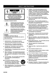
SAFETY INSTRUCTIONS CAUTION RISK OF ELECTRIC SHOCK DO NOT OPEN CAUTION: TO REDUCE THE RISK OF ELECTRIC SHOCK, DO NOT REMOVE COVER (OR BACK). NO USER-SERVICEABLE PARTS INSIDE. All the safety and operating instructions should be cleaned only as marked on the unit and in the operating instructions. Quick stops, excessive force, and uneven surfaces may block the ventilation openings; The unit should be connected to a power supply only of electric shock to . 4 Follow Instructions - The power-supply cord or the plug has been damaged; REFER SERVICING TO QUALIFIED SERVICE ...
SAFETY INSTRUCTIONS CAUTION RISK OF ELECTRIC SHOCK DO NOT OPEN CAUTION: TO REDUCE THE RISK OF ELECTRIC SHOCK, DO NOT REMOVE COVER (OR BACK). NO USER-SERVICEABLE PARTS INSIDE. All the safety and operating instructions should be cleaned only as marked on the unit and in the operating instructions. Quick stops, excessive force, and uneven surfaces may block the ventilation openings; The unit should be connected to a power supply only of electric shock to . 4 Follow Instructions - The power-supply cord or the plug has been damaged; REFER SERVICING TO QUALIFIED SERVICE ...
Owner's Manual
Page 3
...ART 250. PART H) PREPARATION BASIC OPERATION ADVANCED OPERATION FCC INFORMATION (for Class "B" digital devices. Modifications not expressly approved by Yamaha may cause interference harmful to Article 820-40 of other electronic devices. Follow all installations. If the antenna lead-in is found... to be the source of interference, which can not locate the appropriate retailer, please contact Yamaha Electronics Corp., U.S.A. 6660 Orangethorpe Ave, Buena Park, CA 90620. Since hearing damage from excessive volume levels. This product, when...
...ART 250. PART H) PREPARATION BASIC OPERATION ADVANCED OPERATION FCC INFORMATION (for Class "B" digital devices. Modifications not expressly approved by Yamaha may cause interference harmful to Article 820-40 of other electronic devices. Follow all installations. If the antenna lead-in is found... to be the source of interference, which can not locate the appropriate retailer, please contact Yamaha Electronics Corp., U.S.A. 6660 Orangethorpe Ave, Buena Park, CA 90620. Since hearing damage from excessive volume levels. This product, when...
Owner's Manual
Page 4
... might damage the finish. The voltage used must be the same as that specified. 7. Using this unit with a higher voltage than the outlet is observed. 8. YAMAHA will rise rapidly. Do not attempt to wide slot and fully insert. When not planning to use this unit for any damage resulting from the...
... might damage the finish. The voltage used must be the same as that specified. 7. Using this unit with a higher voltage than the outlet is observed. 8. YAMAHA will rise rapidly. Do not attempt to wide slot and fully insert. When not planning to use this unit for any damage resulting from the...
Owner's Manual
Page 5
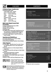
... Processing x Digital Sound Field Processor (DSP) x Dolby Digital Decoder x Dolby Pro Logic Decoder x DTS Decoder x CINEMA DSP: Theater-like Sound Experience by the Combination of YAMAHA DSP Technology and Dolby Digital, Dolby Pro Logic or DTS x Automatic Input Balance Control for Dolby Pro Logic decoding Sophisticated FM/AM Tuner x 40-Station...
... Processing x Digital Sound Field Processor (DSP) x Dolby Digital Decoder x Dolby Pro Logic Decoder x DTS Decoder x CINEMA DSP: Theater-like Sound Experience by the Combination of YAMAHA DSP Technology and Dolby Digital, Dolby Pro Logic or DTS x Automatic Input Balance Control for Dolby Pro Logic decoding Sophisticated FM/AM Tuner x 40-Station...

Owner's Manual
Page 6
Avoid touching the leaked material or letting it come into contact with new ones. Battery Replacement If the remote control operates only when it takes longer than two minutes, the codes preset for the remote control will not be used for replacement. • Be sure the battery polarity is correct. (See the illustration inside of them immediately. Replace all the batteries with clothing, etc. Be sure to the unit, the batteries are included in the direction of the arrow. 2 Insert the batteries (AAA, R03 or UM-4 type) according the polarity markings on the inside the ...
Avoid touching the leaked material or letting it come into contact with new ones. Battery Replacement If the remote control operates only when it takes longer than two minutes, the codes preset for the remote control will not be used for replacement. • Be sure the battery polarity is correct. (See the illustration inside of them immediately. Replace all the batteries with clothing, etc. Be sure to the unit, the batteries are included in the direction of the arrow. 2 Insert the batteries (AAA, R03 or UM-4 type) according the polarity markings on the inside the ...
Owner's Manual
Page 7
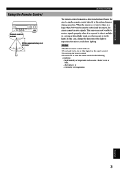
Be sure to avoid direct lighting. Notes • Handle the remote control with care. • Do not spill water, tea or other liquids on the remote control. • Do not drop the remote control. • Do not leave or store the remote control in the following conditions: - When the sensor is covered or there is exposed to receive signals properly when it is a large object between the remote control and the sensor, the sensor cannot receive signals. dusty places; or - In this case, change the direction of the light or reposition the unit to aim the remote control directly at ...
Be sure to avoid direct lighting. Notes • Handle the remote control with care. • Do not spill water, tea or other liquids on the remote control. • Do not drop the remote control. • Do not leave or store the remote control in the following conditions: - When the sensor is covered or there is exposed to receive signals properly when it is a large object between the remote control and the sensor, the sensor cannot receive signals. dusty places; or - In this case, change the direction of the light or reposition the unit to aim the remote control directly at ...
Owner's Manual
Page 8
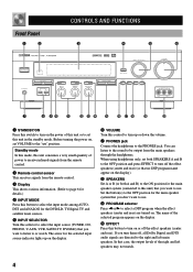
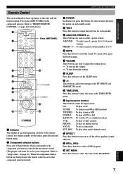
You can listen to the sound to be output from the remote control. 3 Display This shows various information. (Refer to page 6 for details.) 4 INPUT MODE Press this button to select the input mode among AUTO, DTS and ANALOG for the main speaker system (connected to this unit) that case, the output levels of the right and left main speakers. If you want to listen to or watch. Before turning the power on, set both SPEAKERS A and B to the OFF position and press EFFECT to turn up on the display. 6 VOLUME Turn this control to turn off the effect speakers (center and rear) (so that ...
You can listen to the sound to be output from the remote control. 3 Display This shows various information. (Refer to page 6 for details.) 4 INPUT MODE Press this button to select the input mode among AUTO, DTS and ANALOG for the main speaker system (connected to this unit) that case, the output levels of the right and left main speakers. If you want to listen to or watch. Before turning the power on, set both SPEAKERS A and B to the OFF position and press EFFECT to turn up on the display. 6 VOLUME Turn this control to turn off the effect speakers (center and rear) (so that ...
Owner's Manual
Page 9
b) TREBLE Turn this button to store the broadcasting stations. w TAPE/MD MON / EXT. DECODER" appears on the display and switch the function between for storing a broadcasting station (preset tuning) and for tuning. Turn the control to adjust the balance of the output volume from the main speakers. y PRESET/TUNING, EDIT Press this button to turn on or off . i MEMORY (MAN'L/AUTO FM) Press this control clockwise to increase or counterclockwise to decrease the high-frequency response. To use the automatic tuning method, press this button to select one of a group (A to E) of two preset ...
b) TREBLE Turn this button to store the broadcasting stations. w TAPE/MD MON / EXT. DECODER" appears on the display and switch the function between for storing a broadcasting station (preset tuning) and for tuning. Turn the control to adjust the balance of the output volume from the main speakers. y PRESET/TUNING, EDIT Press this button to turn on or off . i MEMORY (MAN'L/AUTO FM) Press this control clockwise to increase or counterclockwise to decrease the high-frequency response. To use the automatic tuning method, press this button to select one of a group (A to E) of two preset ...
Owner's Manual
Page 10
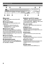
DECODER (or TAPE/MD). 6 g and o indicators " g " lights up when an FM stereo broadcast with Dolby Digital. During this period, the displayed station can be stored in the memory. 9 AUTO indicator This lights up when the unit is in the automatic tuning mode. 0 STEREO indicator This lights up when the built-in Dolby Digital decoder is on and the signals of the selected source are encoded with sufficient signal strength is being received. w SLEEP indicator This lights up when the built-in digital sound field processor is on. 8 MEMORY indicator This flashes for example the name of the ...
DECODER (or TAPE/MD). 6 g and o indicators " g " lights up when an FM stereo broadcast with Dolby Digital. During this period, the displayed station can be stored in the memory. 9 AUTO indicator This lights up when the unit is in the automatic tuning mode. 0 STEREO indicator This lights up when the built-in Dolby Digital decoder is on and the signals of the selected source are encoded with sufficient signal strength is being received. w SLEEP indicator This lights up when the built-in digital sound field processor is on. 8 MEMORY indicator This flashes for example the name of the ...
Owner's Manual
Page 11
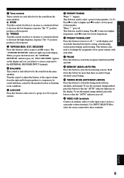
These buttons are used to set the SLEEP timer. 9 +/- u: To turn up the volume d: To turn on and standby mode. 4 TEST Press this button to output the test tone for each speaker. 5 A/B/C/D/E, PRESET +/- r SET MENU Press this button to turn down the volume 8 SLEEP Press this button to select a preset station. DEC.: To play other multi-channel source w EFFECT Press this button to select the items in the SET MENU. Press these buttons which corresponds to the component you press this button, the unit switches between the power on or off the effect speakers (center ...
These buttons are used to set the SLEEP timer. 9 +/- u: To turn up the volume d: To turn on and standby mode. 4 TEST Press this button to output the test tone for each speaker. 5 A/B/C/D/E, PRESET +/- r SET MENU Press this button to turn down the volume 8 SLEEP Press this button to select a preset station. DEC.: To play other multi-channel source w EFFECT Press this button to select the items in the SET MENU. Press these buttons which corresponds to the component you press this button, the unit switches between the power on or off the effect speakers (center ...
Owner's Manual
Page 12
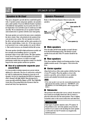
... position, facing slightly inwards, nearly 1.8 m (approx. 6 feet) above the floor. The rear speakers are used for the main source sound plus the effect sounds. The YAMAHA Active Servo Processing Subwoofer System is not used for the effect and surround sounds, and the center speaker is ideal to use of a subwoofer. s Center...
... position, facing slightly inwards, nearly 1.8 m (approx. 6 feet) above the floor. The rear speakers are used for the main source sound plus the effect sounds. The YAMAHA Active Servo Processing Subwoofer System is not used for the effect and surround sounds, and the center speaker is ideal to use of a subwoofer. s Center...
Owner's Manual
Page 13
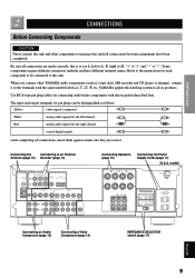
... "+" and "-" to make sure they are correct. The input and output terminals for pin plugs can be connected to this unit and other YAMAHA audio components (such as !, #, $ etc. INTRODUCTION PREPARATION BASIC OPERATION ADVANCED OPERATION CONNECTIONS Before Connecting Components CAUTION Never connect this unit. model)...Component (page 13) IMPEDANCE SELECTOR switch (page 17) APPENDIX English 9 Be sure all connections, check them again to "-". YAMAHA applies this labeling system to an External Antenna (page 10) Decoder (page 14) Connecting Speakers (page 15) Connecting the ...
... "+" and "-" to make sure they are correct. The input and output terminals for pin plugs can be connected to this unit and other YAMAHA audio components (such as !, #, $ etc. INTRODUCTION PREPARATION BASIC OPERATION ADVANCED OPERATION CONNECTIONS Before Connecting Components CAUTION Never connect this unit. model)...Component (page 13) IMPEDANCE SELECTOR switch (page 17) APPENDIX English 9 Be sure all connections, check them again to "-". YAMAHA applies this labeling system to an External Antenna (page 10) Decoder (page 14) Connecting Speakers (page 15) Connecting the ...
Owner's Manual
Page 14
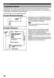
For reception with this adapter to install an antenna that suits your local conditions (distance from any roads as far away from the broadcasting station, interposing buildings and mountains, etc.). Note • Do not connect an outdoor FM antenna and the indoor FM antenna at the same time. You may improve the quality. s Outdoor FM antenna Antenna adapter (included for U.S.A. CONNECTIONS Connecting the Antennas Both AM and FM indoor antennas are included with better sound quality, installing the outdoor FM antenna (commercially available) is only a simple antenna. and ...
For reception with this adapter to install an antenna that suits your local conditions (distance from any roads as far away from the broadcasting station, interposing buildings and mountains, etc.). Note • Do not connect an outdoor FM antenna and the indoor FM antenna at the same time. You may improve the quality. s Outdoor FM antenna Antenna adapter (included for U.S.A. CONNECTIONS Connecting the Antennas Both AM and FM indoor antennas are included with better sound quality, installing the outdoor FM antenna (commercially available) is only a simple antenna. and ...

Owner's Manual
Page 15
However, note that the best reception is connected to this unit. • The AM loop antenna should always be removed from a window. A good earth ground is attached to a metal or steel reinforced wall. Lightly pull the lead wires to confirm a good connection. 4 Attach the loop antenna to the antenna stand. 5 Orient the AM loop antenna so that the reception sensitivity may deteriorate if the antenna is a metal stake driven into the AM ANT and GND terminals. 3 Return the tab to its original position to lock the lead wires. Notes • The AM loop antenna should be placed away...
However, note that the best reception is connected to this unit. • The AM loop antenna should always be removed from a window. A good earth ground is attached to a metal or steel reinforced wall. Lightly pull the lead wires to confirm a good connection. 4 Attach the loop antenna to the antenna stand. 5 Orient the AM loop antenna so that the reception sensitivity may deteriorate if the antenna is a metal stake driven into the AM ANT and GND terminals. 3 Return the tab to its original position to lock the lead wires. Notes • The AM loop antenna should be placed away...
Owner's Manual
Page 16
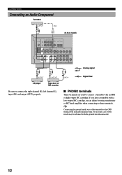
CONNECTIONS Connecting an Audio Component Turntable OUTPUT LR GND (U.S.A. s PHONO terminals These terminals are used to connect a turntable with a low-output MC cartridge, use an inline boosting transformer or MC head amplifier when connecting to these terminals. If you have a turntable with an MM or high-output MC cartridge. model) LR OUTPUT LR LINE OUT LR LINE IN L Analog signal R Signal flow CD player Tape deck or MD recorder Be sure to the GND terminal will normally minimize hum, but in some cases, better results may be obtained with the ground wire disconnected. 12...
CONNECTIONS Connecting an Audio Component Turntable OUTPUT LR GND (U.S.A. s PHONO terminals These terminals are used to connect a turntable with a low-output MC cartridge, use an inline boosting transformer or MC head amplifier when connecting to these terminals. If you have a turntable with an MM or high-output MC cartridge. model) LR OUTPUT LR LINE OUT LR LINE IN L Analog signal R Signal flow CD player Tape deck or MD recorder Be sure to the GND terminal will normally minimize hum, but in some cases, better results may be obtained with the ground wire disconnected. 12...
Owner's Manual
Page 17
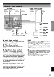
has coaxial or optical digital signal output terminals, they can be heard when connecting your LD player's Dolby Digital RF signal output terminal directly to sampling frequencies of 32 kHz, 44.1 kHz and 48 kHz. 13 APPENDIX English Other cables might not function correctly. Notes • Be sure to attach the covers when the OPTICAL terminals are applicable to this unit's COAXIAL DVD/LD digital signal input terminal. y • The input signal from dust. • If your DVD/LD player, TV/digital TV or satellite tuner, etc. When making connections between the optical digital ...
has coaxial or optical digital signal output terminals, they can be heard when connecting your LD player's Dolby Digital RF signal output terminal directly to sampling frequencies of 32 kHz, 44.1 kHz and 48 kHz. 13 APPENDIX English Other cables might not function correctly. Notes • Be sure to attach the covers when the OPTICAL terminals are applicable to this unit's COAXIAL DVD/LD digital signal input terminal. y • The input signal from dust. • If your DVD/LD player, TV/digital TV or satellite tuner, etc. When making connections between the optical digital ...

Owner's Manual
Page 18
V L R AUDIO OUT R AUDIO OUT L VIDEO OUT Camcorder Connecting to this unit's S VIDEO terminals. Connect the 6-channel audio signal output terminals of the decoder to the EXTERNAL DECODER INPUT terminals of your VCR, TV monitor or DVD/LD player has "S" (highresolution) video terminals, they can be directed to their respective output terminals. Notes • When a source connected to these terminals. Connect the VCR's "S" video input and output terminals to this unit. Connect the DVD/LD player's "S" video output terminal to this unit's S VIDEO MONITOR OUT terminal. ...
V L R AUDIO OUT R AUDIO OUT L VIDEO OUT Camcorder Connecting to this unit's S VIDEO terminals. Connect the 6-channel audio signal output terminals of the decoder to the EXTERNAL DECODER INPUT terminals of your VCR, TV monitor or DVD/LD player has "S" (highresolution) video terminals, they can be directed to their respective output terminals. Notes • When a source connected to these terminals. Connect the VCR's "S" video input and output terminals to this unit. Connect the DVD/LD player's "S" video output terminal to this unit's S VIDEO MONITOR OUT terminal. ...
Owner's Manual
Page 19
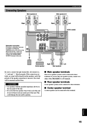
... the polarity of the speaker connections is incorrect, the sound will be connected to these terminals. CAUTIONS • Use speakers with builtin amplifier, including the YAMAHA Active Servo Processing Subwoofer System, connect the input terminal of the subwoofer system to the SUBWOOFER OUTPUT terminal of this unit. INTRODUCTION PREPARATION Connecting Speakers...
... the polarity of the speaker connections is incorrect, the sound will be connected to these terminals. CAUTIONS • Use speakers with builtin amplifier, including the YAMAHA Active Servo Processing Subwoofer System, connect the input terminal of the subwoofer system to the SUBWOOFER OUTPUT terminal of this unit. INTRODUCTION PREPARATION Connecting Speakers...

Owner's Manual
Page 20
y Banana plug connections are also possible. Simply insert the banana plug connector into the hole of each terminal. 3 Return the tab to secure the wire. s Connecting to the REAR and CENTER SPEAKERS terminals Red: positive (+) Black: negative (-) 31 2 1 Open the tab. 2 Insert one bare wire into the hole in the side of each of the speaker cable. 2 Twist the exposed wires of the cable together to prevent short circuits. CONNECTIONS s Speaker cables 10 mm (3/8") 1 Remove approx. 10 mm (3/8") of insulation from each terminal. 3 Tighten the knob to secure the wire. s Connecting ...
y Banana plug connections are also possible. Simply insert the banana plug connector into the hole of each terminal. 3 Return the tab to secure the wire. s Connecting to the REAR and CENTER SPEAKERS terminals Red: positive (+) Black: negative (-) 31 2 1 Open the tab. 2 Insert one bare wire into the hole in the side of each of the speaker cable. 2 Twist the exposed wires of the cable together to prevent short circuits. CONNECTIONS s Speaker cables 10 mm (3/8") 1 Remove approx. 10 mm (3/8") of insulation from each terminal. 3 Tighten the knob to secure the wire. s Connecting ...
Owner's Manual
Page 21
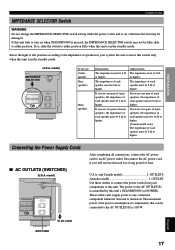
If so, slide the switch to either position. TOTAL SWITCHED If you use Center speaker Rear speakers Main speakers left position according to the impedance of speakers in your components to this unit's STANDBY/ON (or POWER). If you use one pair of main speakers, the impedance of each speaker must be 8 Ω or higher. The impedance of each speaker must be damaged. If you use two pairs of main speakers, the impedance of each speaker must be 16 Ω or higher. [Canada model only] The impedance of each speaker must be 6 Ω or higher. U.S.A. If you use...
If so, slide the switch to either position. TOTAL SWITCHED If you use Center speaker Rear speakers Main speakers left position according to the impedance of speakers in your components to this unit's STANDBY/ON (or POWER). If you use one pair of main speakers, the impedance of each speaker must be 8 Ω or higher. The impedance of each speaker must be damaged. If you use two pairs of main speakers, the impedance of each speaker must be 16 Ω or higher. [Canada model only] The impedance of each speaker must be 6 Ω or higher. U.S.A. If you use...