Owners Manual
Page 2
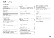
... Playing back tunes from your iPod™/iPhone 33 Connecting the Yamaha iPod universal dock 33 Controlling an iPod/iPhone 33 Playing back tunes from Bluetooth™ components....... 35 Connecting a Yamaha Bluetooth wireless audio receiver 35 Pairing Bluetooth™ components 35 Using Bluetooth™...Displaying/Setting the Advanced Setup menu 53 Setting the impedance of speakers 53 Avoiding crossing remote control signals when using multiple Yamaha receivers 54 Initializing various settings for this unit 54 APPENDIX Troubleshooting 55 General 55 HDMI 57 Tuner (FM/AM 58 Remote...
... Playing back tunes from your iPod™/iPhone 33 Connecting the Yamaha iPod universal dock 33 Controlling an iPod/iPhone 33 Playing back tunes from Bluetooth™ components....... 35 Connecting a Yamaha Bluetooth wireless audio receiver 35 Pairing Bluetooth™ components 35 Using Bluetooth™...Displaying/Setting the Advanced Setup menu 53 Setting the impedance of speakers 53 Avoiding crossing remote control signals when using multiple Yamaha receivers 54 Initializing various settings for this unit 54 APPENDIX Troubleshooting 55 General 55 HDMI 57 Tuner (FM/AM 58 Remote...
Owners Manual
Page 3
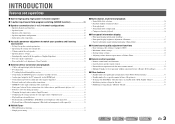
Specifying the settings for 2- Speaker channels and functions ...9 - Speaker cable connection...10 - Speaker distance settings ...42 - INTRODUCTION Features and capabilities ■ Built-in high-quality, high-power 5-channel amplifier ■ 1-button input/sound field program switching (SCENE function 26 ■ Speaker connections for each speaker...42 - Speaker layout...10 - Setting for each speaker 41 - Subwoofer cable connection ...12 ■ Acoustic parameter adjustment to 5.1-channel configurations - Speaker impedance configuration...10 - to match your ...
Specifying the settings for 2- Speaker channels and functions ...9 - Speaker cable connection...10 - Speaker distance settings ...42 - INTRODUCTION Features and capabilities ■ Built-in high-quality, high-power 5-channel amplifier ■ 1-button input/sound field program switching (SCENE function 26 ■ Speaker connections for each speaker...42 - Speaker layout...10 - Setting for each speaker 41 - Subwoofer cable connection ...12 ■ Acoustic parameter adjustment to 5.1-channel configurations - Speaker impedance configuration...10 - to match your ...
Owners Manual
Page 5
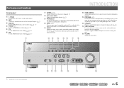
... the input sources in . INFO MEMORY PRESET FM AM TUNING INPUT BD DVD SCENE TV CD TONE CONTROL PROGRAM RADIO STRAIGHT VIDEO AUX PORTABLE VIDEO L AUDIO R VOLUME j kl m n o p En 5 J1 a INTRODUCTION g TUNING jj / ii Changes FM/AM tuner frequencies (☞p. 30). Press either the left or right key repeatedly to this...
... the input sources in . INFO MEMORY PRESET FM AM TUNING INPUT BD DVD SCENE TV CD TONE CONTROL PROGRAM RADIO STRAIGHT VIDEO AUX PORTABLE VIDEO L AUDIO R VOLUME j kl m n o p En 5 J1 a INTRODUCTION g TUNING jj / ii Changes FM/AM tuner frequencies (☞p. 30). Press either the left or right key repeatedly to this...
Owners Manual
Page 6
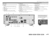
... PB Y MONITOR OUT Y COMPONENT VIDEO VIDEO HDMI 3 HDMI 4 MONITOR OUT OPTICAL AV 1 COAXIAL AV 2 COAXIAL (CD) AV 3 OPTICAL ( TV ) AV 4 AV 5 AV OUT AUDIO 1 AUDIO 2 ANTENNA FM GND SURROU SUBWOOFER e f g h jik l m En 6 d DOCK COMPONENT VIDEO PR HDMI OUT PR (BD/DVD) HDMI 1 HDMI 2 PB PB Y MONITOR OUT...that are compatible with a built-in white to a TV or other external component. Rear panel a DOCK jack For connecting an optional Yamaha iPod universal dock (such as the AV5 or AUDIO1-2 jacks are selected (☞p. 20). b HDMI OUT jack For connecting an HDMI ...
... PB Y MONITOR OUT Y COMPONENT VIDEO VIDEO HDMI 3 HDMI 4 MONITOR OUT OPTICAL AV 1 COAXIAL AV 2 COAXIAL (CD) AV 3 OPTICAL ( TV ) AV 4 AV 5 AV OUT AUDIO 1 AUDIO 2 ANTENNA FM GND SURROU SUBWOOFER e f g h jik l m En 6 d DOCK COMPONENT VIDEO PR HDMI OUT PR (BD/DVD) HDMI 1 HDMI 2 PB PB Y MONITOR OUT...that are compatible with a built-in white to a TV or other external component. Rear panel a DOCK jack For connecting an optional Yamaha iPod universal dock (such as the AV5 or AUDIO1-2 jacks are selected (☞p. 20). b HDMI OUT jack For connecting an HDMI ...

Owners Manual
Page 7
... level. j Speaker indicators Indicate speaker terminals from which signals are selected. Press fINFO repeatedly to cycle through an optional Yamaha iPod universal dock (such as the active input source. f MUTE indicator Flashes when audio is activated (☞p. 8). J1 Input source name HDMI1 Straight VOL. d iPod CHARGE indicator Lights up if corresponding cursors...
... level. j Speaker indicators Indicate speaker terminals from which signals are selected. Press fINFO repeatedly to cycle through an optional Yamaha iPod universal dock (such as the active input source. f MUTE indicator Flashes when audio is activated (☞p. 8). J1 Input source name HDMI1 Straight VOL. d iPod CHARGE indicator Lights up if corresponding cursors...
Owners Manual
Page 8
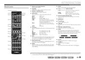
d Input selector Select an input source on and off . J1 DOCK A Yamaha iPod universal dock or Bluetooth wireless audio receiver connected to AM. AM MEMORY PRESET F / G TUNING H / I Sets the FM/AM tuner band to the DOCK TUNER jack. j Cursor B / C / ... menu displays etc. Remote control a b c d e f g h i j k l m SOURCE 1 1 5 TRANSMIT CODE SET SLEEP RECEIVER HDMI 2 3 4 AV 2 3 4 AUDIO 1 2 V-AUX [ A ] [ B ] DOCK TUNER FM AM PRESET TUNING INFO MEMORY MOVIE ENHANCER SUR. HDMI1-4 HDMI1-4 jacks AV1-5 AV1-5 jacks AUDIO1-2 AUDIO1-2 jacks V-AUX Front ...
d Input selector Select an input source on and off . J1 DOCK A Yamaha iPod universal dock or Bluetooth wireless audio receiver connected to AM. AM MEMORY PRESET F / G TUNING H / I Sets the FM/AM tuner band to the DOCK TUNER jack. j Cursor B / C / ... menu displays etc. Remote control a b c d e f g h i j k l m SOURCE 1 1 5 TRANSMIT CODE SET SLEEP RECEIVER HDMI 2 3 4 AV 2 3 4 AUDIO 1 2 V-AUX [ A ] [ B ] DOCK TUNER FM AM PRESET TUNING INFO MEMORY MOVIE ENHANCER SUR. HDMI1-4 HDMI1-4 jacks AV1-5 AV1-5 jacks AUDIO1-2 AUDIO1-2 jacks V-AUX Front ...
Owners Manual
Page 11
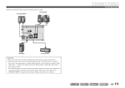
... Connecting speakers En 11 One of two parallel insulated cables. Surround speaker R L Front speaker R L HDMI 4 OR OUT ANTENNA FM GND AM SURROUND CENTER SPEAKERS FRONT AUDIO 2 AUDIO OUT SUBWOOFER Subwoofer Center speaker CAUTION • Remove the AC power cord of this unit is a different color, or has a line running along it, to...
... Connecting speakers En 11 One of two parallel insulated cables. Surround speaker R L Front speaker R L HDMI 4 OR OUT ANTENNA FM GND AM SURROUND CENTER SPEAKERS FRONT AUDIO 2 AUDIO OUT SUBWOOFER Subwoofer Center speaker CAUTION • Remove the AC power cord of this unit is a different color, or has a line running along it, to...

Owners Manual
Page 12
... CROSSOVER/ HIGH CUT MIN MAX MIN MAX Subwoofer examples En 12 Crossover frequency (if available): Set to the SUBWOOFER jack on this unit with an audio pin cable. 2 Set the subwoofer volume as follows. CONNECTIONS Connecting speakers ■ Connecting the subwoofer 1 Connect the subwoofer input jack to maximum. Connecting the banana...
... CROSSOVER/ HIGH CUT MIN MAX MIN MAX Subwoofer examples En 12 Crossover frequency (if available): Set to the SUBWOOFER jack on this unit with an audio pin cable. 2 Set the subwoofer volume as follows. CONNECTIONS Connecting speakers ■ Connecting the subwoofer 1 Connect the subwoofer input jack to maximum. Connecting the banana...
Owners Manual
Page 13
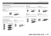
Use video pin cables. Use a stereo mini-plug cable when connecting. COAXIAL jacks These jacks transmit coaxial digital audio signals. Digital audio fiber-optic cable Digital audio pin cable HDMI cable • Use a 19-pin HDMI cable with the HDMI logo. • We recommend using a cable less than 5.0 m long...: luminance (Y), chrominance blue (PB), and chrominance red (PR). Use pin cables for components that you are going to connect. ■ Audio/Video jacks HDMI jacks Digital video and digital sound are transmitted through a single jack. Only use an HDMI cable. ■...
Use video pin cables. Use a stereo mini-plug cable when connecting. COAXIAL jacks These jacks transmit coaxial digital audio signals. Digital audio fiber-optic cable Digital audio pin cable HDMI cable • Use a 19-pin HDMI cable with the HDMI logo. • We recommend using a cable less than 5.0 m long...: luminance (Y), chrominance blue (PB), and chrominance red (PR). Use pin cables for components that you are going to connect. ■ Audio/Video jacks HDMI jacks Digital video and digital sound are transmitted through a single jack. Only use an HDMI cable. ■...

Owners Manual
Page 14
... VIDEO PR PB Y TV OPTICAL AV 1 COAXIAL AV 2 COAXIAL (CD) AV 3 OPTICAL ( TV ) AV 4 AV 5 AV OUT AUDIO 1 AUDIO 2 AUDIO OUT En 14 HDMI OUT, COMPONENT VIDEO or VIDEO. Select the proper connection according to the input signal format supported by matching input/output jacks...COMPONENT VIDEO VIDEO HDMI 3 HDMI 4 MONITOR OUT OPTICAL AV 1 COAXIAL AV 2 COAXIAL (CD) AV 3 OPTICAL ( TV ) AV 4 AV 5 AV OUT AUDIO 1 AUDIO 2 AUDIO OUT HDMI input HDMI HDMI TV COMPONENT VIDEO jacks (MONITOR OUT) VIDEO jack (MONITOR OUT) This unit will receive HDMI, component, or video signals in...
... VIDEO PR PB Y TV OPTICAL AV 1 COAXIAL AV 2 COAXIAL (CD) AV 3 OPTICAL ( TV ) AV 4 AV 5 AV OUT AUDIO 1 AUDIO 2 AUDIO OUT En 14 HDMI OUT, COMPONENT VIDEO or VIDEO. Select the proper connection according to the input signal format supported by matching input/output jacks...COMPONENT VIDEO VIDEO HDMI 3 HDMI 4 MONITOR OUT OPTICAL AV 1 COAXIAL AV 2 COAXIAL (CD) AV 3 OPTICAL ( TV ) AV 4 AV 5 AV OUT AUDIO 1 AUDIO 2 AUDIO OUT HDMI input HDMI HDMI TV COMPONENT VIDEO jacks (MONITOR OUT) VIDEO jack (MONITOR OUT) This unit will receive HDMI, component, or video signals in...
Owners Manual
Page 15
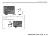
... MONITOR OUT Y COMPONENT VIDEO VIDEO HDMI 3 HDMI 4 MONITOR OUT OPTICAL AV 1 COAXIAL AV 2 COAXIAL (CD) AV 3 OPTICAL AV 5 AV OUT AUDIO 1 AUDIO 2 AUDIO OUT You can control your TV using the SCENE function (☞p. 26). ■ Connecting a video monitor Connect the video pin cable to the TV...MONITOR OUT V OPTICAL AV 1 COAXIAL AV 2 COAXIAL (CD) AV 3 OPTICAL ( TV ) AV 4 AV 5 AV OUT AUDIO 1 AUDIO 2 AUDIO OUT Video input VIDEO V TV ■ Listening to TV audio To transmit sound from the TV to this unit, connect its AV1-5 or AUDIO1-2 jacks to the VIDEO (MONITOR OUT) jack....
... MONITOR OUT Y COMPONENT VIDEO VIDEO HDMI 3 HDMI 4 MONITOR OUT OPTICAL AV 1 COAXIAL AV 2 COAXIAL (CD) AV 3 OPTICAL AV 5 AV OUT AUDIO 1 AUDIO 2 AUDIO OUT You can control your TV using the SCENE function (☞p. 26). ■ Connecting a video monitor Connect the video pin cable to the TV...MONITOR OUT V OPTICAL AV 1 COAXIAL AV 2 COAXIAL (CD) AV 3 OPTICAL ( TV ) AV 4 AV 5 AV OUT AUDIO 1 AUDIO 2 AUDIO OUT Video input VIDEO V TV ■ Listening to TV audio To transmit sound from the TV to this unit, connect its AV1-5 or AUDIO1-2 jacks to the VIDEO (MONITOR OUT) jack....

Owners Manual
Page 16
...DVD player OPTICAL AV 1 COAXIAL AV 2 COAXIAL (CD) AV 3 OPTICAL ( TV ) AV 4 AV 5 AV OUT AUDIO 1 AUDIO 2 AUDIO OUT J 1 : See the section on the external components. HDMI/Audio (Optical) output HDMI HDMI OPTICAL BD/DVD player O O DOCK COMPONENT VIDEO PR HDMI OUT PR (BD/DVD) HDMI HDMI ... Y COMPONENT VIDEO VIDEO HDMI 3 HDMI 4 MONITOR OUT OPTICAL COAXIAL AV 2 COAXIAL (CD) AV 3 OPTICAL ( TV ) AV 4 AV 5 AV OUT AUDIO 1 AUDIO 2 AUDIO OUT 1 Use the dInput selector to select the desired HDMI input source. 2 Press qOPTION to close the Option menu. J1 3 Press jCursor C until...
...DVD player OPTICAL AV 1 COAXIAL AV 2 COAXIAL (CD) AV 3 OPTICAL ( TV ) AV 4 AV 5 AV OUT AUDIO 1 AUDIO 2 AUDIO OUT J 1 : See the section on the external components. HDMI/Audio (Optical) output HDMI HDMI OPTICAL BD/DVD player O O DOCK COMPONENT VIDEO PR HDMI OUT PR (BD/DVD) HDMI HDMI ... Y COMPONENT VIDEO VIDEO HDMI 3 HDMI 4 MONITOR OUT OPTICAL COAXIAL AV 2 COAXIAL (CD) AV 3 OPTICAL ( TV ) AV 4 AV 5 AV OUT AUDIO 1 AUDIO 2 AUDIO OUT 1 Use the dInput selector to select the desired HDMI input source. 2 Press qOPTION to close the Option menu. J1 3 Press jCursor C until...

Owners Manual
Page 17
... SR En 17 Select the AV input source (AV1-2) that the external device is connected to the external device for playback. Component video / Audio (Coaxial) output COMPONENT VIDEO PR PB Y COAXIAL C BD/DVD player DOCK COMPONENT VIDEO PR PB Y MONITOR OUT HDMI OUT (BD/DVD)...1 COAXIAL AV 2 COAXIAL (CD) AV 3 OPTICAL ( TV ) AV 4 AV 5 AV OUT AUDIO 1 AUDIO 2 AUDIO OUT CONNECTIONS Connecting external devices ■ Component connections to for AV1 or AV2. AV1 VOL. Component video / Audio (Optical) output COMPONENT VIDEO PR PB Y OPTICAL DOCK COMPONENT VIDEO PR HDMI OUT PR PR (BD/...
... SR En 17 Select the AV input source (AV1-2) that the external device is connected to the external device for playback. Component video / Audio (Coaxial) output COMPONENT VIDEO PR PB Y COAXIAL C BD/DVD player DOCK COMPONENT VIDEO PR PB Y MONITOR OUT HDMI OUT (BD/DVD)...1 COAXIAL AV 2 COAXIAL (CD) AV 3 OPTICAL ( TV ) AV 4 AV 5 AV OUT AUDIO 1 AUDIO 2 AUDIO OUT CONNECTIONS Connecting external devices ■ Component connections to for AV1 or AV2. AV1 VOL. Component video / Audio (Optical) output COMPONENT VIDEO PR PB Y OPTICAL DOCK COMPONENT VIDEO PR HDMI OUT PR PR (BD/...
Owners Manual
Page 18
...) AV 3 R OPTICAL ( TV ) AV 4 AV 5 AV OUT AUDIO 1 AUDIO 2 AUDIO OUT O O OPTICAL AV 1 COAXIAL AV 2 COAXIAL (CD) AV 3 OPTICAL TV AV 5 AV OUT AUDIO 1 AUDIO 2 AUDIO OUT BD/DVD player Using coaxial digital audio output sources Select the AV3 input that the external device is connected to for...VIDEO HDMI 3 HDMI 4 MONITOR OUT C OPTICAL COAXIAL AV 1 AV 2 COAXIAL (CD) OPTICAL ( TV ) AV 4 AV 5 AV OUT AUDIO 1 AUDIO 2 AUDIO OUT En 18 Using optical digital audio output sources Select the AV4 input that the external device is connected to one of the AV3-5 input jacks. Video...
...) AV 3 R OPTICAL ( TV ) AV 4 AV 5 AV OUT AUDIO 1 AUDIO 2 AUDIO OUT O O OPTICAL AV 1 COAXIAL AV 2 COAXIAL (CD) AV 3 OPTICAL TV AV 5 AV OUT AUDIO 1 AUDIO 2 AUDIO OUT BD/DVD player Using coaxial digital audio output sources Select the AV3 input that the external device is connected to for...VIDEO HDMI 3 HDMI 4 MONITOR OUT C OPTICAL COAXIAL AV 1 AV 2 COAXIAL (CD) OPTICAL ( TV ) AV 4 AV 5 AV OUT AUDIO 1 AUDIO 2 AUDIO OUT En 18 Using optical digital audio output sources Select the AV4 input that the external device is connected to one of the AV3-5 input jacks. Video...
Owners Manual
Page 19
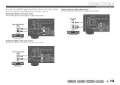
...COMPONENT VIDEO VIDEO C HDMI 3 HDMI 4 MONITOR OUT OPTICAL AV 1 COAXIAL COAXIAL (CD) OPTICAL ( TV ) AV 4 AV 5 AV OUT AUDIO 1 AUDIO 2 AUDIO OUT CD player We recommend connecting audio devices with an coaxial digital output to the AV input 3 just by pressing the "CD" SCENE key (☞p. 26... Y COMPONENT VIDEO VIDEO MONITOR OUT L OPTICAL AV 1 COAXIAL AV 2 COAXIAL (CD) AV 3 OPTICAL ( TV ) AV 4 R AV 5 AV OUT AUDIO 1 AUDIO 2 AUDIO OUT CD player Using optical digital output sources Select the AV input (AV1 or AV4) that the external device is connected to for playback.
...COMPONENT VIDEO VIDEO C HDMI 3 HDMI 4 MONITOR OUT OPTICAL AV 1 COAXIAL COAXIAL (CD) OPTICAL ( TV ) AV 4 AV 5 AV OUT AUDIO 1 AUDIO 2 AUDIO OUT CD player We recommend connecting audio devices with an coaxial digital output to the AV input 3 just by pressing the "CD" SCENE key (☞p. 26... Y COMPONENT VIDEO VIDEO MONITOR OUT L OPTICAL AV 1 COAXIAL AV 2 COAXIAL (CD) AV 3 OPTICAL ( TV ) AV 4 R AV 5 AV OUT AUDIO 1 AUDIO 2 AUDIO OUT CD player Using optical digital output sources Select the AV input (AV1 or AV4) that the external device is connected to for playback.

Owners Manual
Page 20
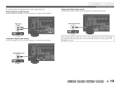
... COAXIAL (CD) AV 3 OPTICAL ( TV ) AV 4 AV 5 AV OUT AUDIO 1 AUDIO 2 AUDIO OUT VCR Audio input AUDIO L R Audio recorder Using the AV OUT jacks Connect this jacks to the external device's analog audio input jacks. Using the AUDIO OUT jacks Connect this unit and the other TVs or external devices. Select the V-... to VCRs or similar devices, or send them to use these jacks. AUDIO OUT RADIO STRAIGHT VIDEO AUX PORTABLE VIDEO L AUDIO R VL R Audio output L Audio output R V Video output AUDIO VIDEO Portable audio player Video cameras • Be sure to turn down the volume when ...
... COAXIAL (CD) AV 3 OPTICAL ( TV ) AV 4 AV 5 AV OUT AUDIO 1 AUDIO 2 AUDIO OUT VCR Audio input AUDIO L R Audio recorder Using the AV OUT jacks Connect this jacks to the external device's analog audio input jacks. Using the AUDIO OUT jacks Connect this unit and the other TVs or external devices. Select the V-... to VCRs or similar devices, or send them to use these jacks. AUDIO OUT RADIO STRAIGHT VIDEO AUX PORTABLE VIDEO L AUDIO R VL R Audio output L Audio output R V Video output AUDIO VIDEO Portable audio player Video cameras • Be sure to turn down the volume when ...
Owners Manual
Page 22
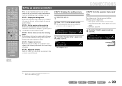
... the listening point at the appropriate timing. Subwoofer: connected 4 Check that "Speaker Setup" appears and press jENTER. SOURCE 1 1 5 TRANSMIT CODE SET SLEEP RECEIVER HDMI 2 3 4 AV 2 3 4 AUDIO 1 2 V-AUX [ A ] [ B ] DOCK TUNER FM AM PRESET TUNING INFO MEMORY MOVIE ENHANCER SUR. STEP 4: Playback a test tone Playback a test tone to allow you have finished connecting...
... the listening point at the appropriate timing. Subwoofer: connected 4 Check that "Speaker Setup" appears and press jENTER. SOURCE 1 1 5 TRANSMIT CODE SET SLEEP RECEIVER HDMI 2 3 4 AV 2 3 4 AUDIO 1 2 V-AUX [ A ] [ B ] DOCK TUNER FM AM PRESET TUNING INFO MEMORY MOVIE ENHANCER SUR. STEP 4: Playback a test tone Playback a test tone to allow you have finished connecting...
Owners Manual
Page 23
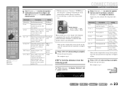
...Sur. L Surround speaker L 1.0 ft to 80.0 ft (0.30 m to 24.0 m) Sur. Choose "None" if you have surround speakers connected. None/Small/ Large Crossover Audio with a frequency below this limit will be output from the listening point 7 Press jCursor C to 200Hz SWFR Phase Switches the phase of the surround speakers... or not you want to configure, and press jCursor D / E to the previous menu. SOURCE 1 1 5 TRANSMIT CODE SET SLEEP RECEIVER HDMI 2 3 4 AV 2 3 4 AUDIO 1 2 V-AUX [ A ] [ B ] DOCK TUNER FM AM PRESET TUNING INFO MEMORY MOVIE ENHANCER SUR.
...Sur. L Surround speaker L 1.0 ft to 80.0 ft (0.30 m to 24.0 m) Sur. Choose "None" if you have surround speakers connected. None/Small/ Large Crossover Audio with a frequency below this limit will be output from the listening point 7 Press jCursor C to 200Hz SWFR Phase Switches the phase of the surround speakers... or not you want to configure, and press jCursor D / E to the previous menu. SOURCE 1 1 5 TRANSMIT CODE SET SLEEP RECEIVER HDMI 2 3 4 AV 2 3 4 AUDIO 1 2 V-AUX [ A ] [ B ] DOCK TUNER FM AM PRESET TUNING INFO MEMORY MOVIE ENHANCER SUR.
Owners Manual
Page 24
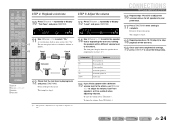
... speakers with a different volume level to the others , use in a clockwise fashion, as a default when adjusting volumes. SOURCE 1 1 5 TRANSMIT CODE SET SLEEP RECEIVER HDMI 2 3 4 AV 2 3 4 AUDIO 1 2 V-AUX [ A ] [ B ] DOCK TUNER FM AM PRESET TUNING INFO MEMORY MOVIE ENHANCER SUR.
... speakers with a different volume level to the others , use in a clockwise fashion, as a default when adjusting volumes. SOURCE 1 1 5 TRANSMIT CODE SET SLEEP RECEIVER HDMI 2 3 4 AV 2 3 4 AUDIO 1 2 V-AUX [ A ] [ B ] DOCK TUNER FM AM PRESET TUNING INFO MEMORY MOVIE ENHANCER SUR.

Owners Manual
Page 25
...En 25 J1 3 Play the external component that you release the key. PLAYBACK SOURCE 1 1 5 TRANSMIT CODE SET SLEEP RECEIVER HDMI 2 3 4 AV 2 3 4 AUDIO 1 2 V-AUX [ A ] [ B ] DOCK TUNER FM AM PRESET TUNING INFO MEMORY MOVIE ENHANCER SUR. Refer to select "Treble" or "Bass." Press sMUTE ...CH ENT d Input selector r VOLUME +/s MUTE Basic playback procedure 1 Turn on external components (TV, DVD d player, etc.) connected to mute the audio output. SW 0.0dB L C R SL SR 2 Press PROGRAM l / h to adjust the output level in those from the front left and right...
...En 25 J1 3 Play the external component that you release the key. PLAYBACK SOURCE 1 1 5 TRANSMIT CODE SET SLEEP RECEIVER HDMI 2 3 4 AV 2 3 4 AUDIO 1 2 V-AUX [ A ] [ B ] DOCK TUNER FM AM PRESET TUNING INFO MEMORY MOVIE ENHANCER SUR. Refer to select "Treble" or "Bass." Press sMUTE ...CH ENT d Input selector r VOLUME +/s MUTE Basic playback procedure 1 Turn on external components (TV, DVD d player, etc.) connected to mute the audio output. SW 0.0dB L C R SL SR 2 Press PROGRAM l / h to adjust the output level in those from the front left and right...


