Owner's Manual
Page 5
... codes 72 Resetting all remote control codes 72 Advanced setup 73 APPENDIX Troubleshooting 75 Glossary 88 Sound field program information 91 Information on HDMI 92 Specifications 93 Index 94 (at the end of this manual 3 Supplied accessories 3 Part names and functions 4 Front panel 4...zone configuration 69 Connecting Zone2/3 69 Controlling Zone2/3 71 Controlling other components 16 Connecting a Yamaha iPod universal dock or Bluetooth™ wireless audio receiver 18 Connecting to the network 19 Connecting a USB storage device 19 Using the VIDEO AUX jacks 19 Connecting the ...
... codes 72 Resetting all remote control codes 72 Advanced setup 73 APPENDIX Troubleshooting 75 Glossary 88 Sound field program information 91 Information on HDMI 92 Specifications 93 Index 94 (at the end of this manual 3 Supplied accessories 3 Part names and functions 4 Front panel 4...zone configuration 69 Connecting Zone2/3 69 Controlling Zone2/3 71 Controlling other components 16 Connecting a Yamaha iPod universal dock or Bluetooth™ wireless audio receiver 18 Connecting to the network 19 Connecting a USB storage device 19 Using the VIDEO AUX jacks 19 Connecting the ...
Owner's Manual
Page 6
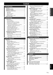
... function (Zone2/3) • DHCP automatic or manual network configuration • iTunes Tagging function (U.S.A. Deep Color video signal (30/36 bit) transmission - model only) ■ HDMI™ (High-Definition Multimedia Interface) • HDMI interface for the creation of sound fields • ...1) • Audio input (analog) x 2 • Phono input (analog) x 1 • Multi-channel audio input (7.1-channel) • DOCK terminal to connect a Yamaha iPod universal dock (such as YDS-11, sold separately) or Bluetooth wireless audio receiver (such as multi-channel digital audio. -
... function (Zone2/3) • DHCP automatic or manual network configuration • iTunes Tagging function (U.S.A. Deep Color video signal (30/36 bit) transmission - model only) ■ HDMI™ (High-Definition Multimedia Interface) • HDMI interface for the creation of sound fields • ...1) • Audio input (analog) x 2 • Phono input (analog) x 1 • Multi-channel audio input (7.1-channel) • DOCK terminal to connect a Yamaha iPod universal dock (such as YDS-11, sold separately) or Bluetooth wireless audio receiver (such as multi-channel digital audio. -
Owner's Manual
Page 7
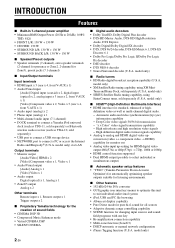
...icons) may be performed by Yamaha in Alaska and Hawaii. HD Radio™ Technology Manufactured Under License From iBiquity Digital Corp. This receiver supports network connections. Bluetooth™ Bluetooth is a trademark of the parts on the remote control. "HDMI", the "HDMI" logo and "High-Definition ... "SILENT CINEMA" is used in example screen images in this manual • Some operations can be different from that you received all related marks and logos are proprietary trademarks of Sirius XM Radio Inc. and other U.S. MPEG Layer-3 audio coding technology licensed...
...icons) may be performed by Yamaha in Alaska and Hawaii. HD Radio™ Technology Manufactured Under License From iBiquity Digital Corp. This receiver supports network connections. Bluetooth™ Bluetooth is a trademark of the parts on the remote control. "HDMI", the "HDMI" logo and "High-Definition ... "SILENT CINEMA" is used in example screen images in this manual • Some operations can be different from that you received all related marks and logos are proprietary trademarks of Sirius XM Radio Inc. and other U.S. MPEG Layer-3 audio coding technology licensed...
Owner's Manual
Page 8
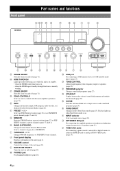
... TONE CONTROL Adjusts high-frequency/low-frequency output of speakers (page 21). Front panel Part names and functions A BC D E F GH IJ K HDMI THROUGH ZONE2 ON/OFF ZONE3 ON/OFF ZONE CONTROLS INFO l PRESET h MEMORY BAND CATEGORY l TUNING/CH h MAIN ZONE ON/OFF PHONES USB SILENT... CINEMA TONE CONTROL BD/DVD SCENE TV CD RADIO PROGRAM STRAIGHT PURE DIRECT INPUT EFFECT OPTIMIZER MIC VOLUME VIDEO AUX VIDEO AUDIO HDMI IN L MN O P QRS T U V A ZONE2 ON/OFF Switches Zone2 on and off (page 71). V VIDEO AUX jacks For connecting ...
... TONE CONTROL Adjusts high-frequency/low-frequency output of speakers (page 21). Front panel Part names and functions A BC D E F GH IJ K HDMI THROUGH ZONE2 ON/OFF ZONE3 ON/OFF ZONE CONTROLS INFO l PRESET h MEMORY BAND CATEGORY l TUNING/CH h MAIN ZONE ON/OFF PHONES USB SILENT... CINEMA TONE CONTROL BD/DVD SCENE TV CD RADIO PROGRAM STRAIGHT PURE DIRECT INPUT EFFECT OPTIMIZER MIC VOLUME VIDEO AUX VIDEO AUDIO HDMI IN L MN O P QRS T U V A ZONE2 ON/OFF Switches Zone2 on and off (page 71). V VIDEO AUX jacks For connecting ...
Owner's Manual
Page 9
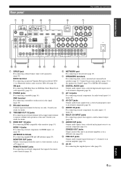
... j AV OUT jacks Outputs audio/visual signals from a selected digital audio input source to a video monitor, such as a TV (page 14). ADVANCED OPERATION ADDITIONAL INFORMATION APPENDIX English 5 En XM HDMI OUT 1 HDMI OUT 2 (HDMI CONTROL) HDMI 1 (BD/DVD) HDMI 2 HDMI 3 HDMI 4 NETWORK DOCK COMPONENT... audio/visual inputs 1-6 (page 16). DOCK terminal For connecting an optional Yamaha iPod universal dock (YDS11) or Bluetooth wireless audio receiver (YBA-10) (page 18). m n o f NETWORK port For connecting to an external amplifier (page 18). INTRODUCTION PREPARATION BASIC OPERATION...
... j AV OUT jacks Outputs audio/visual signals from a selected digital audio input source to a video monitor, such as a TV (page 14). ADVANCED OPERATION ADDITIONAL INFORMATION APPENDIX English 5 En XM HDMI OUT 1 HDMI OUT 2 (HDMI CONTROL) HDMI 1 (BD/DVD) HDMI 2 HDMI 3 HDMI 4 NETWORK DOCK COMPONENT... audio/visual inputs 1-6 (page 16). DOCK terminal For connecting an optional Yamaha iPod universal dock (YDS11) or Bluetooth wireless audio receiver (YBA-10) (page 18). m n o f NETWORK port For connecting to an external amplifier (page 18). INTRODUCTION PREPARATION BASIC OPERATION...
Owner's Manual
Page 10
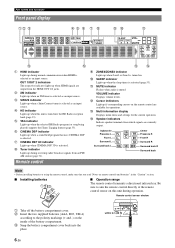
...on the inside of the battery compartment. k MUTE indicator Flashes when audio is selected. l Cursor indicators Light up during normal communication when HDMI is selected as an input source. f CINEMA DSP indicator Lights up when a SiriusConnect tuner is selected as an input source. n ...3 TUNED SLEEP VOL. ZONE ZONE 2 3 MUTE PL SW PR L CR SL SR SBL SB SBR l m a HDMI indicator Lights up when an XM tuner is selected as an input source. b XM indicator Lights up during receiving radio broadcast signals from which signals are available for the current operation.
...on the inside of the battery compartment. k MUTE indicator Flashes when audio is selected. l Cursor indicators Light up during normal communication when HDMI is selected as an input source. f CINEMA DSP indicator Lights up when a SiriusConnect tuner is selected as an input source. n ...3 TUNED SLEEP VOL. ZONE ZONE 2 3 MUTE PL SW PR L CR SL SR SBL SB SBR l m a HDMI indicator Lights up when an XM tuner is selected as an input source. b XM indicator Lights up during receiving radio broadcast signals from which signals are available for the current operation.
Owner's Manual
Page 11
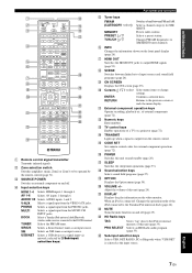
DOCK Selects a Yamaha iPod universal dock/Bluetooth wireless audio receiver connected to the iPod or internal memory...panel display (page 26). AV 1-6 Selects AV inputs 1 through 4. AUDIO 1/2 Selects AUDIO inputs 1 and 2. SIRIUS Selects a SiriusConnect tuner as an input source. USB/NET Selects a USB device or a signal input via network (selected by the remote...(main, Zone2 or Zone3) to the previous screen or ends the menu display. g HDMI OUT Switches the HDMI OUT jacks to the Yamaha iPod universal dock (page 44). r Sound selection keys Selects sound field programs (page...
DOCK Selects a Yamaha iPod universal dock/Bluetooth wireless audio receiver connected to the iPod or internal memory...panel display (page 26). AV 1-6 Selects AV inputs 1 through 4. AUDIO 1/2 Selects AUDIO inputs 1 and 2. SIRIUS Selects a SiriusConnect tuner as an input source. USB/NET Selects a USB device or a signal input via network (selected by the remote...(main, Zone2 or Zone3) to the previous screen or ends the menu display. g HDMI OUT Switches the HDMI OUT jacks to the Yamaha iPod universal dock (page 44). r Sound selection keys Selects sound field programs (page...
Owner's Manual
Page 13
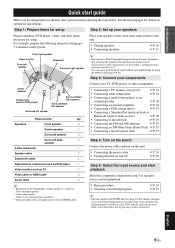
...;P. 18 • Connecting a USB storage device ☞P. 19 • Connecting a Yamaha iPod universal dock or Bluetooth wireless audio receiver ☞P. 18 • Connecting to this unit. • Placing speakers • ... source and start playback Select the component connected in the room and connect them to the network ☞P. 19 • Connecting the FM and AM antennas ☞P. 20 •...Prepare speakers, DVD player, cables, and other speakers is as TV 1 Video cable or HDMI cable 2 Audio cable 2 y • The priority of the requirement of the speakers...
...;P. 18 • Connecting a USB storage device ☞P. 19 • Connecting a Yamaha iPod universal dock or Bluetooth wireless audio receiver ☞P. 18 • Connecting to this unit. • Placing speakers • ... source and start playback Select the component connected in the room and connect them to the network ☞P. 19 • Connecting the FM and AM antennas ☞P. 20 •...Prepare speakers, DVD player, cables, and other speakers is as TV 1 Video cable or HDMI cable 2 Audio cable 2 y • The priority of the requirement of the speakers...
Owner's Manual
Page 15
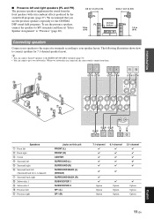
... can connect Zone2/3 speakers to the EXTRA SP (SP1/SP2) terminals (page 70). • You can connect up to two subwoofers. k j b a c id e h g f ba ed kj 3 HDMI 4 NETWORK SPEAKERS E SP1 EXTRA SP ZONE2/PRESENCE SINGLE CLASS 2 WIRING FRONT CENTER CENTER SURROUND SINGLE SURROUND BACK/ BI-AMP CENTER Speakers a Front left b Front right c Center...
... can connect Zone2/3 speakers to the EXTRA SP (SP1/SP2) terminals (page 70). • You can connect up to two subwoofers. k j b a c id e h g f ba ed kj 3 HDMI 4 NETWORK SPEAKERS E SP1 EXTRA SP ZONE2/PRESENCE SINGLE CLASS 2 WIRING FRONT CENTER CENTER SURROUND SINGLE SURROUND BACK/ BI-AMP CENTER Speakers a Front left b Front right c Center...

Owner's Manual
Page 17
... ↔ DVI-D jack) to connect this unit to other DVI components. • You can check the potential problem about the HDMI connection (page 55). Use pin cables. OPTICAL jacks O OPTICAL To transmit optical digital audio signals. R (red) COAXIAL jacks (orange) C COAXIAL ... 13 En Use jacks and cables appropriate for components that include luminance (Y), chrominance blue (PB) and chrominance red (PR) components. HDMI jacks HDMI HDMI To transmit digital video and digital audio signals. To transmit component video signals that you use a commercially available 19-pin...
... ↔ DVI-D jack) to connect this unit to other DVI components. • You can check the potential problem about the HDMI connection (page 55). Use pin cables. OPTICAL jacks O OPTICAL To transmit optical digital audio signals. R (red) COAXIAL jacks (orange) C COAXIAL ... 13 En Use jacks and cables appropriate for components that include luminance (Y), chrominance blue (PB) and chrominance red (PR) components. HDMI jacks HDMI HDMI To transmit digital video and digital audio signals. To transmit component video signals that you use a commercially available 19-pin...

Owner's Manual
Page 18
...PB VIDEO b Projector Jacks on components a HDMI input b HDMI input Jacks on this unit HDMI OUT 1 HDMI OUT 2 y • This unit is equipped with the remote control of your TV. XM HDMI OUT 1 HDMI OUT 2 HDMI 1 (BD/DVD) HDMI 2 HDMI 3 HD Radio VIDEO MONITOR OUT COMPONENT ... OUT (page 53). • This unit supports the HDMI control function (page 53). XM HDMI OUT 1 HDMI OUT 2 (HDMI CONTROL) HDMI 1 (BD/DVD) HDMI 2 HDMI 3 HD Radio UNBAL. VIDEO TRIGGER OUT 1 2 12V 0.1A MAX. HDMI OUT 2 HDMI 1 (BD/DVD) HDMI 2 HDMI 3 OR OUT COMPONENT VIDEO PR REMOTE IN OUT PB VIDEO...
...PB VIDEO b Projector Jacks on components a HDMI input b HDMI input Jacks on this unit HDMI OUT 1 HDMI OUT 2 y • This unit is equipped with the remote control of your TV. XM HDMI OUT 1 HDMI OUT 2 HDMI 1 (BD/DVD) HDMI 2 HDMI 3 HD Radio VIDEO MONITOR OUT COMPONENT ... OUT (page 53). • This unit supports the HDMI control function (page 53). XM HDMI OUT 1 HDMI OUT 2 (HDMI CONTROL) HDMI 1 (BD/DVD) HDMI 2 HDMI 3 HD Radio UNBAL. VIDEO TRIGGER OUT 1 2 12V 0.1A MAX. HDMI OUT 2 HDMI 1 (BD/DVD) HDMI 2 HDMI 3 OR OUT COMPONENT VIDEO PR REMOTE IN OUT PB VIDEO...
Owner's Manual
Page 20
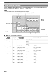
...input (PHONO) Audio / video output (AV OUT) Audio output (DIGITAL AUDIO) GND terminal Audio / video input (AV 1-6) PHONO RS- 232C TRIGGER OUT 1 2 12V 0.1A MAX. SIRIUS XM HDMI OUT 1 HDMI OUT 2 (HDMI CONTROL) HDMI 1 (BD/DVD) HDMI 2 HDMI 3 HDMI 4 DOCK COMPONENT OUT VIDEO PR OPTICAL ...VIDEO MONITOR OUT COMPONENT VIDEO PR REMOTE IN OUT PB VIDEO Y FRONT CENTER HDMI input (HDMI 1-4) Audio output (AUDIO OUT) OPTICAL ( TV ) AV 1 COAXIAL AV 2 COAXIAL (CD) AV 3 OPTICAL AV 4 AV 5 AV 6 AV OUT AUDIO1 AUDIO2 FRONT SURROUND SUR.BACK SUBWOOFER MULTI CH INPUT AUDIO OUT ...
...input (PHONO) Audio / video output (AV OUT) Audio output (DIGITAL AUDIO) GND terminal Audio / video input (AV 1-6) PHONO RS- 232C TRIGGER OUT 1 2 12V 0.1A MAX. SIRIUS XM HDMI OUT 1 HDMI OUT 2 (HDMI CONTROL) HDMI 1 (BD/DVD) HDMI 2 HDMI 3 HDMI 4 DOCK COMPONENT OUT VIDEO PR OPTICAL ...VIDEO MONITOR OUT COMPONENT VIDEO PR REMOTE IN OUT PB VIDEO Y FRONT CENTER HDMI input (HDMI 1-4) Audio output (AUDIO OUT) OPTICAL ( TV ) AV 1 COAXIAL AV 2 COAXIAL (CD) AV 3 OPTICAL AV 4 AV 5 AV 6 AV OUT AUDIO1 AUDIO2 FRONT SURROUND SUR.BACK SUBWOOFER MULTI CH INPUT AUDIO OUT ...
Owner's Manual
Page 21
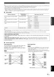
...OPERATION ADDITIONAL INFORMATION APPENDIX English 17 En About audio/video output jacks When using the AV OUT jacks: connect these jacks to the AV3 jack of an external component. HDMI Input HDMI Output HDMI OUT PR Component video PB Y Composite VIDEO video PR PB Y VIDEO Audio ...making a video connection (component video or composite). In this case, you connect an external component with analog audio output Analog audio output AV 5 AV 6 Analog audio Analog audio AUDIO 1 Analog audio AUDIO 2 Analog audio Turntable Analog audio output PHONO Analog audio y • If ...
...OPERATION ADDITIONAL INFORMATION APPENDIX English 17 En About audio/video output jacks When using the AV OUT jacks: connect these jacks to the AV3 jack of an external component. HDMI Input HDMI Output HDMI OUT PR Component video PB Y Composite VIDEO video PR PB Y VIDEO Audio ...making a video connection (component video or composite). In this case, you connect an external component with analog audio output Analog audio output AV 5 AV 6 Analog audio Analog audio AUDIO 1 Analog audio AUDIO 2 Analog audio Turntable Analog audio output PHONO Analog audio y • If ...
Owner's Manual
Page 22
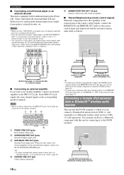
...from a multiformat player, external decoder, etc. Infrared signal receiver or Yamaha component IR flasher or Yamaha component (CD or DVD player, etc.) y • If connecting a Yamaha component that supports the SCENE control signal reception to the ...HDMI 2 HDMI 3 HDMI 4 MONITOR OUT COMPONENT VIDEO PR REMOTE IN OUT PB VIDEO Y Remote control out Remote control in the advanced setup menu (page 73). b SURROUND PRE OUT jacks Surround channel output jacks. a bc d SINGLE CENTER FRONT SURROUND SUR. Connecting a Yamaha iPod universal dock or Bluetooth™ wireless audio receiver...
...from a multiformat player, external decoder, etc. Infrared signal receiver or Yamaha component IR flasher or Yamaha component (CD or DVD player, etc.) y • If connecting a Yamaha component that supports the SCENE control signal reception to the ...HDMI 2 HDMI 3 HDMI 4 MONITOR OUT COMPONENT VIDEO PR REMOTE IN OUT PB VIDEO Y Remote control out Remote control in the advanced setup menu (page 73). b SURROUND PRE OUT jacks Surround channel output jacks. a bc d SINGLE CENTER FRONT SURROUND SUR. Connecting a Yamaha iPod universal dock or Bluetooth™ wireless audio receiver...
Owner's Manual
Page 23
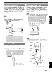
...cover to the VIDEO AUX jacks when you need to configure the network settings manually (page 64). ORY CABTEAGNODRY l TUNING/CH h VOLUME INPUT OPTIMIZER MIC VIDEO AUX VIDEO AUDIO HDMI IN PUSH Atlach the cover USB USB memory device or USB ... DIRECT INPUT EFFECT OPTIMIZER MIC VIDEO AUX VIDEO AUDIO HDMI IN VIDEO L AUDIO R HDMI IN LAN PC Modem V L R HDMI HDMI output Analog audio output Video output Router Network cable TRIGGER OUT 1 2 12V 0.1A MAX. 2 HDMI 1 (BD/DVD) HDMI 2 HDMI 3 HDMI 4 NETWORK MONITOR OUT COMPONENT REMOTE IN Connecting a USB storage ...
...cover to the VIDEO AUX jacks when you need to configure the network settings manually (page 64). ORY CABTEAGNODRY l TUNING/CH h VOLUME INPUT OPTIMIZER MIC VIDEO AUX VIDEO AUDIO HDMI IN PUSH Atlach the cover USB USB memory device or USB ... DIRECT INPUT EFFECT OPTIMIZER MIC VIDEO AUX VIDEO AUDIO HDMI IN VIDEO L AUDIO R HDMI IN LAN PC Modem V L R HDMI HDMI output Analog audio output Video output Router Network cable TRIGGER OUT 1 2 12V 0.1A MAX. 2 HDMI 1 (BD/DVD) HDMI 2 HDMI 3 HDMI 4 NETWORK MONITOR OUT COMPONENT REMOTE IN Connecting a USB storage ...

Owner's Manual
Page 24
...Indoor FM antenna AM loop antenna Connecting the power cable After all connections are complete, plug the supplied power cable into an AC wall outlet. (HDMI CONTROL) (BD/DVD) DOCK COMPONENT OUT VIDEO PR OPTICAL DIGITAL AUDIO GND PB Y ANTENNA HD Radio FM GND AM UNBAL. y • The... this unit (standby mode). We recommend disconnecting the power cable from this unit to the GND terminal. For details, consult the nearest authorized Yamaha dealer or service center. • Always use an outdoor antenna. Turning this unit on and off 1 Press LMAIN ZONE ON/OFF on...
...Indoor FM antenna AM loop antenna Connecting the power cable After all connections are complete, plug the supplied power cable into an AC wall outlet. (HDMI CONTROL) (BD/DVD) DOCK COMPONENT OUT VIDEO PR OPTICAL DIGITAL AUDIO GND PB Y ANTENNA HD Radio FM GND AM UNBAL. y • The... this unit (standby mode). We recommend disconnecting the power cable from this unit to the GND terminal. For details, consult the nearest authorized Yamaha dealer or service center. • Always use an outdoor antenna. Turning this unit on and off 1 Press LMAIN ZONE ON/OFF on...
Owner's Manual
Page 25
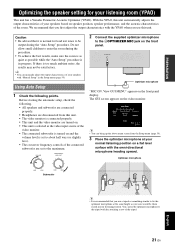
...disconnected from the Setup menu (page 59). 3 Place the optimizer microphone at the same height as your listening room (YPAO) This unit has a Yamaha Parametric Acoustic Optimizer (YPAO). Do not allow small children to enter the room during the "Auto Setup" procedure. y • You can fix... similar to fix the optimizer microphone at your speakers with the omni-directional microphone heading upward. INPUT OPTIMIZER MIC VIDEO AUX VIDEO AUDIO HDMI IN Optimizer microphone "MIC ON. The GUI screen appears on the front panel. With the YPAO, this unit. • The ...
...disconnected from the Setup menu (page 59). 3 Place the optimizer microphone at the same height as your listening room (YPAO) This unit has a Yamaha Parametric Acoustic Optimizer (YPAO). Do not allow small children to enter the room during the "Auto Setup" procedure. y • You can fix... similar to fix the optimizer microphone at your speakers with the omni-directional microphone heading upward. INPUT OPTIMIZER MIC VIDEO AUX VIDEO AUDIO HDMI IN Optimizer microphone "MIC ON. The GUI screen appears on the front panel. With the YPAO, this unit. • The ...
Owner's Manual
Page 28
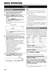
...as playing movies or music. Keys Input source Sound field program BD/DVD HDMI 1 Straight TV AV 1 Straight CD AV 3 Straight RADIO TUNER 7ch Enhancer y • When this unit is displayed...in some conditions, which may results from the playback component. y • If you connect a Yamaha DVD/CD player that you can change the input source name displayed on the front panel display or... factory settings. If you connect two video monitors to the HDMI OUT jacks of an iPod, Bluetooth component, USB storage device or network contents using the SCENE function. Volume -18.5dB SW L...
...as playing movies or music. Keys Input source Sound field program BD/DVD HDMI 1 Straight TV AV 1 Straight CD AV 3 Straight RADIO TUNER 7ch Enhancer y • When this unit is displayed...in some conditions, which may results from the playback component. y • If you connect a Yamaha DVD/CD player that you can change the input source name displayed on the front panel display or... factory settings. If you connect two video monitors to the HDMI OUT jacks of an iPod, Bluetooth component, USB storage device or network contents using the SCENE function. Volume -18.5dB SW L...
Owner's Manual
Page 39
... copy, decompile, disassemble, reverse engineer, hack, manipulate or otherwise make available any technology or software incorporated in receivers compatible with no obstacles in the following eight squares for reference. PHONO RS SIRIUS XM HDMI OUT (HDMI CONTROL) DOCK COMPONENT OUT VIDEO ANTENNA HD Radio FM Note • If "CHECK ANTENNA", "CHECK XM TUNER...
... copy, decompile, disassemble, reverse engineer, hack, manipulate or otherwise make available any technology or software incorporated in receivers compatible with no obstacles in the following eight squares for reference. PHONO RS SIRIUS XM HDMI OUT (HDMI CONTROL) DOCK COMPONENT OUT VIDEO ANTENNA HD Radio FM Note • If "CHECK ANTENNA", "CHECK XM TUNER...
Owner's Manual
Page 57
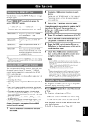
...Steps 4 through 6 are required for making the TV learn linked devices. y • This unit automatically activates the HDMI OUT 1 jack when receiving an HDMI control signal through 3 are required for the HDMI control function setup.) 1 Turn on each device. • We suggest that you select this unit or TV) y... function supported) is not selected. For details, refer to the manual supplied with HDMI. 2 Enable the HDMI control function on all devices connected to this unit is connected to the AV 1 (OPTICAL) jack of this unit. • Turning on the TV. If the connections or ...
...Steps 4 through 6 are required for making the TV learn linked devices. y • This unit automatically activates the HDMI OUT 1 jack when receiving an HDMI control signal through 3 are required for the HDMI control function setup.) 1 Turn on each device. • We suggest that you select this unit or TV) y... function supported) is not selected. For details, refer to the manual supplied with HDMI. 2 Enable the HDMI control function on all devices connected to this unit is connected to the AV 1 (OPTICAL) jack of this unit. • Turning on the TV. If the connections or ...


