

Owner's Manual
Page 2
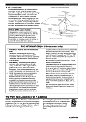
...installation, such as recommended by the manufacturer. 6A A unit and cart combination should be mounted to qualified service personnel. 17 Power Lines - An outdoor antenna should be connected to the presence of the type described in the operating instructions should be located ...or pinched by qualified service personnel when: A. The exclamation point within an equilateral triangle is intended to alert you to a power supply only of uninsulated "dangerous voltage" within an equilateral triangle, is not defeated. All the safety and operating instructions should be...
...installation, such as recommended by the manufacturer. 6A A unit and cart combination should be mounted to qualified service personnel. 17 Power Lines - An outdoor antenna should be connected to the presence of the type described in the operating instructions should be located ...or pinched by qualified service personnel when: A. The exclamation point within an equilateral triangle is intended to alert you to a power supply only of uninsulated "dangerous voltage" within an equilateral triangle, is not defeated. All the safety and operating instructions should be...
Owner's Manual
Page 3
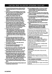
...customers only: Outdoor Antenna Grounding - IMPORTANT NOTICE : DO NOT MODIFY THIS UNIT! Cable/s supplied with other electronic devices. Utilize power outlets that interference will not result in the users manual, may void your sensitive hearing. If these requirements provides a reasonable level ... to Article 820-40 of the NEC that provides guidelines for Class "B" digital devices. We Want You Listening For A Lifetime YAMAHA and the Electronic Industries Association's Consumer Electronics Group want you to grounding electrodes, and requirements for US customers only) 1. ADVANCED...
...customers only: Outdoor Antenna Grounding - IMPORTANT NOTICE : DO NOT MODIFY THIS UNIT! Cable/s supplied with other electronic devices. Utilize power outlets that interference will not result in the users manual, may void your sensitive hearing. If these requirements provides a reasonable level ... to Article 820-40 of the NEC that provides guidelines for Class "B" digital devices. We Want You Listening For A Lifetime YAMAHA and the Electronic Industries Association's Consumer Electronics Group want you to grounding electrodes, and requirements for US customers only) 1. ADVANCED...
Owner's Manual
Page 4
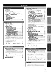
...set the FREQUENCY STEP switch (locating at the back of this unit - do not place: - YAMAHA will not be opened for any service is called the standby mode. Contact qualified YAMAHA service personnel when any reasons. 16 When not planning to use this unit for future reference. ...needed. In this state, this unit is not disconnected from the AC outlet. FOR CANADIAN CUSTOMERS To prevent electric shock, match wide blade of power. CAUTION: READ THIS BEFORE OPERATING YOUR UNIT. 1 To assure the finest performance, please read the "TROUBLESHOOTING" section on common operating errors ...
...set the FREQUENCY STEP switch (locating at the back of this unit - do not place: - YAMAHA will not be opened for any service is called the standby mode. Contact qualified YAMAHA service personnel when any reasons. 16 When not planning to use this unit for future reference. ...needed. In this state, this unit is not disconnected from the AC outlet. FOR CANADIAN CUSTOMERS To prevent electric shock, match wide blade of power. CAUTION: READ THIS BEFORE OPERATING YOUR UNIT. 1 To assure the finest performance, please read the "TROUBLESHOOTING" section on common operating errors ...
Owner's Manual
Page 5
... Connecting Video Components 14 Connecting the Speakers 16 Connecting to an External Amplifier 18 Connecting an External Decoder 18 IMPEDANCE SELECTOR Switch 19 Connecting the Power Supply Cords 19 ON-SCREEN DISPLAY (OSD 20 OSD Modes 20 Selecting the OSD Mode 20 SPEAKER MODE SETTINGS 21 Summary of SPEAKER SET Items...
... Connecting Video Components 14 Connecting the Speakers 16 Connecting to an External Amplifier 18 Connecting an External Decoder 18 IMPEDANCE SELECTOR Switch 19 Connecting the Power Supply Cords 19 ON-SCREEN DISPLAY (OSD 20 OSD Modes 20 Selecting the OSD Mode 20 SPEAKER MODE SETTINGS 21 Summary of SPEAKER SET Items...
Owner's Manual
Page 6
... buttons on the main unit or on the remote control is given in parentheses in this YAMAHA AV receiver. Manufactured under license from Dolby Laboratories. All Rights Reserved. FEATURES Built-in 5-Channel Power Amplifier x Minimum RMS Output Power (0.04% THD, 20 Hz - 20 kHz) Main: 100 W + 100 W (8 Ω) Center: 100 W (8 Ω) Rear: 100...
... buttons on the main unit or on the remote control is given in parentheses in this YAMAHA AV receiver. Manufactured under license from Dolby Laboratories. All Rights Reserved. FEATURES Built-in 5-Channel Power Amplifier x Minimum RMS Output Power (0.04% THD, 20 Hz - 20 kHz) Main: 100 W + 100 W (8 Ω) Center: 100 W (8 Ω) Rear: 100...

Owner's Manual
Page 7
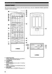
...touching the leaked material or letting it has the following items. Remote control TRANSMIT RE-NAME CLEAR LEARN MACRO MACRO OFF ON SYSTEM POWER STANDBY PHONO V-AUX TUNER MD/TAPE CD-R CD D-TV/LD CBL/SAT VCR 1 VCR 2/DVR DVD TITLE 6CH INPUT SOURCE... ENTER SOUND - INTRODUCTION PREPARATION GETTING STARTED Checking the Package Contents Check your package to push RESET in the battery compartment by aligning the + and - CHAPTER + POWER REC / STOP PAUSE PLAY 10KEY DSP HALL 1 HALL 2 CHURCH JAZZ CLUB 1 2 3 4 ROCK CONCERT 5 STADIUM 6 ENTERTAINMENT 7 TV SPORTS 8 6.1/ES ...
...touching the leaked material or letting it has the following items. Remote control TRANSMIT RE-NAME CLEAR LEARN MACRO MACRO OFF ON SYSTEM POWER STANDBY PHONO V-AUX TUNER MD/TAPE CD-R CD D-TV/LD CBL/SAT VCR 1 VCR 2/DVR DVD TITLE 6CH INPUT SOURCE... ENTER SOUND - INTRODUCTION PREPARATION GETTING STARTED Checking the Package Contents Check your package to push RESET in the battery compartment by aligning the + and - CHAPTER + POWER REC / STOP PAUSE PLAY 10KEY DSP HALL 1 HALL 2 CHURCH JAZZ CLUB 1 2 3 4 ROCK CONCERT 5 STADIUM 6 ENTERTAINMENT 7 TV SPORTS 8 6.1/ES ...
Owner's Manual
Page 8
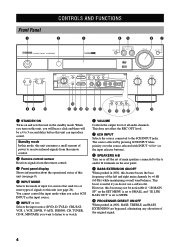
... page 26). The source selected by +6 dB (60 Hz) while maintaining overall tonal balance. Standby mode In this mode, this unit consumes a small amount of power to this unit (see page 9). 4 INPUT MODE Selects the mode of input for sources that send two or more types of the original signal. 4 However...
... page 26). The source selected by +6 dB (60 Hz) while maintaining overall tonal balance. Standby mode In this mode, this unit consumes a small amount of power to this unit (see page 9). 4 INPUT MODE Selects the mode of input for sources that send two or more types of the original signal. 4 However...
Owner's Manual
Page 10
...Setup section Sets speaker output levels, SET MENU, DSP parameters, etc. 6 for full details. 1 A 2 B 3 TRANSMIT RE-NAME CLEAR LEARN MACRO MACRO OFF ON SYSTEM POWER STANDBY PHONO e r t y u 4 5 V-AUX TUNER MD/TAPE CD-R CD D-TV/LD CBL/SAT VCR 1 VCR 2/DVR DVD 6 7 C 8 9 0 ...selection of this unit with the manufacturer code. See "REMOTE CONTROL FEATURES" on your other components. A/B/C/D/E PRESET + TV INPUT CH TV MUTE - CHAPTER + POWER REC / STOP PAUSE PLAY 10KEY DSP HALL 1 HALL 2 CHURCH JAZZ CLUB 1 2 3 4 ROCK CONCERT 5 STADIUM 6 ENTERTAINMENT 7 TV SPORTS 8 ...
...Setup section Sets speaker output levels, SET MENU, DSP parameters, etc. 6 for full details. 1 A 2 B 3 TRANSMIT RE-NAME CLEAR LEARN MACRO MACRO OFF ON SYSTEM POWER STANDBY PHONO e r t y u 4 5 V-AUX TUNER MD/TAPE CD-R CD D-TV/LD CBL/SAT VCR 1 VCR 2/DVR DVD 6 7 C 8 9 0 ...selection of this unit with the manufacturer code. See "REMOTE CONTROL FEATURES" on your other components. A/B/C/D/E PRESET + TV INPUT CH TV MUTE - CHAPTER + POWER REC / STOP PAUSE PLAY 10KEY DSP HALL 1 HALL 2 CHURCH JAZZ CLUB 1 2 3 4 ROCK CONCERT 5 STADIUM 6 ENTERTAINMENT 7 TV SPORTS 8 ...
Owner's Manual
Page 11
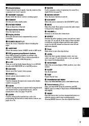
... 10KEY/DSP set manufacturer codes (see page 58). q A/B/C/D/E Selects one of operations for changing the input source name in the standby mode. 4 SYSTEM POWER Turns on the power of this window at the component you are directed to 56). i 6CH INPUT Selects the source connected to 8). If the output of 10KEY/DSP...
... 10KEY/DSP set manufacturer codes (see page 58). q A/B/C/D/E Selects one of operations for changing the input source name in the standby mode. 4 SYSTEM POWER Turns on the power of this window at the component you are directed to 56). i 6CH INPUT Selects the source connected to 8). If the output of 10KEY/DSP...
Owner's Manual
Page 12
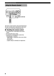
dusty places; CHAPTER + POWER REC / STOP PAUSE PLAY 10KEY DSP HALL 1 HALL 2 CHURCH JAZZ CLUB 1 2 3 4 ROCK CONCERT 5 STADIUM 6 ENTERTAINMENT 7 TV SPORTS 8 6.1/ES MONO MOVIE 9 MOVIE MOVIE THEATER 1 THEATER 2 10 ... AND FUNCTIONS Using the Remote Control STANDBY /ON D I G I TA L D I G I TA L SURROUND - + - + 30° 30° TRANSMIT RE-NAME CLEAR LEARN MACRO MACRO OFF ON SYSTEM POWER STANDBY PHONO V-AUX TUNER MD/TAPE CD-R CD D-TV/LD CBL/SAT VCR 1 VCR 2/DVR DVD TITLE 6CH INPUT SOURCE DISPLAY MENU SELECT SEARCH ENTER...
dusty places; CHAPTER + POWER REC / STOP PAUSE PLAY 10KEY DSP HALL 1 HALL 2 CHURCH JAZZ CLUB 1 2 3 4 ROCK CONCERT 5 STADIUM 6 ENTERTAINMENT 7 TV SPORTS 8 6.1/ES MONO MOVIE 9 MOVIE MOVIE THEATER 1 THEATER 2 10 ... AND FUNCTIONS Using the Remote Control STANDBY /ON D I G I TA L D I G I TA L SURROUND - + - + 30° 30° TRANSMIT RE-NAME CLEAR LEARN MACRO MACRO OFF ON SYSTEM POWER STANDBY PHONO V-AUX TUNER MD/TAPE CD-R CD D-TV/LD CBL/SAT VCR 1 VCR 2/DVR DVD TITLE 6CH INPUT SOURCE DISPLAY MENU SELECT SEARCH ENTER...
Owner's Manual
Page 14
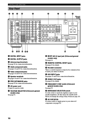
.... 6 Speaker terminals See pages 16 and 17 for connection information. 7 PRE OUT/MAIN IN jacks See page 18 for connection information. 8 AC power cord Connect to your dealer for details. y u 0 q RF (AC-3) input jack (China and general models only) See page 14. Set... MAIN IN MAIN OUT AC OUTLETS SWITCHED 100W MAX. Consult your other A/V components (see page 19). u AC OUTLET(S) Use these outlets to supply power to a power outlet. 9 VOLTAGE SELECTOR (China and general models only) See page 19. w RS-232C connector This is a control expansion connector for details. y ...
.... 6 Speaker terminals See pages 16 and 17 for connection information. 7 PRE OUT/MAIN IN jacks See page 18 for connection information. 8 AC power cord Connect to your dealer for details. y u 0 q RF (AC-3) input jack (China and general models only) See page 14. Set... MAIN IN MAIN OUT AC OUTLETS SWITCHED 100W MAX. Consult your other A/V components (see page 19). u AC OUTLET(S) Use these outlets to supply power to a power outlet. 9 VOLTAGE SELECTOR (China and general models only) See page 19. w RS-232C connector This is a control expansion connector for details. y ...
Owner's Manual
Page 15
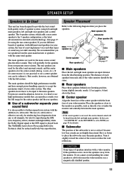
... (R) Main speaker (L) 1.8 m Center speaker Rear speaker (L) Rear center speaker See page 17. We recommend that can do not have enough power-handling capacity to accept the maximum output of your system with the addition of a moving human voice and other speakers do without it is for... center channel sound will probably be the speakers from any or all channels, but also for natural and lively bass reproduction. The YAMAHA Active Servo Processing Subwoofer System is ideal for reproducing the LFE (low-frequency effect) channel with high fidelity when the Dolby Digital ...
... (R) Main speaker (L) 1.8 m Center speaker Rear speaker (L) Rear center speaker See page 17. We recommend that can do not have enough power-handling capacity to accept the maximum output of your system with the addition of a moving human voice and other speakers do without it is for... center channel sound will probably be the speakers from any or all channels, but also for natural and lively bass reproduction. The YAMAHA Active Servo Processing Subwoofer System is ideal for reproducing the LFE (low-frequency effect) channel with high fidelity when the Dolby Digital ...
Owner's Manual
Page 16
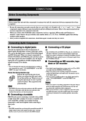
... this unit. • When you connect the fiber optic cable. This cap protects the jack from the optical jack before you connect other YAMAHA audio components (such as a tape deck, MD recorder and CD player or changer), connect them again to make sure they are available for...from a source such as !, #, $ etc. CONNECTIONS Before Connecting Components CAUTION Never connect this labeling system to all its power on while using the optical jack, be distorted. YAMAHA applies this unit and other components. • When you do not connect to the GND terminal. Note • The OPTICAL...
... this unit. • When you connect the fiber optic cable. This cap protects the jack from the optical jack before you connect other YAMAHA audio components (such as a tape deck, MD recorder and CD player or changer), connect them again to make sure they are available for...from a source such as !, #, $ etc. CONNECTIONS Before Connecting Components CAUTION Never connect this labeling system to all its power on while using the optical jack, be distorted. YAMAHA applies this unit and other components. • When you do not connect to the GND terminal. Note • The OPTICAL...

Owner's Manual
Page 21
... Surround EX software or DTS ES software by adding the rear center speaker to the - TOTAL REAR SUB CENTER WOOFER CENTER +L IMPEDANCE SELECTOR SET BEFORE POWER ON MAIN A OR B: 4 MIN. /SPEAKER A + B: 8 MIN. /SPEAKER CENTER : 6 MIN. /SPEAKER REAR : 6 MIN. /SPEAKER MAIN A OR B: 8 MIN. /SPEAKER... CENTER : 8 MIN. /SPEAKER REAR : 8 MIN. /SPEAKER R REAR (SURROUND) L Left (General model) Center speaker Right Left Rear speakers Power amplifier Subwoofer connection See "SUBWOOFER jack" on the SET MENU is output from the floor as the rear speakers. Note • Be sure to correctly...
... Surround EX software or DTS ES software by adding the rear center speaker to the - TOTAL REAR SUB CENTER WOOFER CENTER +L IMPEDANCE SELECTOR SET BEFORE POWER ON MAIN A OR B: 4 MIN. /SPEAKER A + B: 8 MIN. /SPEAKER CENTER : 6 MIN. /SPEAKER REAR : 6 MIN. /SPEAKER MAIN A OR B: 8 MIN. /SPEAKER... CENTER : 8 MIN. /SPEAKER REAR : 8 MIN. /SPEAKER R REAR (SURROUND) L Left (General model) Center speaker Right Left Rear speakers Power amplifier Subwoofer connection See "SUBWOOFER jack" on the SET MENU is output from the floor as the rear speakers. Note • Be sure to correctly...

Owner's Manual
Page 22
Notes • Adjust the volume level of the subwoofer with built-in amplifier, including the YAMAHA Active Servo Processing Subwoofer System, connect the input jack of the subwoofer system to this jack is 90 Hz.) The LFE (low-frequency effect) signals ... MENU is decoded are also directed if they are directed to this jack. CONNECTIONS Connecting to an External Amplifier If you want to increase the power output to the speakers, or want to use the corresponding SPEAKERS terminals. 1 2 PRE OUT/MAIN IN R L MAIN IN MAIN OUT REAR SUB CENTER WOOFER 5 3 4 CENTER...
Notes • Adjust the volume level of the subwoofer with built-in amplifier, including the YAMAHA Active Servo Processing Subwoofer System, connect the input jack of the subwoofer system to this jack is 90 Hz.) The LFE (low-frequency effect) signals ... MENU is decoded are also directed if they are directed to this jack. CONNECTIONS Connecting to an External Amplifier If you want to increase the power output to the speakers, or want to use the corresponding SPEAKERS terminals. 1 2 PRE OUT/MAIN IN R L MAIN IN MAIN OUT REAR SUB CENTER WOOFER 5 3 4 CENTER...
Owner's Manual
Page 23
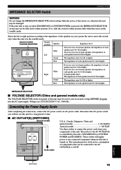
...each speaker must be 6 Ω or higher. Voltages are 110/120/220/240 V AC, 50/60 Hz. The maximum power (total power consumption of components) that can be connected to either position. If so, slide the switch to the AC OUTLET(S) is in ... of main speakers, the impedance of each speaker must be 4 Ω or higher. ADVANCED OPERATION ADDITIONAL INFORMATION APPENDIX English SWITCHED 19 IMPEDANCE SELECTOR SET BEFORE POWER ON MAIN A OR B: 4 MIN. /SPEAKER A + B: 8 MIN. /SPEAKER CENTER : 6 MIN. /SPEAKER REAR : 6 MIN. /SPEAKER MAIN A OR B: 8 MIN. /SPEAKER A + B:16 MIN. /SPEAKER...
...each speaker must be 6 Ω or higher. Voltages are 110/120/220/240 V AC, 50/60 Hz. The maximum power (total power consumption of components) that can be connected to either position. If so, slide the switch to the AC OUTLET(S) is in ... of main speakers, the impedance of each speaker must be 4 Ω or higher. ADVANCED OPERATION ADDITIONAL INFORMATION APPENDIX English SWITCHED 19 IMPEDANCE SELECTOR SET BEFORE POWER ON MAIN A OR B: 4 MIN. /SPEAKER A + B: 8 MIN. /SPEAKER CENTER : 6 MIN. /SPEAKER REAR : 6 MIN. /SPEAKER MAIN A OR B: 8 MIN. /SPEAKER A + B:16 MIN. /SPEAKER...
Owner's Manual
Page 24
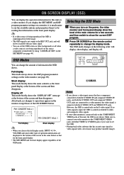
... is not being reproduced, the OSD is superimposed over the image. • The OSD signal is not shown. If no changes to turn on the power, the video monitor and front panel display show the current DSP program. 2 Press ON SCREEN on the remote control repeatedly to see page 44). y •...
... is not being reproduced, the OSD is superimposed over the image. • The OSD signal is not shown. If no changes to turn on the power, the video monitor and front panel display show the current DSP program. 2 Press ON SCREEN on the remote control repeatedly to see page 44). y •...
Owner's Manual
Page 26
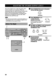
... the front panel to the center position and set PARAMETER/SET MENU on the video monitor. SPEAKERS A B Front panel 3 Set BASS and TREBLE on the power. Front panel 4 Sit in the listening position and set BASS EXTENSION to OFF. When this adjustment is important for the best performance of the main...
... the front panel to the center position and set PARAMETER/SET MENU on the video monitor. SPEAKERS A B Front panel 3 Set BASS and TREBLE on the power. Front panel 4 Sit in the listening position and set BASS EXTENSION to OFF. When this adjustment is important for the best performance of the main...
Owner's Manual
Page 28
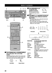
... are using two sets of the main volume for a few seconds and then switch to show the level of main speakers, press both A and B. CHAPTER + POWER REC / STOP PAUSE PLAY 6 10KEY DSP HALL 1 HALL 2 CHURCH JAZZ CLUB 1 2 3 4 ROCK CONCERT 5 STADIUM 6 ENTERTAINMENT 7 TV SPORTS 8 6.1/ES MONO ...VIDEO L AUDIO R OPTICAL SILENT VIDEO AUX BASS TREBLE - + - + 25 6 5 1 TRANSMIT RE-NAME CLEAR LEARN MACRO MACRO OFF ON SYSTEM POWER STANDBY PHONO V-AUX TUNER MD/TAPE CD-R CD D-TV/LD CBL/SAT VCR 1 VCR 2/DVR DVD 3 TITLE 6CH INPUT SOURCE DISPLAY MENU SELECT SEARCH...
... are using two sets of the main volume for a few seconds and then switch to show the level of main speakers, press both A and B. CHAPTER + POWER REC / STOP PAUSE PLAY 6 10KEY DSP HALL 1 HALL 2 CHURCH JAZZ CLUB 1 2 3 4 ROCK CONCERT 5 STADIUM 6 ENTERTAINMENT 7 TV SPORTS 8 6.1/ES MONO ...VIDEO L AUDIO R OPTICAL SILENT VIDEO AUX BASS TREBLE - + - + 25 6 5 1 TRANSMIT RE-NAME CLEAR LEARN MACRO MACRO OFF ON SYSTEM POWER STANDBY PHONO V-AUX TUNER MD/TAPE CD-R CD D-TV/LD CBL/SAT VCR 1 VCR 2/DVR DVD 3 TITLE 6CH INPUT SOURCE DISPLAY MENU SELECT SEARCH...
Owner's Manual
Page 30
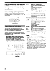
...: In this mode, only the analog input signal is selected even if a digital signal is input at the same time. When you turn on the power of this unit, the input mode is set according to "8 INPUT MODE" on the video monitor. RF: This unit only selects the Dolby Digital RF...
...: In this mode, only the analog input signal is selected even if a digital signal is input at the same time. When you turn on the power of this unit, the input mode is set according to "8 INPUT MODE" on the video monitor. RF: This unit only selects the Dolby Digital RF...


