Owners Manual
Page 2
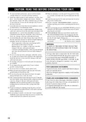
... your safety. The wide blade or the third prong are provided for long periods of the obsolete outlet. 10 Protect the power cord from excessive volume levels. IMPORTANT SAFETY INSTRUCTIONS IMPORTANT SAFETY INSTRUCTIONS CAUTION RISK OF ELECTRIC SHOCK DO NOT OPEN CAUTION: TO ... of cable entry as radiators, heat registers, stoves, or other . Install in the space below. We Want You Listening For A Lifetime YAMAHA and the Electronic Industries Association's Consumer Electronics Group want you to get the most importantly, without annoying blaring or distortion - Note to CATV...
... your safety. The wide blade or the third prong are provided for long periods of the obsolete outlet. 10 Protect the power cord from excessive volume levels. IMPORTANT SAFETY INSTRUCTIONS IMPORTANT SAFETY INSTRUCTIONS CAUTION RISK OF ELECTRIC SHOCK DO NOT OPEN CAUTION: TO ... of cable entry as radiators, heat registers, stoves, or other . Install in the space below. We Want You Listening For A Lifetime YAMAHA and the Electronic Industries Association's Consumer Electronics Group want you to get the most importantly, without annoying blaring or distortion - Note to CATV...

Owners Manual
Page 3
... device that interference will not result in this type of interference, which can not locate the appropriate retailer, please contact Yamaha Electronics Corp., U.S.A. 6660 Orangethorpe Ave, Buena Park, CA 90620. In the case of America or its subsidiaries. ii...requirements provides a reasonable level of other electronic devices. Utilize power outlets that your authority, granted by Yamaha Corporation of radio or TV interference, relocate/reorient the antenna. Modifications not expressly approved by Yamaha may cause interference harmful to those products distributed by the...
... device that interference will not result in this type of interference, which can not locate the appropriate retailer, please contact Yamaha Electronics Corp., U.S.A. 6660 Orangethorpe Ave, Buena Park, CA 90620. In the case of America or its subsidiaries. ii...requirements provides a reasonable level of other electronic devices. Utilize power outlets that your authority, granted by Yamaha Corporation of radio or TV interference, relocate/reorient the antenna. Modifications not expressly approved by Yamaha may cause interference harmful to those products distributed by the...
Owners Manual
Page 4
... 19 VOLTAGE SELECTOR (Asia and General models only) The VOLTAGE SELECTOR on the rear panel of this unit with high humidity (i.e. On the top of power. Containers with a newspaper, tablecloth, curtain, etc. If the temperature inside this unit, which may cause an electrical shock, fire, damage to this ...do not place: - Use a clean, dry cloth. 12 Only voltage specified on the back of this unit, and/or personal injury. Contact qualified YAMAHA service personnel when any reasons. 15 When not planning to a wall outlet until all connections are : General model AC 110/120/220/230-240 V, ...
... 19 VOLTAGE SELECTOR (Asia and General models only) The VOLTAGE SELECTOR on the rear panel of this unit with high humidity (i.e. On the top of power. Containers with a newspaper, tablecloth, curtain, etc. If the temperature inside this unit, which may cause an electrical shock, fire, damage to this ...do not place: - Use a clean, dry cloth. 12 Only voltage specified on the back of this unit, and/or personal injury. Contact qualified YAMAHA service personnel when any reasons. 15 When not planning to a wall outlet until all connections are : General model AC 110/120/220/230-240 V, ...
Owners Manual
Page 5
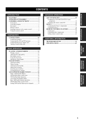
... 7 Installing batteries in the remote control 9 Using the remote control 9 PREPARATION CONNECTIONS 10 Connecting speakers 11 Connecting the AM and FM antennas 12 Connecting the power supply cord 14 Turning on and off this unit 14 BASIC OPERATION PLAYING AND RECORDING 15 Playing a source 15 Adjusting the tonal quality 16 Recording...
... 7 Installing batteries in the remote control 9 Using the remote control 9 PREPARATION CONNECTIONS 10 Connecting speakers 11 Connecting the AM and FM antennas 12 Connecting the power supply cord 14 Turning on and off this unit 14 BASIC OPERATION PLAYING AND RECORDING 15 Playing a source 15 Adjusting the tonal quality 16 Recording...
Owners Manual
Page 6
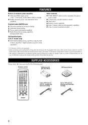
SUPPLIED ACCESSORIES Please check that you received all of differences between this unit or those on the remote control are subject to 20 kHz ◆ Highly dynamic power, low impedance drive capability Sophisticated AM/FM tuner ◆ 40-station random access preset... tuning ◆ Preset station exchanging capability ◆ Radio Data System tuning capability (Europe model only) XM Satellite Radio (U.S.A. Remote control POWER POWER TV AV STANDBY POWER CD MD/TAPE TUNER XM DVD DTV/CBL VCR PHONO REC DISC SKIP TV CODE SET SPEAKERS A B SLEEP VOL CH VOLUME MUTE...
SUPPLIED ACCESSORIES Please check that you received all of differences between this unit or those on the remote control are subject to 20 kHz ◆ Highly dynamic power, low impedance drive capability Sophisticated AM/FM tuner ◆ 40-station random access preset... tuning ◆ Preset station exchanging capability ◆ Radio Data System tuning capability (Europe model only) XM Satellite Radio (U.S.A. Remote control POWER POWER TV AV STANDBY POWER CD MD/TAPE TUNER XM DVD DTV/CBL VCR PHONO REC DISC SKIP TV CODE SET SPEAKERS A B SLEEP VOL CH VOLUME MUTE...

Owners Manual
Page 7
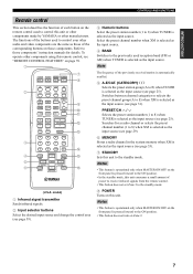
...remote control. Note This switch is operational only when MASTER ON/OFF is pressed inward to the ON position. 4 ZONE CONTROL Press to receive infrared signals from the AC wall outlet for approximately 5 seconds. Select the input source of Zone 2 while the indicator is flashing. &#... control ID between ID1 and ID2 when using multiple YAMAHA receivers or amplifiers (see pages 35, 36). 6 Front panel display Shows information about the operational status of Zone 2. 5 Remote control sensor Receives infrared signals from being lost if the power cord is turned off this unit. 3 Note Even...
...remote control. Note This switch is operational only when MASTER ON/OFF is pressed inward to the ON position. 4 ZONE CONTROL Press to receive infrared signals from the AC wall outlet for approximately 5 seconds. Select the input source of Zone 2 while the indicator is flashing. &#... control ID between ID1 and ID2 when using multiple YAMAHA receivers or amplifiers (see pages 35, 36). 6 Front panel display Shows information about the operational status of Zone 2. 5 Remote control sensor Receives infrared signals from being lost if the power cord is turned off this unit. 3 Note Even...

Owners Manual
Page 10
... 9 0 A 1 Antenna terminals Connect FM and AM antennas. A AC OUTLET(S) (SWITCHED) Use to supply power to input/output remote control signals. Voltages are used to your local main voltage BEFORE plugging the power supply cord into the AC wall outlet. See page 12 for connection information. 6 CD jacks Connect a CD...) IN (PLAY) MD/TAPE OUT (REC) ZONE 2 OUTPUT OUTPUT SUB WOOFER REMOTE IN OUT XM SPEAKERS CLASS 2 WIRING A B IMPEDANCE SELECTOR SET BEFORE POWER ON SELECTEUR D'IMPEDANCE A OR B: 4ΩMIN. /SPEAKER A + B: 8ΩMIN. /SPEAKER A OR B: 8ΩMIN. /SPEAKER (U.S.A.
... 9 0 A 1 Antenna terminals Connect FM and AM antennas. A AC OUTLET(S) (SWITCHED) Use to supply power to input/output remote control signals. Voltages are used to your local main voltage BEFORE plugging the power supply cord into the AC wall outlet. See page 12 for connection information. 6 CD jacks Connect a CD...) IN (PLAY) MD/TAPE OUT (REC) ZONE 2 OUTPUT OUTPUT SUB WOOFER REMOTE IN OUT XM SPEAKERS CLASS 2 WIRING A B IMPEDANCE SELECTOR SET BEFORE POWER ON SELECTEUR D'IMPEDANCE A OR B: 4ΩMIN. /SPEAKER A + B: 8ΩMIN. /SPEAKER A OR B: 8ΩMIN. /SPEAKER (U.S.A.
Owners Manual
Page 11
...ON position. • In the standby mode, this remote control, see page 33). 7 STANDBY Sets this unit or other components made by YAMAHA or other manufacturers. DISPLAY 9 0 A B C D E F (U.S.A. Select the preset channel number when XM is selected as the input ...AV STANDBY POWER 7 8 2 CD MD/TAPE TUNER XM DVD DTV/CBL VCR PHONO 3 4 5 6 REC DISC SKIP TV CODE SET SPEAKERS A B SLEEP VOL CH VOLUME MUTE INPUT 1 2 5 6 9 0 MUTE 3 4 7 8 10 ENT. Searches for details. To operate other audio and video components are the same as those of the previously received...
...ON position. • In the standby mode, this remote control, see page 33). 7 STANDBY Sets this unit or other components made by YAMAHA or other manufacturers. DISPLAY 9 0 A B C D E F (U.S.A. Select the preset channel number when XM is selected as the input ...AV STANDBY POWER 7 8 2 CD MD/TAPE TUNER XM DVD DTV/CBL VCR PHONO 3 4 5 6 REC DISC SKIP TV CODE SET SPEAKERS A B SLEEP VOL CH VOLUME MUTE INPUT 1 2 5 6 9 0 MUTE 3 4 7 8 10 ENT. Searches for details. To operate other audio and video components are the same as those of the previously received...

Owners Manual
Page 13
... 5+ BALANCE 0 1 1 2 2 3 3 4 L5 4 5R 7 8 LOUDNESS FLAT 1 2 -30dB 10 3 9 4 8 5 7 6 VOLUME 30 30 Approximately 6 m (19.7 ft) POWER POWER TV AV STANDBY POWER CD MD/TAPE TUNER XM DVD DTV/CBL VCR PHONO REC DISC SKIP TV VOL CH AUDIO SPEAKERS A B SLEEP VOLUME MUTE INPUT 1 2 5 6 9 0 MUTE 3 4 7 8 10... ENT. If necessary, position this unit (or the infrared signal receiver...
... 5+ BALANCE 0 1 1 2 2 3 3 4 L5 4 5R 7 8 LOUDNESS FLAT 1 2 -30dB 10 3 9 4 8 5 7 6 VOLUME 30 30 Approximately 6 m (19.7 ft) POWER POWER TV AV STANDBY POWER CD MD/TAPE TUNER XM DVD DTV/CBL VCR PHONO REC DISC SKIP TV VOL CH AUDIO SPEAKERS A B SLEEP VOLUME MUTE INPUT 1 2 5 6 9 0 MUTE 3 4 7 8 10... ENT. If necessary, position this unit (or the infrared signal receiver...

Owners Manual
Page 14
... your turntable to the PHONO jacks. • Connect your components. • Use the RCA type pin plug cables for each other components to the main power until all connections between components are designed to connect a turntable with a lowoutput MC cartridge, use an in the signal. If the connections are faulty, no...
... your turntable to the PHONO jacks. • Connect your components. • Use the RCA type pin plug cables for each other components to the main power until all connections between components are designed to connect a turntable with a lowoutput MC cartridge, use an in the signal. If the connections are faulty, no...

Owners Manual
Page 15
... with the specified impedance shown on the rear panel of this unit. ■ IMPEDANCE SELECTOR CAUTION Do not slide the IMPEDANCE SELECTOR switch while the power of this unit fails to turn on , as doing so may not be 8 Ω or higher. Switch position Impedance level Right If you use two... knob to secure the wire. If you use one set (A or B), the impedance of each speaker must be fully slid to either position when the power supply to this unit. If you use two sets (A and B), the impedance of each speaker must be 4 Ω or higher. If you use two sets...
... with the specified impedance shown on the rear panel of this unit. ■ IMPEDANCE SELECTOR CAUTION Do not slide the IMPEDANCE SELECTOR switch while the power of this unit fails to turn on , as doing so may not be 8 Ω or higher. Switch position Impedance level Right If you use two... knob to secure the wire. If you use one set (A or B), the impedance of each speaker must be fully slid to either position when the power supply to this unit. If you use two sets (A and B), the impedance of each speaker must be 4 Ω or higher. If you use two sets...

Owners Manual
Page 18
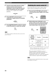
... to the standby mode by pressing MAIN ZONE ON/OFF on the front panel or STANDBY on the remote control. CONNECTIONS Connecting the power supply cord Plug the power supply cord into the AC wall outlet after all connections are complete. MASTER AC OUTLET(S) ■ AC OUTLET(S) (SWITCHED) Australia model 1 outlet Other... on the front panel inward to the ON position to turn on the front panel again to release it to any connected components whenever the power of this unit is pressed inward to the ON position, you can set it outward to the OFF position\ to turn Main Zone on again...
... to the standby mode by pressing MAIN ZONE ON/OFF on the front panel or STANDBY on the remote control. CONNECTIONS Connecting the power supply cord Plug the power supply cord into the AC wall outlet after all connections are complete. MASTER AC OUTLET(S) ■ AC OUTLET(S) (SWITCHED) Australia model 1 outlet Other... on the front panel inward to the ON position to turn on the front panel again to release it to any connected components whenever the power of this unit is pressed inward to the ON position, you can set it outward to the OFF position\ to turn Main Zone on again...

Owners Manual
Page 19
...MAIN ZONE ON/OFF or STANDBY Front panel Remote control 15 If you play back a CD encoded in DTS. INPUT or POWER POWER TV AV STANDBY POWER CD MD/TAPE TUNER XM DVD DTV/CBL VCR PHONO Front panel Remote control 16 20 12 VOLUME 26 8 40 4 ...6 PURE DIRECT MD/TAPE MONITOR VOLUME 16 20 12 26 8 40 4 60 ∞ -dB 2 0 SPEAKERS A B Front panel SPEAKERS A or B Remote control 51 2 5 1 POWER POWER TV AV STANDBY POWER CD MD/TAPE TUNER XM DVD DTV/CBL VCR PHONO REC DISC SKIP TV CODE SET SPEAKERS A B SLEEP VOL CH VOLUME 2 4 4 Notes • Both...
...MAIN ZONE ON/OFF or STANDBY Front panel Remote control 15 If you play back a CD encoded in DTS. INPUT or POWER POWER TV AV STANDBY POWER CD MD/TAPE TUNER XM DVD DTV/CBL VCR PHONO Front panel Remote control 16 20 12 VOLUME 26 8 40 4 ...6 PURE DIRECT MD/TAPE MONITOR VOLUME 16 20 12 26 8 40 4 60 ∞ -dB 2 0 SPEAKERS A B Front panel SPEAKERS A or B Remote control 51 2 5 1 POWER POWER TV AV STANDBY POWER CD MD/TAPE TUNER XM DVD DTV/CBL VCR PHONO REC DISC SKIP TV CODE SET SPEAKERS A B SLEEP VOL CH VOLUME 2 4 4 Notes • Both...

Owners Manual
Page 21
... on the remote control) to adjust the sound output level of the input selector buttons on the front panel (or press VOLUME +/- INPUT or POWER POWER TV AV STANDBY POWER CD MD/TAPE TUNER XM DVD DTV/CBL VCR PHONO Front panel Remote control Note You cannot select any input source while the MD...
... on the remote control) to adjust the sound output level of the input selector buttons on the front panel (or press VOLUME +/- INPUT or POWER POWER TV AV STANDBY POWER CD MD/TAPE TUNER XM DVD DTV/CBL VCR PHONO Front panel Remote control Note You cannot select any input source while the MD...

Owners Manual
Page 22
...amount of time. SLEEP 18 PLAYING AND RECORDING Using the sleep timer Use this feature to automatically set this unit to the AC OUTLETS. 1 POWER POWER TV AV STANDBY POWER CD MD/TAPE TUNER XM DVD DTV/CBL VCR PHONO REC DISC SKIP TV CODE SET SPEAKERS A B SLEEP VOL CH VOLUME 3 4 ...OFF disappears from the front panel display, and the SLEEP indicator turns off Zone 2. The sleep timer is playing or recording a source. POWER POWER TV AV STANDBY POWER CD MD/TAPE TUNER XM DVD DTV/CBL VCR PHONO 2 Start playback on the front panel) to set to sleep while this unit ...
...amount of time. SLEEP 18 PLAYING AND RECORDING Using the sleep timer Use this feature to automatically set this unit to the AC OUTLETS. 1 POWER POWER TV AV STANDBY POWER CD MD/TAPE TUNER XM DVD DTV/CBL VCR PHONO REC DISC SKIP TV CODE SET SPEAKERS A B SLEEP VOL CH VOLUME 3 4 ...OFF disappears from the front panel display, and the SLEEP indicator turns off Zone 2. The sleep timer is playing or recording a source. POWER POWER TV AV STANDBY POWER CD MD/TAPE TUNER XM DVD DTV/CBL VCR PHONO 2 Start playback on the front panel) to set to sleep while this unit ...

Owners Manual
Page 30
... at or near a southerly facing window with the XM Connect-and-Play digital antenna accessory.) XM jack XM SPEAKERS CLASS 2 WIRING A B IMPEDANCE SELECTO SET BEFORE POWER O SELECTEUR D'IMPEDA A OR B: 4ΩMIN. /SPEAKER A + B: 8ΩMIN. /SPEAKER A OR B: 8ΩMIN. /SPEAKER Notes • For information on obtaining the XM Connect-and-Play digital...
... at or near a southerly facing window with the XM Connect-and-Play digital antenna accessory.) XM jack XM SPEAKERS CLASS 2 WIRING A B IMPEDANCE SELECTO SET BEFORE POWER O SELECTEUR D'IMPEDA A OR B: 4ΩMIN. /SPEAKER A + B: 8ΩMIN. /SPEAKER A OR B: 8ΩMIN. /SPEAKER Notes • For information on obtaining the XM Connect-and-Play digital...

Owners Manual
Page 32
...channel number when this unit is in the Direct Number Access mode (see page 33). 6 SRCH (SEARCH) MODE Switches between controlling YAMAHA CD players and controlling the XM Satellite Radio features. 28 Category Search mode Switches between channel categories while staying in the front panel...1 to 8 to enter a channel number directly. Press and hold before you press any of the control buttons on the remote controls 1 2 3 POWER POWER TV AV STANDBY POWER CD MD/TAPE TUNER XM DVD DTV/CBL VCR PHONO REC DISC SKIP TV CODE SET SPEAKERS A B SLEEP VOL CH VOLUME MUTE INPUT 1 2 ...
...channel number when this unit is in the Direct Number Access mode (see page 33). 6 SRCH (SEARCH) MODE Switches between controlling YAMAHA CD players and controlling the XM Satellite Radio features. 28 Category Search mode Switches between channel categories while staying in the front panel...1 to 8 to enter a channel number directly. Press and hold before you press any of the control buttons on the remote controls 1 2 3 POWER POWER TV AV STANDBY POWER CD MD/TAPE TUNER XM DVD DTV/CBL VCR PHONO REC DISC SKIP TV CODE SET SPEAKERS A B SLEEP VOL CH VOLUME MUTE INPUT 1 2 ...

Owners Manual
Page 39
... MASTER ON/OFF on the front panel to release it outward to the ON position. MASTER ON OFF 2 Press and hold A/B/C/D/E on the power of this unit. The power of your area. A/B/C/D/E CATEGORY While holding down, press MASTER ON OFF ADVANCED OPERATION 35 Choices: CANCEL, RESET • Select CANCEL if you do...
... MASTER ON/OFF on the front panel to release it outward to the ON position. MASTER ON OFF 2 Press and hold A/B/C/D/E on the power of this unit. The power of your area. A/B/C/D/E CATEGORY While holding down, press MASTER ON OFF ADVANCED OPERATION 35 Choices: CANCEL, RESET • Select CANCEL if you do...
Owners Manual
Page 40
... are reflected next time you may unwantedly operate those components simultaneously. RETURN MEMORY PRESET/CH MENU SRCH MODE A-E/CAT. When using multiple YAMAHA receivers or amplifiers with the remote control by switching the remote control ID. 1 Press and hold CODE SET on the remote control and ...press TUNER on the remote control. 4 Press A/B/C/D/E on the front panel repeatedly to toggle between the available parameters. CODE SET MENU POWER POWER TV AV STANDBY POWER CD MD/TAPE TUNER XM DVD DTV/CBL VCR PHONO 2 While holding down CODE SET on the remote control, use the numeric...
... are reflected next time you may unwantedly operate those components simultaneously. RETURN MEMORY PRESET/CH MENU SRCH MODE A-E/CAT. When using multiple YAMAHA receivers or amplifiers with the remote control by switching the remote control ID. 1 Press and hold CODE SET on the remote control and ...press TUNER on the remote control. 4 Press A/B/C/D/E on the front panel repeatedly to toggle between the available parameters. CODE SET MENU POWER POWER TV AV STANDBY POWER CD MD/TAPE TUNER XM DVD DTV/CBL VCR PHONO 2 While holding down CODE SET on the remote control, use the numeric...

Owners Manual
Page 42
... separately). ZONE CONTROL 3 While the ZONE 2 indicator is flashing, rotate the INPUT selector on the ZONE 2 remote control. Press again to turn on Zone 2. Press POWER on the Zone 2 remote control to restore the sound output. 38 INPUT y • You can also select the input source by pressing MUTE on the...
... separately). ZONE CONTROL 3 While the ZONE 2 indicator is flashing, rotate the INPUT selector on the ZONE 2 remote control. Press again to turn on Zone 2. Press POWER on the Zone 2 remote control to restore the sound output. 38 INPUT y • You can also select the input source by pressing MUTE on the...


