
Owner's Manual
Page 3
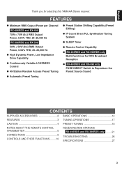
... 18 NOTES ABOUT THE REMOTE CONTROL TRANSMITTER 5 CONNECTIONS 6 CONTROLS AND THEIR FUNCTIONS ........10 RECEIVING RDS STATIONS RX-496RDS and RX-396RDS only .........21 TROUBLESHOOTING 26 SPECIFICATIONS 27 3 FEATURES q Minimum RMS Output Power per Channel RX-496RDS and RX-496 75W + 75W (8Ω) RMS Output Power, 0.04% THD, 20-20,000 Hz RX-396RDS and RX-396 50W + 50W (8Ω) RMS...
... 18 NOTES ABOUT THE REMOTE CONTROL TRANSMITTER 5 CONNECTIONS 6 CONTROLS AND THEIR FUNCTIONS ........10 RECEIVING RDS STATIONS RX-496RDS and RX-396RDS only .........21 TROUBLESHOOTING 26 SPECIFICATIONS 27 3 FEATURES q Minimum RMS Output Power per Channel RX-496RDS and RX-496 75W + 75W (8Ω) RMS Output Power, 0.04% THD, 20-20,000 Hz RX-396RDS and RX-396 50W + 50W (8Ω) RMS...
Owner's Manual
Page 5
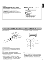
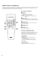
...ON A NOTES ABOUT THE REMOTE CONTROL TRANSMITTER Battery installation Remote control transmitter operation range 2 1 3 l6 20 28 l2 8 40 4 60 2 0 -dB Remote control sensor Battery replacement If you find that the remote control transmitter must be no large obstacles between the remote control transmitter and the main unit....R6, UM-3 batteries for an extended period of fluorescent lamp etc.), it come in the standby mode. q If the remote control sensor is directly illuminated by strong lighting (especially an inverter type of time. In this unit may not be damaged....
...ON A NOTES ABOUT THE REMOTE CONTROL TRANSMITTER Battery installation Remote control transmitter operation range 2 1 3 l6 20 28 l2 8 40 4 60 2 0 -dB Remote control sensor Battery replacement If you find that the remote control transmitter must be no large obstacles between the remote control transmitter and the main unit....R6, UM-3 batteries for an extended period of fluorescent lamp etc.), it come in the standby mode. q If the remote control sensor is directly illuminated by strong lighting (especially an inverter type of time. In this unit may not be damaged....
Owner's Manual
Page 6
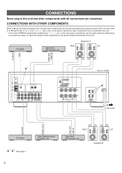
... be sure all connections are made correctly, that is to say L (left) to L, R (right) to R, "+" to "+" and "-" to "-". FM ANT GND AM ANT GND REMOTE CONTROL IN OUT PHONO CD AUX TAPE 1 PLAY /MD REC TAPE 2 PLAY REC 1 3 4 3 or 5 4 or 6 AUDIO SIGNAL A OR B:4ΩMIN. /SPEAKER A B:8Ω... components until all connections are completed. CONNECTIONS Never plug in this unit and other components, be connected to this unit. * If you have YAMAHA components numbered as 1, 3, 4, etc. Speakers A Right Left OUTPUT GND LINE OUT LINE IN 2 * 75Ω UNBAL. CONNECTIONS WITH ...
... be sure all connections are made correctly, that is to say L (left) to L, R (right) to R, "+" to "+" and "-" to "-". FM ANT GND AM ANT GND REMOTE CONTROL IN OUT PHONO CD AUX TAPE 1 PLAY /MD REC TAPE 2 PLAY REC 1 3 4 3 or 5 4 or 6 AUDIO SIGNAL A OR B:4ΩMIN. /SPEAKER A B:8Ω... components until all connections are completed. CONNECTIONS Never plug in this unit and other components, be connected to this unit. * If you have YAMAHA components numbered as 1, 3, 4, etc. Speakers A Right Left OUTPUT GND LINE OUT LINE IN 2 * 75Ω UNBAL. CONNECTIONS WITH ...

Owner's Manual
Page 7
...the wire. How to either the SPEAKERS A or B terminals. 7 If you use ) Connecting the ground wire of components) that is controlled by this unit. The power to any metal part of the speaker wires is correct, that can be obtained with the ground wire disconnected.... These outlets will normally minimize hum, but in some cases better results may be connected to this unit's STANDBY/ON switch or the provided remote control transmitter's STANDBY/ON key. The maximum power (total power consumption of the turntable to your components to this unit. English 1 *AC OUTLETS ...
...the wire. How to either the SPEAKERS A or B terminals. 7 If you use ) Connecting the ground wire of components) that is controlled by this unit. The power to any metal part of the speaker wires is correct, that can be obtained with the ground wire disconnected.... These outlets will normally minimize hum, but in some cases better results may be connected to this unit's STANDBY/ON switch or the provided remote control transmitter's STANDBY/ON key. The maximum power (total power consumption of the turntable to your components to this unit. English 1 *AC OUTLETS ...
Owner's Manual
Page 8
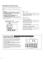
...terminal of the other component, you can also operate the component with the system remote control. Connect the REMOTE CONTROL IN terminal of this unit to the REMOTE CONTROL IN terminal of the central controller for custom installation system. If you use two pairs of speakers, the impedance ...of speakers, the impedance of each speaker must be 4Ω or higher. For Custom Installer For U.S.A., Canada and Australia models only REMOTE CONTROL (IN, OUT) terminals These terminals are used for custom installation system, you use one pair of speakers, the impedance of each...
...terminal of the other component, you can also operate the component with the system remote control. Connect the REMOTE CONTROL IN terminal of this unit to the REMOTE CONTROL IN terminal of the central controller for custom installation system. If you use two pairs of speakers, the impedance ...of speakers, the impedance of each speaker must be 4Ω or higher. For Custom Installer For U.S.A., Canada and Australia models only REMOTE CONTROL (IN, OUT) terminals These terminals are used for custom installation system, you use one pair of speakers, the impedance of each...
Owner's Manual
Page 11
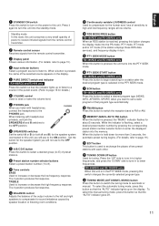
... and RX-396RDS only Press this button to begin searching for details.) 6 VOLUME control Used to raise or lower the volume level. 7 PHONES jack When you will not use to the ON position. K TUNING DOWN/UP button Used for the human ears' loss of power to receive infrared-signals from the remote control transmitter. 2 Remote control...
... and RX-396RDS only Press this button to begin searching for details.) 6 VOLUME control Used to raise or lower the volume level. 7 PHONES jack When you will not use to the ON position. K TUNING DOWN/UP button Used for the human ears' loss of power to receive infrared-signals from the remote control transmitter. 2 Remote control...
Owner's Manual
Page 12
... alternately. 4 Input selector keys Select input source. 5 VOLUME +/- On each component. 1 1 2 2 3 YAMAHA HiFi SYSTEM REMOTE CONTROL TRANSMITTER AUX DIR A DIR B REC/PAUSE PLAY TAPE 2 A/B TAPE 1 - If these keys are YAMAHA components designed for remote control compatibility, this remote control transmitter will be the same. REMOTE CONTROL TRANSMITTER The remote control transmitter provided with automatic reverse function, pressing DIR A will reverse the direction...
... alternately. 4 Input selector keys Select input source. 5 VOLUME +/- On each component. 1 1 2 2 3 YAMAHA HiFi SYSTEM REMOTE CONTROL TRANSMITTER AUX DIR A DIR B REC/PAUSE PLAY TAPE 2 A/B TAPE 1 - If these keys are YAMAHA components designed for remote control compatibility, this remote control transmitter will be the same. REMOTE CONTROL TRANSMITTER The remote control transmitter provided with automatic reverse function, pressing DIR A will reverse the direction...
Owner's Manual
Page 14
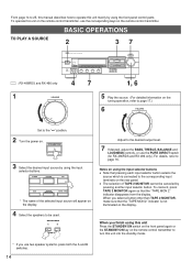
... Adjust to be canceled by using this unit Press the STANDBY/ON switch on the front panel again or the STANDBY/ON key on the remote control transmitter to turn this unit into the standby mode. * If you use two speaker systems, press both the A and B switches. 14 For ...8 40 4 60 2 0 -dB : RX-496RDS and RX-496 only 47 1, 6 1 VOLUME l6 20 l2 28 8 40 4 60 2 0 -dB Set to page 16. From page 14 to 25, this manual describes how to operate this unit on the remote control transmitter, use the corresponding keys on the remote control transmitter. When you select a button other...
... Adjust to be canceled by using this unit Press the STANDBY/ON switch on the front panel again or the STANDBY/ON key on the remote control transmitter to turn this unit into the standby mode. * If you use two speaker systems, press both the A and B switches. 14 For ...8 40 4 60 2 0 -dB : RX-496RDS and RX-496 only 47 1, 6 1 VOLUME l6 20 l2 28 8 40 4 60 2 0 -dB Set to page 16. From page 14 to 25, this manual describes how to operate this unit on the remote control transmitter, use the corresponding keys on the remote control transmitter. When you select a button other...
Owner's Manual
Page 26
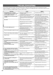
...cannot be tuned in the evening). A desired station cannot be tuned in the SYMPTOM column, disconnect the power cord and contact your authorized YAMAHA dealer or service center for a long period. There are not secure. There are connected in the correct phase (+ and -). CAUSE Power...the AM loop antenna connections and rotate it cannot be corrected by the simple measures suggested. Change the position of the BALANCE control. The remote control transmitter does not work normally. Incorrect cord connections. Connect the speaker wires in reverse to the GND terminal. If the ...
...cannot be tuned in the evening). A desired station cannot be tuned in the SYMPTOM column, disconnect the power cord and contact your authorized YAMAHA dealer or service center for a long period. There are not secure. There are connected in the correct phase (+ and -). CAUSE Power...the AM loop antenna connections and rotate it cannot be corrected by the simple measures suggested. Change the position of the BALANCE control. The remote control transmitter does not work normally. Incorrect cord connections. Connect the speaker wires in reverse to the GND terminal. If the ...


