
Owners Manual
Page 9
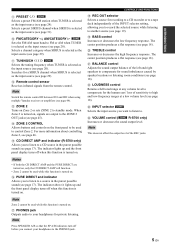
...using multiple Yamaha receivers or amplifiers (see page 19). C ZONE 2 Turns on the front panel to be used to the ZONE 2 OUT jacks (see page 17). When Zone 2 is turned on , signals are turned on . CONTROLS AND FUNCTIONS H REC OUT selector Selects a source for sound imbalances caused by speaker... locations or listening room conditions (see page 46. Note Zone 2 cannot be used while this function is selected as the input source (see page 24). Selects...
...using multiple Yamaha receivers or amplifiers (see page 19). C ZONE 2 Turns on the front panel to be used to the ZONE 2 OUT jacks (see page 17). When Zone 2 is turned on , signals are turned on . CONTROLS AND FUNCTIONS H REC OUT selector Selects a source for sound imbalances caused by speaker... locations or listening room conditions (see page 46. Note Zone 2 cannot be used while this function is selected as the input source (see page 24). Selects...
Owners Manual
Page 11
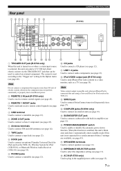
...). 8 DOCK jack Used to connect an optional Yamaha Universal Dock for iPod (YID-W10), or Bluetooth Wireless Audio Receiver (YBA-10) (see page 35). 9 PHONO jacks Used to connect a turntable (see page 12). 0 CD jacks Used to connect a subwoofer with built-in the Option menu (see page 43). H IMPEDANCE SELECTOR switch Used to connect speakers (see page...
...). 8 DOCK jack Used to connect an optional Yamaha Universal Dock for iPod (YID-W10), or Bluetooth Wireless Audio Receiver (YBA-10) (see page 35). 9 PHONO jacks Used to connect a turntable (see page 12). 0 CD jacks Used to connect a subwoofer with built-in the Option menu (see page 43). H IMPEDANCE SELECTOR switch Used to connect speakers (see page...

Owners Manual
Page 12
...Switches the zone to be used no matter which input source is pressed. 9 MUTE Mutes the sound output. C CODE SET/RECEIVER Used to program the remote control so that can be operated by Yamaha or other external components ... 2 (see page 46). 5 SLEEP Sets the sleep timer (see page 19). 6 Input selector buttons Selects the input source and changes the control area (see page 47). 7 OPTION Turns the ...OPTION menu on and off (see page 40). 8 SPEAKERS A/B Turns on and off the set of speakers connected to the SPEAKERS A and/or SPEAKERS B terminals on the rear panel of the REC jacks. For ...
...Switches the zone to be used no matter which input source is pressed. 9 MUTE Mutes the sound output. C CODE SET/RECEIVER Used to program the remote control so that can be operated by Yamaha or other external components ... 2 (see page 46). 5 SLEEP Sets the sleep timer (see page 19). 6 Input selector buttons Selects the input source and changes the control area (see page 47). 7 OPTION Turns the ...OPTION menu on and off (see page 40). 8 SPEAKERS A/B Turns on and off the set of speakers connected to the SPEAKERS A and/or SPEAKERS B terminals on the rear panel of the REC jacks. For ...
Owners Manual
Page 16
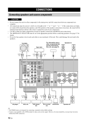
...or other or any metal part of this unit. See page 13 for speaker connections and DOCK jack connections). • The IMPEDANCE SELECTOR must be connected to reduce noise in Audio out CD player VCR, etc. Speakers A Audio out Audio GND out Audio in Audio out Audio out Audio ...an MM cartridge. • Connect your components. • Use RCA cables for audio components (except for details. • Do not let bare speaker wires touch each of the speaker connections is incorrect, the sound will be heard from the speakers, and if the polarity of your turntable to the GND terminal...
...or other or any metal part of this unit. See page 13 for speaker connections and DOCK jack connections). • The IMPEDANCE SELECTOR must be connected to reduce noise in Audio out CD player VCR, etc. Speakers A Audio out Audio GND out Audio in Audio out Audio out Audio ...an MM cartridge. • Connect your components. • Use RCA cables for audio components (except for details. • Do not let bare speaker wires touch each of the speaker connections is incorrect, the sound will be heard from the speakers, and if the polarity of your turntable to the GND terminal...

Owners Manual
Page 17
... plug Tighten the knob and then insert the banana plug into the speaker terminals, insert only the bare speaker wire. y To use one set of terminals. Select the switch position (LOW or HIGH) according to the impedance of the speakers in your speakers: 6 Ω or higher: HIGH (R-S700) 8 Ω or higher:...of insulation from the combined midrange and tweeter section. Note When inserting speaker cables into the end of the corresponding terminal. These two sets of terminals allow the speaker to the other set the IMPEDANCE SELECTOR switch to HIGH or LOW depending on , as doing so may ...
... plug Tighten the knob and then insert the banana plug into the speaker terminals, insert only the bare speaker wire. y To use one set of terminals. Select the switch position (LOW or HIGH) according to the impedance of the speakers in your speakers: 6 Ω or higher: HIGH (R-S700) 8 Ω or higher:...of insulation from the combined midrange and tweeter section. Note When inserting speaker cables into the end of the corresponding terminal. These two sets of terminals allow the speaker to the other set the IMPEDANCE SELECTOR switch to HIGH or LOW depending on , as doing so may ...
Owners Manual
Page 20
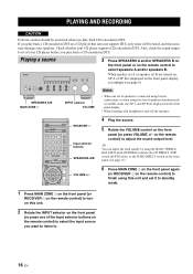
... A on the remote control) to finish using this unit. 2 Rotate the INPUT selector on the front panel (or press one set it to adjust the sound output level. y You can adjust the tonal quality by using two sets of speakers is connected using bi-wire connections, or when using the BASS, TREBLE, BALANCE and LOUDNESS controls...
... A on the remote control) to finish using this unit. 2 Rotate the INPUT selector on the front panel (or press one set it to adjust the sound output level. y You can adjust the tonal quality by using two sets of speakers is connected using bi-wire connections, or when using the BASS, TREBLE, BALANCE and LOUDNESS controls...

Owners Manual
Page 54
... activated Check that the IMPEDANCE SELECTOR switch is not set to either end. Make sure the openings on . phase. Connect the power cable firmly. Set this unit to standby mode, disconnect the power cable, plug it back in after 30 seconds, then use it is incorrect. SPEAKERS B. Incorrect setting for the... Refer to the chart below do not help, set this unit to standby mode, disconnect the power cable, and contact the nearest authorized Yamaha dealer or service center. ■ General Problem Cause Remedy This unit fails to turn The power cable is not completely inserted.
... activated Check that the IMPEDANCE SELECTOR switch is not set to either end. Make sure the openings on . phase. Connect the power cable firmly. Set this unit to standby mode, disconnect the power cable, plug it back in after 30 seconds, then use it is incorrect. SPEAKERS B. Incorrect setting for the... Refer to the chart below do not help, set this unit to standby mode, disconnect the power cable, and contact the nearest authorized Yamaha dealer or service center. ■ General Problem Cause Remedy This unit fails to turn The power cable is not completely inserted.


