Owner's Manual
Page 2
...two blades with the letter L or coloured RED. • This applies only to products distributed by Yamaha-Kemble Music (U.K.) Ltd. (3 wires) receptacles, and the point where they exit from tip-over. 13...of electric shock to constitute a risk of time. 14 Refer all instructions. 5 Do not use this apparatus near any heat sources such as powersupply cord or plug is damaged, liquid has... heat registers, stoves, or other . Servicing is marked with one wider than the other apparatus (including amplifiers) that produce heat. 9 Do not defeat the safety purpose of the wires in such a way that...
...two blades with the letter L or coloured RED. • This applies only to products distributed by Yamaha-Kemble Music (U.K.) Ltd. (3 wires) receptacles, and the point where they exit from tip-over. 13...of electric shock to constitute a risk of time. 14 Refer all instructions. 5 Do not use this apparatus near any heat sources such as powersupply cord or plug is damaged, liquid has... heat registers, stoves, or other . Servicing is marked with one wider than the other apparatus (including amplifiers) that produce heat. 9 Do not defeat the safety purpose of the wires in such a way that...

Owner's Manual
Page 3
... that receive direct sunlight. - Operation ● Do not scratch, bend, twist, pull, or heat the power cord. If you continue using the unit without heeding this unit for normal ventilation. Remove the power cord from the following locations: - Locations exposed to a heater. place...down, - Never pull the cord. This should be an electrical shock hazard. You could receive an electrical shock. Operation ● Use only speaker cables when connecting speakers to this unit. Leaving it is a fire and electrical shock hazard. ● If lightning...
... that receive direct sunlight. - Operation ● Do not scratch, bend, twist, pull, or heat the power cord. If you continue using the unit without heeding this unit for normal ventilation. Remove the power cord from the following locations: - Locations exposed to a heater. place...down, - Never pull the cord. This should be an electrical shock hazard. You could receive an electrical shock. Operation ● Use only speaker cables when connecting speakers to this unit. Leaving it is a fire and electrical shock hazard. ● If lightning...
Owner's Manual
Page 4
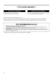
... could void your authority, granted by YAMAHA CORPORATION OF AMERICA. 4 Follow all installation instructions. Pin 2: hot (+); FCC INFORMATION (U.S.A.) 1. Failure to use the product. 2. IMPORTANT NOTICE: DO NOT MODIFY THIS UNIT! Cable/s supplied with this product in use only high quality shielded cables. This ... the amplifier is not in the USA. * This applies only to products (P7000S, P5000S) distributed by the FCC, to accessories and/or another product use . Illustrations in this manual are for explanatory purposes only, and may induce noise. IMPORTANT: When ...
... could void your authority, granted by YAMAHA CORPORATION OF AMERICA. 4 Follow all installation instructions. Pin 2: hot (+); FCC INFORMATION (U.S.A.) 1. Failure to use the product. 2. IMPORTANT NOTICE: DO NOT MODIFY THIS UNIT! Cable/s supplied with this product in use only high quality shielded cables. This ... the amplifier is not in the USA. * This applies only to products (P7000S, P5000S) distributed by the FCC, to accessories and/or another product use . Illustrations in this manual are for explanatory purposes only, and may induce noise. IMPORTANT: When ...

Owner's Manual
Page 5
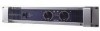
... come. After reading through this manual carefully before beginning use, so that you for your purchase of the YAMAHA P7000S, P5000S, P3500S or P2500S power amplifier. This Owner's Manual covers the four models: P7000S, P5000S, P3500S and P2500S power amplifiers. These ...P-series amplifiers fully incorporate Yamaha's renown technological expertise, and offer high reliability, rock-solid stability, and superb acoustic characteristics-...
... come. After reading through this manual carefully before beginning use, so that you for your purchase of the YAMAHA P7000S, P5000S, P3500S or P2500S power amplifier. This Owner's Manual covers the four models: P7000S, P5000S, P3500S and P2500S power amplifiers. These ...P-series amplifiers fully incorporate Yamaha's renown technological expertise, and offer high reliability, rock-solid stability, and superb acoustic characteristics-...

Owner's Manual
Page 6
... this indicator is lit up green when the corresponding channel's output level exceeds 2 Vrms (equivalent to 1/2 W into an 8 Ω load, or 1 W into place using the same screws. 7 indicator Lights up if the heat sink overheats, or if a DC voltage is too high. 5 SIGNAL indicator Lights up . NOTE: The fans... the knobs so that the settings will not be sure that protection is set ON. (See page 7.) 8 Air intakes The amplifier uses forced-air cooling. Specifically, lights up yellow if the YS PROCESSING switch on automatically when the temperature of the heat sink rises above...
... this indicator is lit up green when the corresponding channel's output level exceeds 2 Vrms (equivalent to 1/2 W into an 8 Ω load, or 1 W into place using the same screws. 7 indicator Lights up if the heat sink overheats, or if a DC voltage is too high. 5 SIGNAL indicator Lights up . NOTE: The fans... the knobs so that the settings will not be sure that protection is set ON. (See page 7.) 8 Air intakes The amplifier uses forced-air cooling. Specifically, lights up yellow if the YS PROCESSING switch on automatically when the temperature of the heat sink rises above...

Owner's Manual
Page 7
...- 1+ +1- 1+ + 1- - 2+ + 2- - (-) (+) BRIDGE 43 6 1 FILTER switch and FREQUENCY adjustment knob (One pair for each channel) Use these controls to select the filter type and adjust the cutoff frequency on speakers such as the YAMAHA S112 and S115. 3 INPUT jacks (Channels A, B) Two jack types are lower than the cutoff set this... wired as shown below. The adjustment range is set to BRIDGE mode, only the switch and knob for each channel (A and B). Use a low-pass filter. The results (the actual change in the low-frequency balance) will vary accord- NOTE: This feature ...
...- 1+ +1- 1+ + 1- - 2+ + 2- - (-) (+) BRIDGE 43 6 1 FILTER switch and FREQUENCY adjustment knob (One pair for each channel) Use these controls to select the filter type and adjust the cutoff frequency on speakers such as the YAMAHA S112 and S115. 3 INPUT jacks (Channels A, B) Two jack types are lower than the cutoff set this... wired as shown below. The adjustment range is set to BRIDGE mode, only the switch and knob for each channel (A and B). Use a low-pass filter. The results (the actual change in the low-frequency balance) will vary accord- NOTE: This feature ...

Owner's Manual
Page 8
...be independently adjusted. • BRIDGE mode The Channel A input signal is output through both the Channel A and Channel B output jacks. If you must use this switch to select the operating mode. • STEREO mode Channels A and B operate independently (as with a conventional stereo amplifier). The ...Channel B input jacks do not function. 4 STEREO/PARALLEL/BRIDGE switch Use this terminal to connect to ground or to connect to the chassis of the mixer, preamp, or other device in your system. 8
...be independently adjusted. • BRIDGE mode The Channel A input signal is output through both the Channel A and Channel B output jacks. If you must use this switch to select the operating mode. • STEREO mode Channels A and B operate independently (as with a conventional stereo amplifier). The ...Channel B input jacks do not function. 4 STEREO/PARALLEL/BRIDGE switch Use this terminal to connect to ground or to connect to the chassis of the mixer, preamp, or other device in your system. 8
Owner's Manual
Page 9
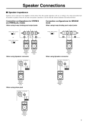
... post output jacks STEREO BRIDGE PARALLEL or STEREO BRIDGE PARALLEL - 1+ +1- (-) (+) BRIDGE STEREO BRIDGE PARALLEL - 1+ +1- (-) (+) BRIDGE Minimum speaker impedance: 4 Ω When using phone jack LOCK LOCK SPEAKERS 3 2 23 + 1+ - 1- 1+ + 1- - 2+ + 2- - Minimum speaker impedance: 8 Ω When using Speakon connector LOCK LOCK SPEAKERS 3 2 23 + 1+ - 1- 1+ + 1- - 2+ + 2- - Minimum speaker impedance: 8 Ω Minimum speaker impedance: 4 Ω 9 Speaker Connections ■ Speaker impedance...
... post output jacks STEREO BRIDGE PARALLEL or STEREO BRIDGE PARALLEL - 1+ +1- (-) (+) BRIDGE STEREO BRIDGE PARALLEL - 1+ +1- (-) (+) BRIDGE Minimum speaker impedance: 4 Ω When using phone jack LOCK LOCK SPEAKERS 3 2 23 + 1+ - 1- 1+ + 1- - 2+ + 2- - Minimum speaker impedance: 8 Ω When using Speakon connector LOCK LOCK SPEAKERS 3 2 23 + 1+ - 1- 1+ + 1- - 2+ + 2- - Minimum speaker impedance: 8 Ω Minimum speaker impedance: 4 Ω 9 Speaker Connections ■ Speaker impedance...

Owner's Manual
Page 10
... the speaker terminals. B- tective cover from the end of each speaker cable, and pass the bare wire through the holes in the USA: Please use Class 3 wiring. (P7000S, P5000S) Please use Class 2 wiring. (P3500S, P2500S) Be sure that the bare wire ends do not jut out from the terminals and touch the chassis.
... the speaker terminals. B- tective cover from the end of each speaker cable, and pass the bare wire through the holes in the USA: Please use Class 3 wiring. (P7000S, P5000S) Please use Class 2 wiring. (P3500S, P2500S) Be sure that the bare wire ends do not jut out from the terminals and touch the chassis.

Owner's Manual
Page 11
Also be sure to install ventilation panel(s) as shown below. Note: EIA stands for Electronic Industries Alliance. Ventilation panel(s) Use 1U-size blank panel(s). 480 44 Unit: mm If mounting up to four amplifiers in an open -backed rack, and when mounting any ... and below each amplifer. Rack Mounting Mounting in a standard EIA rack If you are mounting multiple power amplifiers in a rack, be sure to use metal brackets (one on each side) to support the rear of each amplifier, as shown below . Ventilation panel (Attach to the front or...
Also be sure to install ventilation panel(s) as shown below. Note: EIA stands for Electronic Industries Alliance. Ventilation panel(s) Use 1U-size blank panel(s). 480 44 Unit: mm If mounting up to four amplifiers in an open -backed rack, and when mounting any ... and below each amplifer. Rack Mounting Mounting in a standard EIA rack If you are mounting multiple power amplifiers in a rack, be sure to use metal brackets (one on each side) to support the rear of each amplifier, as shown below . Ventilation panel (Attach to the front or...

Owner's Manual
Page 15
... lights. P3500S, P2500S Indicator(s) PROTECTION indicator lights. The relay operates to [W]. P7000S, P5000S Indicator(s) Possible Cause Remedy Protection Circuit Power has been shut down. (All indicators are off...at least 4 Ω (STEREO/PARALLEL mode) or 8 Ω (BRIDGE mode). Use a speaker system with occasional clipping. Check the ventilation slots, and provide better airfl...take appropriate measures to protect the speaker system. 15 Consult your dealer or the nearest Yamaha service center. The protection circuitry shut off .) A DC voltage of ± ...
... lights. P3500S, P2500S Indicator(s) PROTECTION indicator lights. The relay operates to [W]. P7000S, P5000S Indicator(s) Possible Cause Remedy Protection Circuit Power has been shut down. (All indicators are off...at least 4 Ω (STEREO/PARALLEL mode) or 8 Ω (BRIDGE mode). Use a speaker system with occasional clipping. Check the ventilation slots, and provide better airfl...take appropriate measures to protect the speaker system. 15 Consult your dealer or the nearest Yamaha service center. The protection circuitry shut off .) A DC voltage of ± ...


