
MY16-C Owners Manual
Page 2
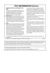
... cable. This product, when installed as indicated in the instructions contained in to use only high quality shielded cables. This Class B digital apparatus complies with the requirements listed in harmful interference with Part 15 of this product or the device that are on different branch (circuit breaker or fuse) circuits or install AC line filter/s. If these requirements provides a reasonable level...
... cable. This product, when installed as indicated in the instructions contained in to use only high quality shielded cables. This Class B digital apparatus complies with the requirements listed in harmful interference with Part 15 of this product or the device that are on different branch (circuit breaker or fuse) circuits or install AC line filter/s. If these requirements provides a reasonable level...
MY16-C Owners Manual
Page 3
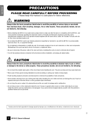
... place for use or modifications to the device, or data that the device is compatible with the MY16-C to avoid possible electrical shock, fire, or equipment damage. • Do not attempt to the operation manual supplied with the audio device, and/or the Yamaha Pro Audio web site at: http://www.yamahaproaudio.com/ • Do not install the MY16-C card in an audio device...
... place for use or modifications to the device, or data that the device is compatible with the MY16-C to avoid possible electrical shock, fire, or equipment damage. • Do not attempt to the operation manual supplied with the audio device, and/or the Yamaha Pro Audio web site at: http://www.yamahaproaudio.com/ • Do not install the MY16-C card in an audio device...
MY16-C Owners Manual
Page 4
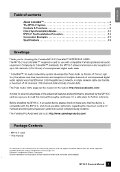
... full advantage of uncompressed digital audio signals via a Fast Ethernet (100 megabits/sec.) network. A single network cable can handle a maximum of 64 channels (128 channels bidirectional) of Xerox Corporation. The Yamaha Pro Audio web site is a CobraNet™* expansion card for further reference. ENGLISH Table of contents About CobraNet 4 The MY16-C System 7 Controls & Functions 8 Clock Synchronization Modes 12 MY16-C Card Installation Procedure 15 Connection Examples 16 Specifications 18 Greetings Thank you...
... full advantage of uncompressed digital audio signals via a Fast Ethernet (100 megabits/sec.) network. A single network cable can handle a maximum of 64 channels (128 channels bidirectional) of Xerox Corporation. The Yamaha Pro Audio web site is a CobraNet™* expansion card for further reference. ENGLISH Table of contents About CobraNet 4 The MY16-C System 7 Controls & Functions 8 Clock Synchronization Modes 12 MY16-C Card Installation Procedure 15 Connection Examples 16 Specifications 18 Greetings Thank you...
MY16-C Owners Manual
Page 5
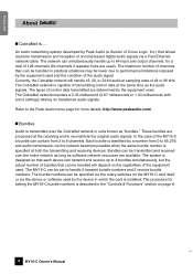
... software used . Currently, the CobraNet network will depend on the MY16-C card itself, or via a Fast Ethernet network cable. Bundles can be handled will handle 16, 20, or 24-bit audio at sampling rates of transmitting control data at the receiving end to 8 bundles simultaneously, but the actual number of bundles that allows real-time transmission and reception of 128 channels...
... software used . Currently, the CobraNet network will depend on the MY16-C card itself, or via a Fast Ethernet network cable. Bundles can be handled will handle 16, 20, or 24-bit audio at sampling rates of transmitting control data at the receiving end to 8 bundles simultaneously, but the actual number of bundles that allows real-time transmission and reception of 128 channels...

MY16-C Owners Manual
Page 6
... and it is recommended that the maximum number of their settings, but only bundles with CobraNet: "multicast" bundles and "unicast" bundles. CobraNet Device C CobraNet Device D Network B CobraNet Device A CobraNet Device Digital Audio Data 3 MY16-C Owner's Manual 5 For this example). Multicast bundles can be used for multicast and unicast bundles: multicast bundles are numbered 1 through 255, while unicast bundles are sent...
... and it is recommended that the maximum number of their settings, but only bundles with CobraNet: "multicast" bundles and "unicast" bundles. CobraNet Device C CobraNet Device D Network B CobraNet Device A CobraNet Device Digital Audio Data 3 MY16-C Owner's Manual 5 For this example). Multicast bundles can be used for multicast and unicast bundles: multicast bundles are numbered 1 through 255, while unicast bundles are sent...

MY16-C Owners Manual
Page 7
... devices receive and are available. Digital audio devices that is automatically assigned and need to 100 meters, while multimode optical fiber cables can result in "repeater" and "switching" configurations. Performer (Receive) C Performer (Receive) D Sync (Word Clock) Network Conductors transmit the synchronization signal that are not connected to another device on the CobraNet network sends the synchronization signal to connect 3 or more devices. In this...
... devices receive and are available. Digital audio devices that is automatically assigned and need to 100 meters, while multimode optical fiber cables can result in "repeater" and "switching" configurations. Performer (Receive) C Performer (Receive) D Sync (Word Clock) Network Conductors transmit the synchronization signal that are not connected to another device on the CobraNet network sends the synchronization signal to connect 3 or more devices. In this...
MY16-C Owners Manual
Page 8
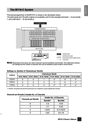
... bit, 48kHz 16 bit, 96kHz 20 bit, 96kHz 24 bit, 96kHz 8 8 7 4*1 4*1 3*1 8 8 8 4*1 4*1 4*1 8 8 8 4*1 4*1 4*1 *1 Number of Channels Bundle1 Bundle2 8 1-8 9-16 7 1-7 9-15 4 1,3,5,7 9,11,13,15 3 1,3,5 9,11,13 MY16-C Owner's Manual 7 5 ENGLISH The MY16-C System The internal signal flow of the MY16-C is shown below . 16 audio inputs and 16 audio outputs are available, and for this example channels 1 ~ 8 are bundle 1, and channels 9 ~ 16 are combined to create single 96-kHz...
... bit, 48kHz 16 bit, 96kHz 20 bit, 96kHz 24 bit, 96kHz 8 8 7 4*1 4*1 3*1 8 8 8 4*1 4*1 4*1 8 8 8 4*1 4*1 4*1 *1 Number of Channels Bundle1 Bundle2 8 1-8 9-16 7 1-7 9-15 4 1,3,5,7 9,11,13,15 3 1,3,5 9,11,13 MY16-C Owner's Manual 7 5 ENGLISH The MY16-C System The internal signal flow of the MY16-C is shown below . 16 audio inputs and 16 audio outputs are available, and for this example channels 1 ~ 8 are bundle 1, and channels 9 ~ 16 are combined to create single 96-kHz...
MY16-C Owners Manual
Page 9
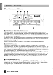
... will light when a network cable is properly connected, and will light when power has been properly applied to the MY16-C card. These indicators will automatically take over. If an error occurs on the PRIMARY circuit (e.g. If an indicator lights or flashes red, try disconnecting it from the corresponding Ethernet connector. In this case please refer the problem to qualified Yamaha service personnel. 4 [IN USE...
... will light when a network cable is properly connected, and will light when power has been properly applied to the MY16-C card. These indicators will automatically take over. If an error occurs on the PRIMARY circuit (e.g. If an indicator lights or flashes red, try disconnecting it from the corresponding Ethernet connector. In this case please refer the problem to qualified Yamaha service personnel. 4 [IN USE...
MY16-C Owners Manual
Page 10
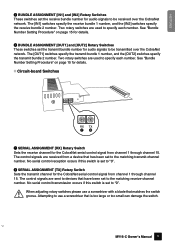
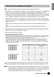
... adjusting rotary switches please use a screwdriver that has been set to the matching transmit-channel number. ENGLISH 5 BUNDLE ASSIGNMENT [IN1] and [IN2] Rotary Switches These switches set the receive bundle number for audio signals to be transmitted over the CobraNet network. Two rotary switches are sent to devices that matches the switch groove. The control signals are used to "0". See "Bundle Number Setting Procedure" on page 15 for details. ■ Circuit-board Switches...
... adjusting rotary switches please use a screwdriver that has been set to the matching transmit-channel number. ENGLISH 5 BUNDLE ASSIGNMENT [IN1] and [IN2] Rotary Switches These switches set the receive bundle number for audio signals to be transmitted over the CobraNet network. Two rotary switches are sent to devices that matches the switch groove. The control signals are used to "0". See "Bundle Number Setting Procedure" on page 15 for details. ■ Circuit-board Switches...
MY16-C Owners Manual
Page 11
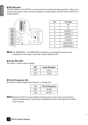
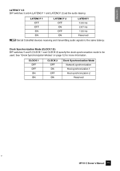
ENGLISH ■ DIP Switches The DIP switches on the MY16-C circuit board can be implemented in the same device to set audio resolution, latency, the clock synchronization mode, and clock frequency. All dip switches are reserved for functions to the same clock frequency. 8 10 MY16-C Owner's Manual Fs OFF ON Clock Frequency 48 kHz 96 kHz n Set all CobraNet devices receiving and transmitting the same audio signals to be used to the...
ENGLISH ■ DIP Switches The DIP switches on the MY16-C circuit board can be implemented in the same device to set audio resolution, latency, the clock synchronization mode, and clock frequency. All dip switches are reserved for functions to the same clock frequency. 8 10 MY16-C Owner's Manual Fs OFF ON Clock Frequency 48 kHz 96 kHz n Set all CobraNet devices receiving and transmitting the same audio signals to be used to the...
MY16-C Owners Manual
Page 12
... ON Clock Synchronization Mode Network synchronization Host synchronization 1 Host synchronization 2 Reserved 9 MY16-C Owner's Manual 11 LATENCY 1 OFF OFF ON ON LATENCY 2 OFF ON OFF ON LATENCY 5.33 ms 2.67 ms 1.33 ms Reserved n Set all CobraNet devices receiving and transmitting audio signals to be used. Clock Synchronization Mode (CLOCK 1/2) DIP switches 5 and 6 (CLOCK 1 and CLOCK 2) specify the clock synchronization mode to the same latency. ENGLISH LATENCY 1/2 DIP switches 3 and...
... ON Clock Synchronization Mode Network synchronization Host synchronization 1 Host synchronization 2 Reserved 9 MY16-C Owner's Manual 11 LATENCY 1 OFF OFF ON ON LATENCY 2 OFF ON OFF ON LATENCY 5.33 ms 2.67 ms 1.33 ms Reserved n Set all CobraNet devices receiving and transmitting audio signals to be used. Clock Synchronization Mode (CLOCK 1/2) DIP switches 5 and 6 (CLOCK 1 and CLOCK 2) specify the clock synchronization mode to the same latency. ENGLISH LATENCY 1/2 DIP switches 3 and...
MY16-C Owners Manual
Page 13
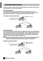
...-network Device Clock MY16-C H1 DME64N/24N, PM5D etc N : Network Synchronization H1 : Host Synchronization 1 Network MY16-C N DME64N/24N, PM5D etc MY16-C N DME64N/24N, PM5D etc 10 12 MY16-C Owner's Manual When the MY16-C is set to feed a clock signal to the MY16-C is the normal synchronization mode. ENGLISH Clock Synchronization Modes The MY16-C provides a selection of host synchronization 1 a. Network Synchronization In this range, and problems with noise or instability...
...-network Device Clock MY16-C H1 DME64N/24N, PM5D etc N : Network Synchronization H1 : Host Synchronization 1 Network MY16-C N DME64N/24N, PM5D etc MY16-C N DME64N/24N, PM5D etc 10 12 MY16-C Owner's Manual When the MY16-C is set to feed a clock signal to the MY16-C is the normal synchronization mode. ENGLISH Clock Synchronization Modes The MY16-C provides a selection of host synchronization 1 a. Network Synchronization In this range, and problems with noise or instability...
MY16-C Owners Manual
Page 14
... etc MY16-C Owner's Manual 13 11 An example of the installed MY16-C cards to Host Synchronization 2. N : Network Synchronization MY16-C N H1 : Host Synchronization 1 DME64N/24N, PM5D etc Network MY16-C H1 DME64N/24N, PM5D etc MY16-C H1 DME64N/24N, PM5D etc Clock Non-network Device Host Synchronization 2 Use this mode if the MY16-C card is to be received from the CobraNet network, set one MY16-C cards are installed in the...
... etc MY16-C Owner's Manual 13 11 An example of the installed MY16-C cards to Host Synchronization 2. N : Network Synchronization MY16-C N H1 : Host Synchronization 1 DME64N/24N, PM5D etc Network MY16-C H1 DME64N/24N, PM5D etc MY16-C H1 DME64N/24N, PM5D etc Clock Non-network Device Host Synchronization 2 Use this mode if the MY16-C card is to be received from the CobraNet network, set one MY16-C cards are installed in the...

MY16-C Owners Manual
Page 15
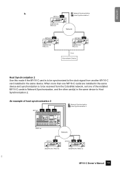
... DME64N/24N, PM5D etc b. An example of all three synchronization modes are combined. a. MY16-C N H2 N : Network Synchronization H1 : Host Synchronization 1 H2 : Host Synchronization 2 DME64N/24N, PM5D etc Network MY16-C H1 H1 MY16-C H1 H1 DME64N/24N, PM5D etc DME64N/24N, PM5D etc Clock Non-network Device 12 14 MY16-C Owner's Manual ENGLISH In some cases, all three synchronization modes used simultaneously.
... DME64N/24N, PM5D etc b. An example of all three synchronization modes are combined. a. MY16-C N H2 N : Network Synchronization H1 : Host Synchronization 1 H2 : Host Synchronization 2 DME64N/24N, PM5D etc Network MY16-C H1 H1 MY16-C H1 H1 DME64N/24N, PM5D etc DME64N/24N, PM5D etc Clock Non-network Device 12 14 MY16-C Owner's Manual ENGLISH In some cases, all three synchronization modes used simultaneously.
MY16-C Owners Manual
Page 16
... device's power is turned off , remove the MY16C card, change the circuit board switch settings, turn power to set a wider range of the right switch to use a screwdriver with a blade that is possible to the host device off before installing the MY16-C. 1 Set the MY16-C circuit-board DIP switches and rotary switches as required. Refer to "A," the corresponding bundle number would be tightened securely. 3 Connect the MY16-C card to set the bundle numbers from the...
... device's power is turned off , remove the MY16C card, change the circuit board switch settings, turn power to set a wider range of the right switch to use a screwdriver with a blade that is possible to the host device off before installing the MY16-C. 1 Set the MY16-C circuit-board DIP switches and rotary switches as required. Refer to "A," the corresponding bundle number would be tightened securely. 3 Connect the MY16-C card to set the bundle numbers from the...

MY16-C Owners Manual
Page 17
... 1234 56 78 NETWORK MID PEAK MASTER SIGNAL IN 1234 56 78 PEAK SIGNAL OUT SCENE NUMBER DME24N MY16-C DME64N Connecting to a Mixer Switching Hub MY16-C DME64N MY16-C YAMAHA Digital Console MY16-C Straight Cable Audio signal and control data EXT. CLOCK 96kHz 88.2kHz 48kHz 44.1kHz 1234 56 78 NETWORK MID PEAK MASTER SIGNAL IN 1234 56 78 PEAK SIGNAL OUT SCENE NUMBER DME24N MY16-C DME64N 16 MY16-C Owner's Manual Switching Hub MY16-C MY16-C DME64N MY16-C 14 CLOCK 96kHz 88.2kHz 48kHz 44.1kHz...
... 1234 56 78 NETWORK MID PEAK MASTER SIGNAL IN 1234 56 78 PEAK SIGNAL OUT SCENE NUMBER DME24N MY16-C DME64N Connecting to a Mixer Switching Hub MY16-C DME64N MY16-C YAMAHA Digital Console MY16-C Straight Cable Audio signal and control data EXT. CLOCK 96kHz 88.2kHz 48kHz 44.1kHz 1234 56 78 NETWORK MID PEAK MASTER SIGNAL IN 1234 56 78 PEAK SIGNAL OUT SCENE NUMBER DME24N MY16-C DME64N 16 MY16-C Owner's Manual Switching Hub MY16-C MY16-C DME64N MY16-C 14 CLOCK 96kHz 88.2kHz 48kHz 44.1kHz...

MY16-C Owners Manual
Page 18
... SIGNAL OUT SCENE NUMBER MY16-C LINK CONDUCT LOCK ERROR NHB32-C DME24N n Not compatible with ACU16-C or NHB32-C control signals. Communication usually occurs over . Redundancy networks offer significantly higher reliability compared to Other CobraNet Devices DME64N MY16-C Audio signal and control data Audio signal and control data ACU16-C Switching Hub EXT. CLOCK 96kHz 88.2kHz 48kHz 44.1kHz 1234 56 78 NETWORK MID PEAK MASTER SIGNAL IN 1234 56 78 PEAK SIGNAL OUT SCENE NUMBER DME24N MY16...
... SIGNAL OUT SCENE NUMBER MY16-C LINK CONDUCT LOCK ERROR NHB32-C DME24N n Not compatible with ACU16-C or NHB32-C control signals. Communication usually occurs over . Redundancy networks offer significantly higher reliability compared to Other CobraNet Devices DME64N MY16-C Audio signal and control data Audio signal and control data ACU16-C Switching Hub EXT. CLOCK 96kHz 88.2kHz 48kHz 44.1kHz 1234 56 78 NETWORK MID PEAK MASTER SIGNAL IN 1234 56 78 PEAK SIGNAL OUT SCENE NUMBER DME24N MY16...
MY16-C Owners Manual
Page 19
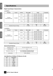
ENGLISH DEUTSCH FRANÇAIS ESPAÑOL Specifications Digital Input/Output Characteristics Terminal Format Latency 5.33ms CobraNet Primary/Secondary CobraNet 2.67ms 1.33ms Data Length 20bit 24bit 20bit 24bit 20bit 24bit Audio 16ch Input / 16ch Output 14ch Input / 14ch Output 16ch Input / 16ch Output 16ch Input / 16ch Output 16ch Input / 16ch Output 16ch Input / 16ch Output Connector RJ45 Sampling Frequency Range Terminal Format Latency 5.33ms CobraNet Primary/Secondary CobraNet 2.67ms 1.33ms Min...
ENGLISH DEUTSCH FRANÇAIS ESPAÑOL Specifications Digital Input/Output Characteristics Terminal Format Latency 5.33ms CobraNet Primary/Secondary CobraNet 2.67ms 1.33ms Data Length 20bit 24bit 20bit 24bit 20bit 24bit Audio 16ch Input / 16ch Output 14ch Input / 14ch Output 16ch Input / 16ch Output 16ch Input / 16ch Output 16ch Input / 16ch Output 16ch Input / 16ch Output Connector RJ45 Sampling Frequency Range Terminal Format Latency 5.33ms CobraNet Primary/Secondary CobraNet 2.67ms 1.33ms Min...

MY16-C Owners Manual
Page 21
Yamaha Manual Library http://www2.yamaha.co.jp/manual/english/ U.R.G., Pro Audio & Digital Musical Instrument Division, Yamaha Corporation © 2004 Yamaha Corporation WC95460 404MWCP3.2-01A0 Printed in JAPAN • This document is printed on chlorine free (ECF) paper with soy ink. • Auf Umweltpapier mit Sojatinte gedruckt. • Ce document a été imprimé sur du papier non blanchi au chlore avec de l'encre d'huile de soja. • Este documento se ha impreso en papel sin cloro alguno, con tinta de soja.
Yamaha Manual Library http://www2.yamaha.co.jp/manual/english/ U.R.G., Pro Audio & Digital Musical Instrument Division, Yamaha Corporation © 2004 Yamaha Corporation WC95460 404MWCP3.2-01A0 Printed in JAPAN • This document is printed on chlorine free (ECF) paper with soy ink. • Auf Umweltpapier mit Sojatinte gedruckt. • Ce document a été imprimé sur du papier non blanchi au chlore avec de l'encre d'huile de soja. • Este documento se ha impreso en papel sin cloro alguno, con tinta de soja.


