
Owner's Manual
Page 4
... the device that used according to the instructions found in to discard electrical and electronic equipment, please contact your national legislation and the Directives 2002/96/EC. See user manual instructions if interference to the terminal which is being affected by YAMAHA CORPORATION OF AMERICA. (FCC DoC) IMPORTANT NOTICE FOR THE UNITED KINGDOM Connecting the Plug and Cord WARNING: THIS...
... the device that used according to the instructions found in to discard electrical and electronic equipment, please contact your national legislation and the Directives 2002/96/EC. See user manual instructions if interference to the terminal which is being affected by YAMAHA CORPORATION OF AMERICA. (FCC DoC) IMPORTANT NOTICE FOR THE UNITED KINGDOM Connecting the Plug and Cord WARNING: THIS...
Owner's Manual
Page 5
...; Use only the supplied power cord/plug. Even when the power switch is easily accessible. Connections • Before connecting the device to you purchased, the included power cord may result in other hazards. Before turning the power on , trip over, or roll anything over it might spill into the device, turn off , electricity is printed on page 35. MG20XU/MG20/MG16XU/MG16/MG12XU/MG12 Owner's Manual 5 If...
...; Use only the supplied power cord/plug. Even when the power switch is easily accessible. Connections • Before connecting the device to you purchased, the included power cord may result in other hazards. Before turning the power on , trip over, or roll anything over it might spill into the device, turn off , electricity is printed on page 35. MG20XU/MG20/MG16XU/MG16/MG12XU/MG12 Owner's Manual 5 If...
Owner's Manual
Page 6
...manual as in direct sunlight, near a heater, or in a car during the day), in order to prevent the possibility of panel disfiguration, unstable operation, or damage to the internal components. • Do not place vinyl, plastic or rubber objects on or near the name plate, which is at a high or uncomfortable volume level...may cause problems with electrical contact or fader motion. • When turning on the AC power in your audio system, always turn on the buttons, switches or connectors. • Do not use speakers or headphones for damage caused by qualified Yamaha service personnel....
...manual as in direct sunlight, near a heater, or in a car during the day), in order to prevent the possibility of panel disfiguration, unstable operation, or damage to the internal components. • Do not place vinyl, plastic or rubber objects on or near the name plate, which is at a high or uncomfortable volume level...may cause problems with electrical contact or fader motion. • When turning on the AC power in your audio system, always turn on the buttons, switches or connectors. • Do not use speakers or headphones for damage caused by qualified Yamaha service personnel....
Owner's Manual
Page 7
... Panel 14 Rear Panel 15 Input Channel Block 16 Built-in Effects Block (XU Models Only) .........22 Master Block 24 Power Block 27 USB Block (XU Models Only 28 Troubleshooting 29 When No Sound Is Output 29 Other 31 Appendix 32 General Specifications 32 Effect Programs 33 Jack and Connector List 34 Connector Types 34 Rack Mounting 35 Index 36 MG20XU/MG20/MG16XU/MG16/MG12XU/MG12 Owner's Manual 7 Contents Precautions 5 Contents 7 Main Features 8 Quick Start Guide 9 Step 1 Preparing the Power Supply 9 Step 2 Making Connections 9 Step 3 Powering...
... Panel 14 Rear Panel 15 Input Channel Block 16 Built-in Effects Block (XU Models Only) .........22 Master Block 24 Power Block 27 USB Block (XU Models Only 28 Troubleshooting 29 When No Sound Is Output 29 Other 31 Appendix 32 General Specifications 32 Effect Programs 33 Jack and Connector List 34 Connector Types 34 Rack Mounting 35 Index 36 MG20XU/MG20/MG16XU/MG16/MG12XU/MG12 Owner's Manual 7 Contents Precautions 5 Contents 7 Main Features 8 Quick Start Guide 9 Step 1 Preparing the Power Supply 9 Step 2 Making Connections 9 Step 3 Powering...
Owner's Manual
Page 8
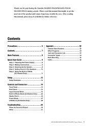
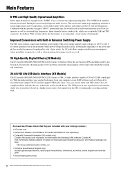
... line level input, to record the mixer output. http://www.yamahaproaudio.com/mg_xu/ • Technical Specifications (English only): Includes general specifications, input/output characteristics, dimensions, as well as Cubase AI to accommodate a wide variety of the sound with a faster attack. The USB protocol uses asynchronous data transfer. Input channels feature combo jacks, which can use DAW software such as a block diagram and level diagram. • Owner's Manual (this book) 8 MG20XU/MG20/MG16XU/MG16/MG12XU/MG12 Owner's Manual Improved Convenience with "D-PRE...
... line level input, to record the mixer output. http://www.yamahaproaudio.com/mg_xu/ • Technical Specifications (English only): Includes general specifications, input/output characteristics, dimensions, as well as Cubase AI to accommodate a wide variety of the sound with a faster attack. The USB protocol uses asynchronous data transfer. Input channels feature combo jacks, which can use DAW software such as a block diagram and level diagram. • Owner's Manual (this book) 8 MG20XU/MG20/MG16XU/MG16/MG12XU/MG12 Owner's Manual Improved Convenience with "D-PRE...
Owner's Manual
Page 9
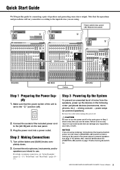
... every time you are using . • Power switch (rear panel) • [AC IN] jack (rear panel) [GAIN] knobs MG20XU MG16XU Faders MG12XU Step 1 Preparing the Power Supply 1. Also, read the details about the [PHANTOM +48V] switch on page 17 before turning on the power to turn the mixer's [PHANTOM +48V] switch on before turning the switch on /off in the order given in the following order: peripheral devices (instruments, microphones, etc.) mixing console power amps (or powered speakers). CAUTION...
... every time you are using . • Power switch (rear panel) • [AC IN] jack (rear panel) [GAIN] knobs MG20XU MG16XU Faders MG12XU Step 1 Preparing the Power Supply 1. Also, read the details about the [PHANTOM +48V] switch on page 17 before turning on the power to turn the mixer's [PHANTOM +48V] switch on before turning the switch on /off in the order given in the following order: peripheral devices (instruments, microphones, etc.) mixing console power amps (or powered speakers). CAUTION...
Owner's Manual
Page 10
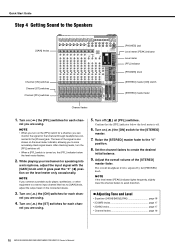
...are using. Quick Start Guide Step 4 Getting Sound to more accurately check signal levels. The level of the signal is turned on the level meter indicator, allowing you turn the [PFL] switches off. • When a [PFL] switch is also shown on , the [PFL] indicator below the level meter flashes. 2. NOTE • When you to the Speakers [GAIN] knobs Channel [ON] switches Channel [ST] switches Channel [PFL] switches [PHONES] jack Level meter [PEAK] indicator Level meter [PFL] indicator [PHONES] knob [STEREO] master [ON] switch [STEREO] master fader Channel faders 1. While playing...
...are using. Quick Start Guide Step 4 Getting Sound to more accurately check signal levels. The level of the signal is turned on the level meter indicator, allowing you turn the [PFL] switches off. • When a [PFL] switch is also shown on , the [PFL] indicator below the level meter flashes. 2. NOTE • When you to the Speakers [GAIN] knobs Channel [ON] switches Channel [ST] switches Channel [PFL] switches [PHONES] jack Level meter [PEAK] indicator Level meter [PFL] indicator [PHONES] knob [STEREO] master [ON] switch [STEREO] master fader Channel faders 1. While playing...

Owner's Manual
Page 12
... music playback and/or recording) (The [USB 2.0] jack is on the rear panel. Rear Panel Computer (for musician monitoring) Microphones 3 Bass guitar Electric acoustic guitar DI Microphones 2 Synthesizer Powered speakers (main) Mono input jacks accept both XLR connectors and phone connectors. Foot switch (YAMAHA FC5) (The [FOOT SW] jack is on XU models only.) NOTE On the MG20XU/MG20, the [SEND] jack, [GROUP OUT] jack, [MONITOR OUT], jack, and [STEREO OUT] jack are located on XU models only.) Portable audio player Headphones...
... music playback and/or recording) (The [USB 2.0] jack is on the rear panel. Rear Panel Computer (for musician monitoring) Microphones 3 Bass guitar Electric acoustic guitar DI Microphones 2 Synthesizer Powered speakers (main) Mono input jacks accept both XLR connectors and phone connectors. Foot switch (YAMAHA FC5) (The [FOOT SW] jack is on XU models only.) NOTE On the MG20XU/MG20, the [SEND] jack, [GROUP OUT] jack, [MONITOR OUT], jack, and [STEREO OUT] jack are located on XU models only.) Portable audio player Headphones...

Owner's Manual
Page 14
... master block jacks on the MG20XU/MG20 are all located on the rear panel, except the [PHONES] jack. [MONITOR] section (page 25) [SEND MASTER] section (page 26) [STEREO] section (page 27) [GROUP] section (page 26) Input Channel Block (page 16 - 21) Built-in Effects Block (XU models only) (page 22 - 23) Master Block (page 24 - 27) 14 MG20XU/MG20/MG16XU/MG16/MG12XU/MG12 Owner's Manual Controls and Connectors Front Panel The number and locations of jacks and controls...
... master block jacks on the MG20XU/MG20 are all located on the rear panel, except the [PHONES] jack. [MONITOR] section (page 25) [SEND MASTER] section (page 26) [STEREO] section (page 27) [GROUP] section (page 26) Input Channel Block (page 16 - 21) Built-in Effects Block (XU models only) (page 22 - 23) Master Block (page 24 - 27) 14 MG20XU/MG20/MG16XU/MG16/MG12XU/MG12 Owner's Manual Controls and Connectors Front Panel The number and locations of jacks and controls...
Owner's Manual
Page 17
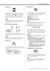
...} between the [LINE] stereo input jack and the [USB 2.0] jack. o [LINE /USB ] switch (XU models) Switches the audio source input on when using one or more phantom-powered condenser microphones. NOTE The volume input from computers through [USB 2.0] jack can be some noise when operating switches. The indicator lights when this switch is as the [STEREO] master fader and the [GROUP] fader to their minimum levels before operating other device with a low input level to the channel. NOTICE • Be sure to leave this switch off . Set output controls such as...
...} between the [LINE] stereo input jack and the [USB 2.0] jack. o [LINE /USB ] switch (XU models) Switches the audio source input on when using one or more phantom-powered condenser microphones. NOTE The volume input from computers through [USB 2.0] jack can be some noise when operating switches. The indicator lights when this switch is as the [STEREO] master fader and the [GROUP] fader to their minimum levels before operating other device with a low input level to the channel. NOTICE • Be sure to leave this switch off . Set output controls such as...
Owner's Manual
Page 18
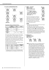
... amplifies (boosts) the corresponding frequency band, while turning it to the GROUP 2 or GROUP 4 bus only. 18 MG20XU/MG20/MG16XU/MG16/MG12XU/MG12 Owner's Manual When the knob is set to the 12 o'clock position, the same volume is sent to the AUX bus by the [PRE] switch. • The [AUX4/FX] and [AUX2/FX] knobs are used to select whether the pre-fader ( ) (the signal before fader adjustment) or post fader...
... amplifies (boosts) the corresponding frequency band, while turning it to the GROUP 2 or GROUP 4 bus only. 18 MG20XU/MG20/MG16XU/MG16/MG12XU/MG12 Owner's Manual When the knob is set to the 12 o'clock position, the same volume is sent to the AUX bus by the [PRE] switch. • The [AUX4/FX] and [AUX2/FX] knobs are used to select whether the pre-fader ( ) (the signal before fader adjustment) or post fader...

Owner's Manual
Page 19
BAL LINE L LINE R STEREO L bus, GROUP 1 bus, GROUP 3 bus STEREO R bus, GROUP 2 bus, GROUP 4 bus • PAN/BAL: This knob performs both the [LINE] (L) and [LINE] (R) jacks. !3 [ON] switches Turn this condition, the audio from each channel's signal is sent. You can use this as a [PAN] control when sound is input to the [LINE] (L/MONO) jack, and as a [BAL] control when sound is input to both [PAN] and [BAL] functions. REO L/R buses. In this switch on ( ) to output the signal to the corresponding buses. • [1-2] switch: Assigns the channel's signal to...
BAL LINE L LINE R STEREO L bus, GROUP 1 bus, GROUP 3 bus STEREO R bus, GROUP 2 bus, GROUP 4 bus • PAN/BAL: This knob performs both the [LINE] (L) and [LINE] (R) jacks. !3 [ON] switches Turn this condition, the audio from each channel's signal is sent. You can use this as a [PAN] control when sound is input to the [LINE] (L/MONO) jack, and as a [BAL] control when sound is input to both [PAN] and [BAL] functions. REO L/R buses. In this switch on ( ) to output the signal to the corresponding buses. • [1-2] switch: Assigns the channel's signal to...
Owner's Manual
Page 25
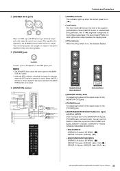
...buses: [STEREO] ( ) GROUP 1-2 buses: [GROUP] ( ), [1-2] ( ) GROUP 3-4 buses: [GROUP] ( ), [3-4] ( ) MG20XU/MG20/MG16XU/MG16/MG12XU/MG12 Owner's Manual 25 The "0" (< ) segment corresponds to the [MONITOR OUT] jack, [PHONES] jack, and level meter. t [PHONES] jack Controls and Connectors • [POWER] indicator This indicator lights up when the mixer's power is output. The signal level is adjusted by the [STEREO] master fader before it is on ( ). • Level meter The level meter LED shows the level of headphones to this switch to the power amplifier driving your main speakers...
...buses: [STEREO] ( ) GROUP 1-2 buses: [GROUP] ( ), [1-2] ( ) GROUP 3-4 buses: [GROUP] ( ), [3-4] ( ) MG20XU/MG20/MG16XU/MG16/MG12XU/MG12 Owner's Manual 25 The "0" (< ) segment corresponds to the [MONITOR OUT] jack, [PHONES] jack, and level meter. t [PHONES] jack Controls and Connectors • [POWER] indicator This indicator lights up when the mixer's power is output. The signal level is adjusted by the [STEREO] master fader before it is on ( ). • Level meter The level meter LED shows the level of headphones to this switch to the power amplifier driving your main speakers...

Owner's Manual
Page 27
.../MG12 Owner's Manual 27 The switch lights when on ( ) to enable the [STEREO] master fader. If you do not plan to use the mixer for at least 6 seconds before turning it into an AC outlet. • [ON] switch Turn this switch on . • [STEREO] master fader For adjusting the level of the signal output to the [STEREO OUT] jack. o [STEREO] section STEREO L STEREO R USB-REC-L USB-REC-R STEREO STL MONI STR MONI ON Controls and Connectors Power Block • [ / ] POWER switch STEREO OUT L [+4dBu] STEREO...
.../MG12 Owner's Manual 27 The switch lights when on ( ) to enable the [STEREO] master fader. If you do not plan to use the mixer for at least 6 seconds before turning it into an AC outlet. • [ON] switch Turn this switch on . • [STEREO] master fader For adjusting the level of the signal output to the [STEREO OUT] jack. o [STEREO] section STEREO L STEREO R USB-REC-L USB-REC-R STEREO STL MONI STR MONI ON Controls and Connectors Power Block • [ / ] POWER switch STEREO OUT L [+4dBu] STEREO...
Owner's Manual
Page 28
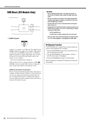
... between turning the mixer on while DAW software is being sent from the mixer. • Allow at the lower right of the display. 28 MG20XU/MG20/MG16XU/MG16/MG12XU/MG12 Owner's Manual Controls and Connectors USB Block (XU Models Only) only MG20XU/MG16XU/MG12XU USB-REC-L USB-REC-R USB Audio Controller USB-Att. • [USB 2.0] jack (USB-Att.) USB-PLAY-L USB-PLAY-R NOTICE • Use an A/B type USB cable. The cable should be used to adjust the volume of a channel which has a [LINE / USB ] switch is on...
... between turning the mixer on while DAW software is being sent from the mixer. • Allow at the lower right of the display. 28 MG20XU/MG20/MG16XU/MG16/MG12XU/MG12 Owner's Manual Controls and Connectors USB Block (XU Models Only) only MG20XU/MG16XU/MG12XU USB-REC-L USB-REC-R USB Audio Controller USB-Att. • [USB 2.0] jack (USB-Att.) USB-PLAY-L USB-PLAY-R NOTICE • Use an A/B type USB cable. The cable should be used to adjust the volume of a channel which has a [LINE / USB ] switch is on...
Owner's Manual
Page 30
.... Channel faders For adjusting the level for each channel. [STEREO] master fader For adjusting the overall volume, with "0" as the nominal level. [PHONES] knob For adjusting the headphone level. [SOURCE]/[SOURCE SELECT] (Monitor signal selection switch) Use to monitor the sound via the level meter and/or headphones. • MG12XU/MG12 STEREO L/R buses: [STEREO] ( ) GROUP 1-2 buses: [GROUP] ( ) • MG20XU/MG20/MG16XU/MG16 STEREO L/R buses: [STEREO] ( ) GROUP 1-2 buses: [GROUP] ( ), [1-2] ( ) GROUP 3-4 buses: [GROUP] ( ), [3-4] ( ) To monitor the signal of noise from the speakers, turn...
.... Channel faders For adjusting the level for each channel. [STEREO] master fader For adjusting the overall volume, with "0" as the nominal level. [PHONES] knob For adjusting the headphone level. [SOURCE]/[SOURCE SELECT] (Monitor signal selection switch) Use to monitor the sound via the level meter and/or headphones. • MG12XU/MG12 STEREO L/R buses: [STEREO] ( ) GROUP 1-2 buses: [GROUP] ( ) • MG20XU/MG20/MG16XU/MG16 STEREO L/R buses: [STEREO] ( ) GROUP 1-2 buses: [GROUP] ( ), [1-2] ( ) GROUP 3-4 buses: [GROUP] ( ), [3-4] ( ) To monitor the signal of noise from the speakers, turn...
Owner's Manual
Page 31
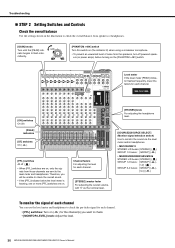
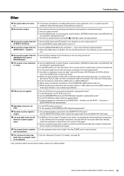
.../MG12 Owner's Manual 31 Check that the power of that is the source of audio play- Turn this switch off . The sound is low, distorted, or noisy. Are the [GAIN] knobs for each channel, channel faders, [STEREO] master fader, and [GROUP] faders adjusted to appropriate levels? Is the [PAD] switch on ? No sound is off, are the [ON] switches for the channels you are not using a condenser microphone, is the [PHANTOM +48V] switch turned on...
.../MG12 Owner's Manual 31 Check that the power of that is the source of audio play- Turn this switch off . The sound is low, distorted, or noisy. Are the [GAIN] knobs for each channel, channel faders, [STEREO] master fader, and [GROUP] faders adjusted to appropriate levels? Is the [PAD] switch on ? No sound is off, are the [ON] switches for the channels you are not using a condenser microphone, is the [PHANTOM +48V] switch turned on...
Owner's Manual
Page 32
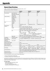
Input channels Output channels Bus Input Channel Function Mono: MIC/LINE Mono/Stereo: MIC/LINE Stereo: LINE STEREO OUT MONITOR OUT PHONES AUX SEND GROUP OUT STEREO GROUP AUX PAD HPF COMP EQ PEAK LED Level Meter Pre Monitor LEVEL Built-in every locale, please check with 1 kHz band pass filter. reserves the right to change or modify products or specifications at any time without prior notice. European Models Inrush Current based on EN 55103-1:2009 3.0 A (on initial switch-on /off) USB Audio Class 2.0 compliant, Sampling Frequency: Max 192...
Input channels Output channels Bus Input Channel Function Mono: MIC/LINE Mono/Stereo: MIC/LINE Stereo: LINE STEREO OUT MONITOR OUT PHONES AUX SEND GROUP OUT STEREO GROUP AUX PAD HPF COMP EQ PEAK LED Level Meter Pre Monitor LEVEL Built-in every locale, please check with 1 kHz band pass filter. reserves the right to change or modify products or specifications at any time without prior notice. European Models Inrush Current based on EN 55103-1:2009 3.0 A (on initial switch-on /off) USB Audio Class 2.0 compliant, Sampling Frequency: Max 192...
Owner's Manual
Page 36
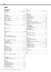
... 18 Bus assign switch 19, 23 C [COMP] knob 17 D DI (direct box 29 D-PRE 8 E Effect program list 22 Equalizer ([HIGH]/[MID]/[LOW 18 F [FOOT SW] (Foot Switch) jack 23 [FX ON] switch 23 [FX RTN] fader 23 [FX RTN LEVEL] knob 23 G [GAIN] knob 17 [GROUP] section 26 [GROUP 1-2] fader 26 [GROUP 3-4] fader 26 [GROUP OUT] jack 24 H [HPF] (High Pass Filter) switch 17 L Level meter 25 [LINE /USB ] switch 17 M [MIC/LINE 16 [MONITOR] section 25 [MONITOR LEVEL] knob 25 [MONITOR OUT] jack 24 Mono input jack 16 Mono/stereo input jack...
... 18 Bus assign switch 19, 23 C [COMP] knob 17 D DI (direct box 29 D-PRE 8 E Effect program list 22 Equalizer ([HIGH]/[MID]/[LOW 18 F [FOOT SW] (Foot Switch) jack 23 [FX ON] switch 23 [FX RTN] fader 23 [FX RTN LEVEL] knob 23 G [GAIN] knob 17 [GROUP] section 26 [GROUP 1-2] fader 26 [GROUP 3-4] fader 26 [GROUP OUT] jack 24 H [HPF] (High Pass Filter) switch 17 L Level meter 25 [LINE /USB ] switch 17 M [MIC/LINE 16 [MONITOR] section 25 [MONITOR LEVEL] knob 25 [MONITOR OUT] jack 24 Mono input jack 16 Mono/stereo input jack...
Technical Specifications
Page 1
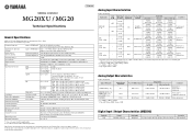
... dBu (1 kHz), GAIN knob: Min -128 dBu (Mono Input Channel, Rs: 150 Ω, GAIN knob: Max) -102 dBu (STEREO OUT, STEREO master fader: Min) -78 dB 20 channels: Mono [MIC/LINE]: 12, Mono/Stereo [MIC/LINE]: 2, Stereo [LINE]: 2 STEREO OUT: 2, PHONES: 1, MONITOR OUT: 1, AUX SEND: 4, GROUP OUT: 4 STEREO: 1, GROUP: 4, AUX: 4 (MG20XU: incl. Frequency Response Total Harmonic Distortion (THD+N) Hum & Noise *1 (20 Hz to 20 kHz) Crosstalk(1 kHz) *2 Input channels Output channels Bus Input Channel Function Level Meter Built-in every locale, please check with 1 kHz band pass filter. CH 19...
... dBu (1 kHz), GAIN knob: Min -128 dBu (Mono Input Channel, Rs: 150 Ω, GAIN knob: Max) -102 dBu (STEREO OUT, STEREO master fader: Min) -78 dB 20 channels: Mono [MIC/LINE]: 12, Mono/Stereo [MIC/LINE]: 2, Stereo [LINE]: 2 STEREO OUT: 2, PHONES: 1, MONITOR OUT: 1, AUX SEND: 4, GROUP OUT: 4 STEREO: 1, GROUP: 4, AUX: 4 (MG20XU: incl. Frequency Response Total Harmonic Distortion (THD+N) Hum & Noise *1 (20 Hz to 20 kHz) Crosstalk(1 kHz) *2 Input channels Output channels Bus Input Channel Function Level Meter Built-in every locale, please check with 1 kHz band pass filter. CH 19...


