Owner's Manual
Page 2
... case of the three pin plug. * This applies only to products distributed by Yamaha may cause interference harmful to use the product. 2. Failure to follow instructions could void your authority, granted by YAMAHA CORPORATION OF AMERICA, not the MG206C/MG166C. (class B) 2 MG206C/MG166CX/MG166C Owner's Manual If you can be connected to the terminal which is connected to the earth terminal...
... case of the three pin plug. * This applies only to products distributed by Yamaha may cause interference harmful to use the product. 2. Failure to follow instructions could void your authority, granted by YAMAHA CORPORATION OF AMERICA, not the MG206C/MG166C. (class B) 2 MG206C/MG166CX/MG166C Owner's Manual If you can be connected to the terminal which is connected to the earth terminal...
Owner's Manual
Page 3
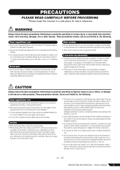
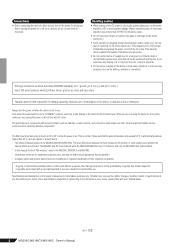
... follow the basic precautions listed below to , the following : Power supply/Power cord • Remove the electric plug from the outlet when the device is easily accessible. These precautions include, but are using the product for extended periods of time, or during use of panel disfiguration or damage to the product all equalizer controls and faders to the device or...
... follow the basic precautions listed below to , the following : Power supply/Power cord • Remove the electric plug from the outlet when the device is easily accessible. These precautions include, but are using the product for extended periods of time, or during use of panel disfiguration or damage to the product all equalizer controls and faders to the device or...
Owner's Manual
Page 4
... Owner's Manual applies to change or modify products or specifications at the minimum level. The main differences between the three models are the number of input channels and whether the internal effects are wired as 15 to the device at any hearing loss or ringing in ambient temperatures higher than personal use excessive force on the AC power in doubt about replacing...
... Owner's Manual applies to change or modify products or specifications at the minimum level. The main differences between the three models are the number of input channels and whether the internal effects are wired as 15 to the device at any hearing loss or ringing in ambient temperatures higher than personal use excessive force on the AC power in doubt about replacing...
Owner's Manual
Page 5
... 10 The Modulation Effects: Phasing, Chorus, and Flanging 10 Compression 10 ■ Reference 11 Setup 11 Front & Rear Panels 12 Channel Control Section 12 Digital Effects 15 Master Control Section 16 Digital Effect Program List (Only MG166CX).19 Jack List 19 Troubleshooting 20 Specifications 75 Accessories • Owner's Manual • AC power adaptor (PA-30)* * May not be sure to unplug the adaptor from the outlet when not using the mixer, or when there...
... 10 The Modulation Effects: Phasing, Chorus, and Flanging 10 Compression 10 ■ Reference 11 Setup 11 Front & Rear Panels 12 Channel Control Section 12 Digital Effects 15 Master Control Section 16 Digital Effect Program List (Only MG166CX).19 Jack List 19 Troubleshooting 20 Specifications 75 Accessories • Owner's Manual • AC power adaptor (PA-30)* * May not be sure to unplug the adaptor from the outlet when not using the mixer, or when there...
Owner's Manual
Page 6
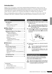
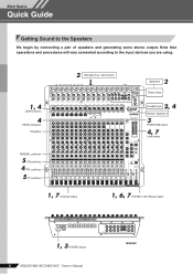
Note that operations and procedures will vary somewhat according to the Speakers We begin by connecting a pair of speakers and generating some stereo output. Mixer Basics Quick Guide Mixer Basics Getting Sound to the input devices you are using. 1, 4 GAIN controls 4 PEAK indicators Equalizer 2 Microphones, instruments 2 Speakers Power Amp 2, 4 Headphones Monitor Speakers 3 PHANTOM switch 4, 7 Level meter PAN/BAL switches 5 ON switches 4 PFL switches 5 ST switches 1, 7 Channel faders 1, 6, 7 STEREO OUT Master fader 1, 3 POWER switch 6 MG206C/MG166CX/MG166C Owner's Manual MG206C
Note that operations and procedures will vary somewhat according to the Speakers We begin by connecting a pair of speakers and generating some stereo output. Mixer Basics Quick Guide Mixer Basics Getting Sound to the input devices you are using. 1, 4 GAIN controls 4 PEAK indicators Equalizer 2 Microphones, instruments 2 Speakers Power Amp 2, 4 Headphones Monitor Speakers 3 PHANTOM switch 4, 7 Level meter PAN/BAL switches 5 ON switches 4 PFL switches 5 ST switches 1, 7 Channel faders 1, 6, 7 STEREO OUT Master fader 1, 3 POWER switch 6 MG206C/MG166CX/MG166C Owner's Manual MG206C
Owner's Manual
Page 7
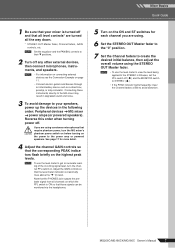
... level meter to create the desired initial balance, then adjust the overall volume using . 6 Set the STEREO OUT Master fader to the "0" position. 7 Set the Channel faders to get an accurate reading of the incoming signal level, turn the MG mixer's phantom power switch on before turning on page 11. • Connect electric guitars and basses through an intermediary device such as a direct box, preamp, or amp simulator. Mixer Basics Quick Guide 1 Be sure that your speakers, power...
... level meter to create the desired initial balance, then adjust the overall volume using . 6 Set the STEREO OUT Master fader to the "0" position. 7 Set the Channel faders to get an accurate reading of the incoming signal level, turn the MG mixer's phantom power switch on before turning on page 11. • Connect electric guitars and basses through an intermediary device such as a direct box, preamp, or amp simulator. Mixer Basics Quick Guide 1 Be sure that your speakers, power...
Owner's Manual
Page 8
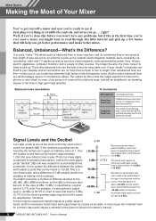
... will be heard is 120 dB. Balanced noise cancellation Noise Phase inversion Hot (+) Cold (-) Ground Source Cable Phase inversion Noise cancelled Receiving device Noise-free signal To summarize Microphones Use balanced lines. If the smallest sound that can be amplified by power lines, motors, electric appliances, computer monitors, and a variety of other types of equipment have inputs and outputs with for practical calculations, and so the...
... will be heard is 120 dB. Balanced noise cancellation Noise Phase inversion Hot (+) Cold (-) Ground Source Cable Phase inversion Noise cancelled Receiving device Noise-free signal To summarize Microphones Use balanced lines. If the smallest sound that can be amplified by power lines, motors, electric appliances, computer monitors, and a variety of other types of equipment have inputs and outputs with for practical calculations, and so the...
Owner's Manual
Page 10
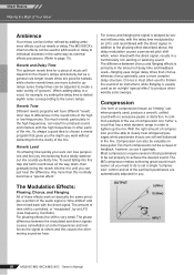
... effect" to differences in the mix. OUTPUT (Min) (Max) INPUT 10 MG206C/MG166CX/MG166C Owner's Manual Reverb Tone Different reverb programs will depend on the music's tempo and density, but as reverb or delay. The Modulation Effects: Phasing, Chorus, and Flanging All of these effects work on basically the same principle: a portion of the mix. Chorus is most often used to thicken the sound of an instrument, while flanging is set...
... effect" to differences in the mix. OUTPUT (Min) (Max) INPUT 10 MG206C/MG166CX/MG166C Owner's Manual Reverb Tone Different reverb programs will depend on the music's tempo and density, but as reverb or delay. The Modulation Effects: Phasing, Chorus, and Flanging All of these effects work on basically the same principle: a portion of the mix. Chorus is most often used to thicken the sound of an instrument, while flanging is set...
Owner's Manual
Page 13
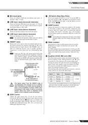
... Front & Rear Panels 1 MIC Input jacks These are balanced XLR-type microphone input jacks. (1: Ground; 2: Hot; 3: Cold) 2 LINE Input Jacks (monaural channels) These are attenuated while the overall level is the LINE input adjustment range. 7 Switch (High-Pass Filter) This switch toggles the HPF on or off. As the knob is turned to an effect unit, but please be used at response in degraded sound quality or even complete sound cancellation. 6 GAIN Control Adjusts the input signal level. sleeve = ground...
... Front & Rear Panels 1 MIC Input jacks These are balanced XLR-type microphone input jacks. (1: Ground; 2: Hot; 3: Cold) 2 LINE Input Jacks (monaural channels) These are attenuated while the overall level is the LINE input adjustment range. 7 Switch (High-Pass Filter) This switch toggles the HPF on or off. As the knob is turned to an effect unit, but please be used at response in degraded sound quality or even complete sound cancellation. 6 GAIN Control Adjusts the input signal level. sleeve = ground...
Owner's Manual
Page 14
... channel fader (post-fader signal) to minimize noise. 14 MG206C/MG166CX/MG166C Owner's Manual signals input to the R input (even channel) go to the GROUP 1 or 3 buses or to the STEREO L bus; NOTE On channels where this switch on the STEREO L/R bus. D ON Switch Turn this knob provides both PAN and BAL control, the knob operates as a PAN control when input is received via both L and R inputs. NOTE To send the signal to the GROUP 1/2 bus turn the ON switch on each mixer model...
... channel fader (post-fader signal) to minimize noise. 14 MG206C/MG166CX/MG166C Owner's Manual signals input to the R input (even channel) go to the GROUP 1 or 3 buses or to the STEREO L bus; NOTE On channels where this switch on the STEREO L/R bus. D ON Switch Turn this knob provides both PAN and BAL control, the knob operates as a PAN control when input is received via both L and R inputs. NOTE To send the signal to the GROUP 1/2 bus turn the ON switch on each mixer model...
Owner's Manual
Page 15
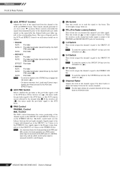
... effect. The switch lights orange when on . The internal effect is applied only if this switch is turned on . These parameter values are reset when the power is not affected by the EFFECT RTN fader. 5 ON Switch Switches the internal effect on to send the effect signal to the PFL bus. 7 1-2 Switch This switch assigns the effect signal to the GROUP 1/2 bus. 8 3-4 Switch This switch assigns the effect signal to the GROUP 3/4 bus. 9 ST Switch This switch assigns the effect signal to the STEREO L/R bus. 0 EFFECT RTN Fader Adjusts the signal level sent from the internal digital...
... effect. The switch lights orange when on . The internal effect is applied only if this switch is turned on . These parameter values are reset when the power is not affected by the EFFECT RTN fader. 5 ON Switch Switches the internal effect on to send the effect signal to the PFL bus. 7 1-2 Switch This switch assigns the effect signal to the GROUP 1/2 bus. 8 3-4 Switch This switch assigns the effect signal to the GROUP 3/4 bus. 9 ST Switch This switch assigns the effect signal to the STEREO L/R bus. 0 EFFECT RTN Fader Adjusts the signal level sent from the internal digital...
Owner's Manual
Page 17
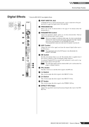
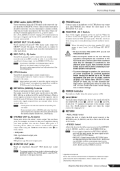
... used to the phantom power supply. NOTE • If you wish to record mixer's stereo output while using one or more phantom-powered condenser microphones. NOTE The signal output by these jacks can be sent to the STEREO L/R bus as well as the MONITOR OUT jacks. 9 PHANTOM +48 V Switch This switch toggles phantom power on the input channels. 8 PHONES Jack Connect a pair of the signal is returned a mono mix of headphones to the power amplifier driving your main speakers. MG206C/MG166CX/MG166C Owner's Manual 17 When a stereo signal...
... used to the phantom power supply. NOTE • If you wish to record mixer's stereo output while using one or more phantom-powered condenser microphones. NOTE The signal output by these jacks can be sent to the STEREO L/R bus as well as the MONITOR OUT jacks. 9 PHANTOM +48 V Switch This switch toggles phantom power on the input channels. 8 PHONES Jack Connect a pair of the signal is returned a mono mix of headphones to the power amplifier driving your main speakers. MG206C/MG166CX/MG166C Owner's Manual 17 When a stereo signal...
Owner's Manual
Page 18
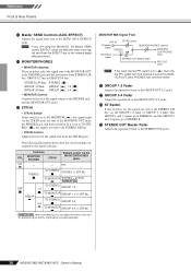
... signal level to the SEND (AUX, EFFECT) jacks. Reference Front & Rear Panels C Master SEND Controls (AUX, EFFECT) Adjusts the signal level sent to the GROUP OUT 3/ 4 jacks. Switches PFL MONITOR/ PHONES 2TR IN ON - - MONITOR MIX Signal Flow 2TR IN 2TR IN control Playback signal Recording STEREO bus MONITOR/PHONES controls MONITOR OUT/PHONES jacks signal STEREO OUT Master fader REC OUT jacks NOTE If the input channel PFL switch is sent to the PHONES jack and the MONITOR OUT jacks. If it is set to the MONITOR OUT jacks, the PHONES jack, and the level meter...
... signal level to the SEND (AUX, EFFECT) jacks. Reference Front & Rear Panels C Master SEND Controls (AUX, EFFECT) Adjusts the signal level sent to the GROUP OUT 3/ 4 jacks. Switches PFL MONITOR/ PHONES 2TR IN ON - - MONITOR MIX Signal Flow 2TR IN 2TR IN control Playback signal Recording STEREO bus MONITOR/PHONES controls MONITOR OUT/PHONES jacks signal STEREO OUT Master fader REC OUT jacks NOTE If the input channel PFL switch is sent to the PHONES jack and the MONITOR OUT jacks. If it is set to the MONITOR OUT jacks, the PHONES jack, and the level meter...
Owner's Manual
Page 19
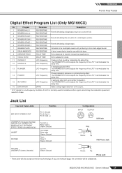
Echo suitable for karaoke (sing-along) applications. A short reverb that is normally used to phone plugs. A wah-wah effect with kick drum. An LFO is ideal for Low Frequency Oscillator. Jack List Input and Output Jacks Polarities MIC INPUT, STEREO OUT Pin 1: Ground Pin 2: Hot (+) Pin 3: Cold (-) LINE INPUT (monaural channels) GROUP OUT, STEREO OUT, MONITOR OUT, AUX SEND, EFFECT SEND (Only MG166CX)* INSERT PHONES Tip: Hot (+) Ring: Cold (-) Sleeve: Ground Tip: Output Ring: Input Sleeve: Ground Tip...
Echo suitable for karaoke (sing-along) applications. A short reverb that is normally used to phone plugs. A wah-wah effect with kick drum. An LFO is ideal for Low Frequency Oscillator. Jack List Input and Output Jacks Polarities MIC INPUT, STEREO OUT Pin 1: Ground Pin 2: Hot (+) Pin 3: Cold (-) LINE INPUT (monaural channels) GROUP OUT, STEREO OUT, MONITOR OUT, AUX SEND, EFFECT SEND (Only MG166CX)* INSERT PHONES Tip: Hot (+) Ring: Cold (-) Sleeve: Ground Tip: Output Ring: Input Sleeve: Ground Tip...
Owner's Manual
Page 20
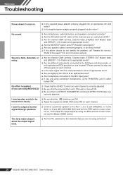
... mixer? I want spoken words to the MIC input jacks? ❑ If you are using condenser microphones, is applied. (If you are using MG166CX) ❑ Check that you are using turned ON? ❑ Are the channel GAIN controls, Channel fader, STEREO OUT Master fader and GROUP 1-2/3-4 fader set to appropriate levels? ❑ Are the MONITOR switch and 2TR IN switch set properly? ❑ Are your speaker cables connected properly, or are not using the AUX controls on ? 20 MG206C/MG166CX/MG166C Owner's Manual Then adjust the output signal by using turned...
... mixer? I want spoken words to the MIC input jacks? ❑ If you are using condenser microphones, is applied. (If you are using MG166CX) ❑ Check that you are using turned ON? ❑ Are the channel GAIN controls, Channel fader, STEREO OUT Master fader and GROUP 1-2/3-4 fader set to appropriate levels? ❑ Are the MONITOR switch and 2TR IN switch set properly? ❑ Are your speaker cables connected properly, or are not using the AUX controls on ? 20 MG206C/MG166CX/MG166C Owner's Manual Then adjust the output signal by using turned...
Owner's Manual
Page 21
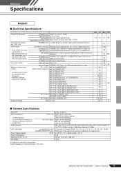
... & Noise Hum & Noise are measured with infinite dB/octave attenuation. AUX SEND Master/AUX control at nominal level and all channels' ST and 1-2, 3-4 switches off frequency of signal generator: 150 ohms MG206C/MG166CX/MG166C Owner's Manual 75 PAN/BAL: panned hard left or right Rs = 150 Ω MIC to CH INSERT OUT INPUT GAIN: maximum MIC to STEREO OUT MIC to GROUP OUT MIC to GROUP to ST MIC to REC OUT MIC to MONITOR...
... & Noise Hum & Noise are measured with infinite dB/octave attenuation. AUX SEND Master/AUX control at nominal level and all channels' ST and 1-2, 3-4 switches off frequency of signal generator: 150 ohms MG206C/MG166CX/MG166C Owner's Manual 75 PAN/BAL: panned hard left or right Rs = 150 Ω MIC to CH INSERT OUT INPUT GAIN: maximum MIC to STEREO OUT MIC to GROUP OUT MIC to GROUP to ST MIC to REC OUT MIC to MONITOR...
Owner's Manual
Page 22
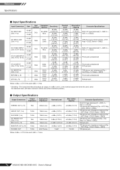
... output level when the unit is set to the maximum level. (All faders and level controls are at their maximum position.) ■ Output Specifications Output Connectors Output Impedance Appropriate Impedance STEREO OUT (L, R) 75Ω 600Ω Lines GROUP OUT (1-4) 150Ω 10kΩ Lines AUX SEND (1-4) 150Ω 10kΩ Lines CH INSERT OUT (CHs 1-12) REC OUT (L, R) 75Ω 600Ω 10kΩ Lines 10kΩ Lines MONITOR...
... output level when the unit is set to the maximum level. (All faders and level controls are at their maximum position.) ■ Output Specifications Output Connectors Output Impedance Appropriate Impedance STEREO OUT (L, R) 75Ω 600Ω Lines GROUP OUT (1-4) 150Ω 10kΩ Lines AUX SEND (1-4) 150Ω 10kΩ Lines CH INSERT OUT (CHs 1-12) REC OUT (L, R) 75Ω 600Ω 10kΩ Lines 10kΩ Lines MONITOR...
Owner's Manual
Page 23
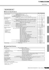
... to EFFECT/AUX* SEND Rs = 600 Ω 2TR IN to 15/16, RETURN, 2TR IN MONITOR OUT, REC OUT STEREO OUT +14 dBu @ 20 Hz-20 kHz, Input GAIN Control at minimum CH INPUT 1-8 MIC EIN (Equivalent Input Noise): Rs = 150 Ω, GAIN: maximum STEREO OUT STEREO OUT, GROUP 1-2 fader and GROUP 3-4 fader at GROUP OUT nominal level and all CH EFFECT/AUX* controls at nominal level. PEAK Indicator Internal Digital Effect (Only MG166CX) LED Level Meter Power Supply Adaptor Power Consumption Dimensions (W x H x D) Net...
... to EFFECT/AUX* SEND Rs = 600 Ω 2TR IN to 15/16, RETURN, 2TR IN MONITOR OUT, REC OUT STEREO OUT +14 dBu @ 20 Hz-20 kHz, Input GAIN Control at minimum CH INPUT 1-8 MIC EIN (Equivalent Input Noise): Rs = 150 Ω, GAIN: maximum STEREO OUT STEREO OUT, GROUP 1-2 fader and GROUP 3-4 fader at GROUP OUT nominal level and all CH EFFECT/AUX* controls at nominal level. PEAK Indicator Internal Digital Effect (Only MG166CX) LED Level Meter Power Supply Adaptor Power Consumption Dimensions (W x H x D) Net...
Owner's Manual
Page 24
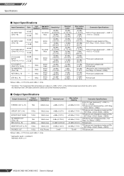
... nominal output level when the unit is set to the maximum level. (All faders and level controls are at their maximum position.) ■ Output Specifications Output Connectors Output Impedance Appropriate Impedance STEREO OUT (L, R) 75Ω 600Ω Lines GROUP OUT (1-4) 150Ω 10kΩ Lines EFFECT/AUX* SEND 150Ω 10kΩ Lines CH INSERT OUT (CHs 1-8) REC OUT (L, R) 75Ω 600Ω 10kΩ Lines 10kΩ Lines MONITOR...
... nominal output level when the unit is set to the maximum level. (All faders and level controls are at their maximum position.) ■ Output Specifications Output Connectors Output Impedance Appropriate Impedance STEREO OUT (L, R) 75Ω 600Ω Lines GROUP OUT (1-4) 150Ω 10kΩ Lines EFFECT/AUX* SEND 150Ω 10kΩ Lines CH INSERT OUT (CHs 1-8) REC OUT (L, R) 75Ω 600Ω 10kΩ Lines 10kΩ Lines MONITOR...
Owner's Manual
Page 27
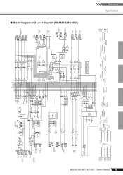
... DR LED Meter MONI/PHONES INV [-16dBu] INV SUM SUM SUM AUX SEND 1 [0dBu] [-6dBu] BA AUX SEND 2 [0dBu] [-6dBu] BA [0dBu] AUX SEND* [-6dBu] BA MONITOR MIX MODEL MG166C MG166CX AUX * AUX 3 EFFECT 1 2 GROUP OUT [+4dBu] 3 4 L STEREO OUT [+4dBu] R L REC OUT [-10dBV] R [-7.8dBu] L MONITOR OUT [+4dBu] R PHONES [3mW,40ohms] AUX SEND 1 [+4dBu] AUX SEND 2 [+4dBu] AUX SEND * [+4dBu] [-6dBu] Clip Level Clip Level Clip Level Clip Level AUX SEND *1 [+4dBu] GROUP OUT [+4dBu] AUX SEND *1 [Nominal:-6dB] GROUP Fader [Nominal:-10dB] ST Master [Nominal...
... DR LED Meter MONI/PHONES INV [-16dBu] INV SUM SUM SUM AUX SEND 1 [0dBu] [-6dBu] BA AUX SEND 2 [0dBu] [-6dBu] BA [0dBu] AUX SEND* [-6dBu] BA MONITOR MIX MODEL MG166C MG166CX AUX * AUX 3 EFFECT 1 2 GROUP OUT [+4dBu] 3 4 L STEREO OUT [+4dBu] R L REC OUT [-10dBV] R [-7.8dBu] L MONITOR OUT [+4dBu] R PHONES [3mW,40ohms] AUX SEND 1 [+4dBu] AUX SEND 2 [+4dBu] AUX SEND * [+4dBu] [-6dBu] Clip Level Clip Level Clip Level Clip Level AUX SEND *1 [+4dBu] GROUP OUT [+4dBu] AUX SEND *1 [Nominal:-6dB] GROUP Fader [Nominal:-10dB] ST Master [Nominal...


