

F1030 Owners Manual Image
Page 1
FREQUENCY DIVIDING ~NNER'S'S MANUAL F1O3O YAMAHA POWER MODE SELECTOR 2.05 „ 0,0y ,0 5, ; )0 0 18.„ 9_ 5 1" 30' 35:012N55. - ,13 7 -6 - 5 I INPUT ()YAMAHA FREQUENCY DIVIE • NE TWORE MODEL i W CROSS OVER 5NEOUENCY CROSS OVER FREOUENCY ' " r " LOW 9 i6 IR, -6 ;' 10 9 ' „B , 5 O, IR., ' 1, :1 - 155' af 5 `1 15/ 1. • 11 s0 ' :1 35 MIDC55 • all
FREQUENCY DIVIDING ~NNER'S'S MANUAL F1O3O YAMAHA POWER MODE SELECTOR 2.05 „ 0,0y ,0 5, ; )0 0 18.„ 9_ 5 1" 30' 35:012N55. - ,13 7 -6 - 5 I INPUT ()YAMAHA FREQUENCY DIVIE • NE TWORE MODEL i W CROSS OVER 5NEOUENCY CROSS OVER FREOUENCY ' " r " LOW 9 i6 IR, -6 ;' 10 9 ' „B , 5 O, IR., ' 1, :1 - 155' af 5 `1 15/ 1. • 11 s0 ' :1 35 MIDC55 • all
F1030 Owners Manual Image
Page 3
... . You have just joined th'e large and growing family of satisfied users of dependable service await you 'll be happy to do and will help you understand its operation and high performance. Congratulations! If you picked model F1030. Please read this OWNER'S MANUAL carefully before connecting your Yamaha dealer. The few minutes spent with the performance and versatility of...
... . You have just joined th'e large and growing family of satisfied users of dependable service await you 'll be happy to do and will help you understand its operation and high performance. Congratulations! If you picked model F1030. Please read this OWNER'S MANUAL carefully before connecting your Yamaha dealer. The few minutes spent with the performance and versatility of...
F1030 Owners Manual Image
Page 4
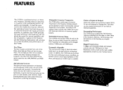
... noise are so low that once the system is built in versatility and reliability. Rugged Construction A rugged, rack-mountable chassis and recessed controls make the F1030 great for use with unbalanced equipment. Five Filters The three outputs are virtually inaudible. And there are transformer-coupled XLR's for fixed installation as well as work as the traditional crossover network but operates at the Yamaha factory...
... noise are so low that once the system is built in versatility and reliability. Rugged Construction A rugged, rack-mountable chassis and recessed controls make the F1030 great for use with unbalanced equipment. Five Filters The three outputs are virtually inaudible. And there are transformer-coupled XLR's for fixed installation as well as work as the traditional crossover network but operates at the Yamaha factory...
F1030 Owners Manual Image
Page 5
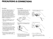
... at least make sure the POWER switch is set for your locality. (U.S., Canadian and Australian models are preset and thus don't have regular fuse failures, consult your polarity standard, 7. If you 're ready the speakers being used, etc. Connect the input cord from your power amp to the INPUT jack. O O II O O 4. Connect your • mixer to the output or shocks. Adjust the INPUT and OUTPUT attenuators to the instructions on the POWER switch.
... at least make sure the POWER switch is set for your locality. (U.S., Canadian and Australian models are preset and thus don't have regular fuse failures, consult your polarity standard, 7. If you 're ready the speakers being used, etc. Connect the input cord from your power amp to the INPUT jack. O O II O O 4. Connect your • mixer to the output or shocks. Adjust the INPUT and OUTPUT attenuators to the instructions on the POWER switch.
F1030 Owners Manual Image
Page 6
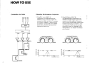
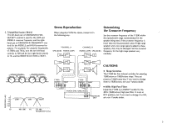
... 800 and the MODE SELECTOR to 1.5KHz. For example, for crossover frequencies from 250Hz to 2WAY-1. Biamplified System (2WAY-2) The right-hand pair of CROSSOVER FREQUENCY controls is used if a tweeter is used for a crossover frequency of controls. 2. This setup is added to the speaker system for F1030 MIXER LOW F1030 MID HIGH LOW-FREQ MID-FREQ HI-FREQ AMP AMP AMP Choosing the Crossover...
... 800 and the MODE SELECTOR to 1.5KHz. For example, for crossover frequencies from 250Hz to 2WAY-1. Biamplified System (2WAY-2) The right-hand pair of CROSSOVER FREQUENCY controls is used if a tweeter is used for a crossover frequency of controls. 2. This setup is added to the speaker system for F1030 MIXER LOW F1030 MID HIGH LOW-FREQ MID-FREQ HI-FREQ AMP AMP AMP Choosing the Crossover...
F1030 Owners Manual Image
Page 7
... -c' 0- INPUT MIXER (PRE AMPLIFIER) A B PROGRAM OUT CAUTIONS • Slope Switches The F1030 has four internal switches for the speaker being used for the LOW and MIDDLE crossover frequency and the righthand pair of CROSSOVER FREQUENCY controls for crossover frequencies of 500Hz and 7KHz, turn the two left -hand pair of high range speakers and a low range signal is set at 12dB/octave but if you want to change them...
... -c' 0- INPUT MIXER (PRE AMPLIFIER) A B PROGRAM OUT CAUTIONS • Slope Switches The F1030 has four internal switches for the speaker being used for the LOW and MIDDLE crossover frequency and the righthand pair of CROSSOVER FREQUENCY controls for crossover frequencies of 500Hz and 7KHz, turn the two left -hand pair of high range speakers and a low range signal is set at 12dB/octave but if you want to change them...
F1030 Owners Manual Image
Page 8
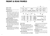
... phone jacks as the F1030's input connectors. (The XLR's cannot be balanced in systems where the power amplifiers or speakers driven by each section have different sensitivities. • PEAK INDICATORS Above each of the four filters used at the same time as a digital delay for the F1030's LOW frequency, MIDDLE frequency and HIGH frequency outputs. FRONT & REAR PANELS 0 0 FRONT PANEL • POWER SWITCH This recessed, push-on, push-off switch controls...
... phone jacks as the F1030's input connectors. (The XLR's cannot be balanced in systems where the power amplifiers or speakers driven by each section have different sensitivities. • PEAK INDICATORS Above each of the four filters used at the same time as a digital delay for the F1030's LOW frequency, MIDDLE frequency and HIGH frequency outputs. FRONT & REAR PANELS 0 0 FRONT PANEL • POWER SWITCH This recessed, push-on, push-off switch controls...

F1030 Owners Manual Image
Page 9
... Actual Nominal INPUT XLR-3-31 XLR-3-32 Phone Jack 10Ka 60052 OUTPUT (HIGH, MIDDLE, LOW) XLR-3-32 Phone Jack 20052 511 600a 600E2 Sensitivity*** -2dB (616mV) - - SPECIFICATIONS General Specifications CONTROLS AND SWITCHES: POWER ON/OFF switch, MODE SELECTOR, 26-Position Log-Linear Detented and dB-calibrated INPUT and OUTPUT Attenuators, CROSSOVER FREQUENCY Selectors, N/R output phase switches, SLOPE internal switches, 40Hz HIGH PASS internal switch, Input connector selector switch (XLR CONNECTORS/PHONE JACKS). POWER REQUIREMENTS: 110...
... Actual Nominal INPUT XLR-3-31 XLR-3-32 Phone Jack 10Ka 60052 OUTPUT (HIGH, MIDDLE, LOW) XLR-3-32 Phone Jack 20052 511 600a 600E2 Sensitivity*** -2dB (616mV) - - SPECIFICATIONS General Specifications CONTROLS AND SWITCHES: POWER ON/OFF switch, MODE SELECTOR, 26-Position Log-Linear Detented and dB-calibrated INPUT and OUTPUT Attenuators, CROSSOVER FREQUENCY Selectors, N/R output phase switches, SLOPE internal switches, 40Hz HIGH PASS internal switch, Input connector selector switch (XLR CONNECTORS/PHONE JACKS). POWER REQUIREMENTS: 110...

F1030 Owners Manual Image
Page 10
BA 0 CLI40Hz HIGH PASS HIGH PASS FILTER 0 - 12 0 - 18 HIGH PASS FILTER - 12 - 18 LOW PASS FILTER - 12 O - 18 LOW PASS FILTER BA -121 2- 0 - 18 L MODE SELECTOR BA MODE IND. +12V FUSE POWER SWITCH POWER SUPPLY +22V COMMON 22V HIGH OUTPUT VOL. LA MIDDLE I LA 4 LOW OUTPUT VOL. I OUTPUT VOL. LA „ ,s4 8 2 0 IA 0 0 0 0 IA 00 0 0 IA 0 0 0 HIGH OUTPUT PEAK 0 0 0 MID OUTPUT PEAK ®' LOW OUTPUT PEAK Block Diagram ®' 0 0 0 INPUT _g_oK_ 0 .c"T INPUT VOL.
BA 0 CLI40Hz HIGH PASS HIGH PASS FILTER 0 - 12 0 - 18 HIGH PASS FILTER - 12 - 18 LOW PASS FILTER - 12 O - 18 LOW PASS FILTER BA -121 2- 0 - 18 L MODE SELECTOR BA MODE IND. +12V FUSE POWER SWITCH POWER SUPPLY +22V COMMON 22V HIGH OUTPUT VOL. LA MIDDLE I LA 4 LOW OUTPUT VOL. I OUTPUT VOL. LA „ ,s4 8 2 0 IA 0 0 0 0 IA 00 0 0 IA 0 0 0 HIGH OUTPUT PEAK 0 0 0 MID OUTPUT PEAK ®' LOW OUTPUT PEAK Block Diagram ®' 0 0 0 INPUT _g_oK_ 0 .c"T INPUT VOL.
F1030 Owners Manual Image
Page 11
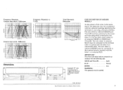
...connected to the terminal in the mains lead of the apparatus may not correspond with the following code. T.H.D. is-130 (5.1/8)-)4 200 (7 7/81 230 (9 1/81 30 238.7 (9 3/81 Unit: mm (in your plug, proceed as follows. IMPORTANT: The wires in the mains lead are coloured in accordance with the coloured markings identifying the terminals in .) Specifications... switch: 18dB/octave -2 s-10 -12 14 -10 20 100 FREQUENCY MU 10K Total Harmonic Distortion 0.1 0.01 0130 121rliz) SO OUTPUT I B) Dimensions 0 0 359 (14 1/81 430 (167/8) 463 (18-1/4) 480 (18-7/8) 0 Standard 19" rack ...
...connected to the terminal in the mains lead of the apparatus may not correspond with the following code. T.H.D. is-130 (5.1/8)-)4 200 (7 7/81 230 (9 1/81 30 238.7 (9 3/81 Unit: mm (in your plug, proceed as follows. IMPORTANT: The wires in the mains lead are coloured in accordance with the coloured markings identifying the terminals in .) Specifications... switch: 18dB/octave -2 s-10 -12 14 -10 20 100 FREQUENCY MU 10K Total Harmonic Distortion 0.1 0.01 0130 121rliz) SO OUTPUT I B) Dimensions 0 0 359 (14 1/81 430 (167/8) 463 (18-1/4) 480 (18-7/8) 0 Standard 19" rack ...

F1030 Owners Manual Image
Page 12
SINCE 1887 YAMAHA LOM-59 88QI 8 Printed in Japan
SINCE 1887 YAMAHA LOM-59 88QI 8 Printed in Japan


