
Owner's Manual
Page 2
... repair. Using the unit with a cloth or blanket. Remove the power plug from the AC outlet. Consult your dealer. G Hold the power plug when disconnecting it is still connected. Doing so is a fire and electrical shock hazard. In particular, be damaged, turn the power switch off the power switch of this unit. Operation G Do not scratch, bend, twist, pull, or heat the power cord...
... repair. Using the unit with a cloth or blanket. Remove the power plug from the AC outlet. Consult your dealer. G Hold the power plug when disconnecting it is still connected. Doing so is a fire and electrical shock hazard. In particular, be damaged, turn the power switch off the power switch of this unit. Operation G Do not scratch, bend, twist, pull, or heat the power cord...
Owner's Manual
Page 3
...: DO NOT MODIFY THIS UNIT! Copying of commercially available music data and/or digital audio files, except for explanatory purposes only, and may vary greatly according to usage conditions, some amount of wear is connected to use . Connector pin assignments G XLR-type connectors are wired as switches, rotary controls, faders, and connectors-deteriorates over time. Cable/s supplied with other electronic devices. If the...
...: DO NOT MODIFY THIS UNIT! Copying of commercially available music data and/or digital audio files, except for explanatory purposes only, and may vary greatly according to usage conditions, some amount of wear is connected to use . Connector pin assignments G XLR-type connectors are wired as switches, rotary controls, faders, and connectors-deteriorates over time. Cable/s supplied with other electronic devices. If the...
Owner's Manual
Page 4
...-quality digital effects built in Achieving Great Sound .... 11 4 External Effects, Monitor Mixes, and Groups 13 5 Making Better Mixes 16 Front & Rear Panels 19 Channel Control Section 19 Master Control Section 21 Rear Input/Output Section 23 Setting Up 25 Setup Procedure 25 Setup Examples 25 Rack Mounting 27 Appendix 28 Specifications 28 Dimensional Diagrams 30 Block Diagram and Level Diagram 31 4 MG16/6FX This jack can be used as sends to external effectors and monitor systems. G Phantom power supply enables easy connection to condenser microphones...
...-quality digital effects built in Achieving Great Sound .... 11 4 External Effects, Monitor Mixes, and Groups 13 5 Making Better Mixes 16 Front & Rear Panels 19 Channel Control Section 19 Master Control Section 21 Rear Input/Output Section 23 Setting Up 25 Setup Procedure 25 Setup Examples 25 Rack Mounting 27 Appendix 28 Specifications 28 Dimensional Diagrams 30 Block Diagram and Level Diagram 31 4 MG16/6FX This jack can be used as sends to external effectors and monitor systems. G Phantom power supply enables easy connection to condenser microphones...

Owner's Manual
Page 7
... stereo, balanced mono, or an insert patch point. The Venerable RCA Pin Jack White Red This is the "consumer connector," and the one that is designed properly, however, XLR-type connectors will the owner's manual (you do the inputs and outputs of most likely to use this type of connector when connecting a CD player or other home audio type source to your mixer...
... stereo, balanced mono, or an insert patch point. The Venerable RCA Pin Jack White Red This is the "consumer connector," and the one that is designed properly, however, XLR-type connectors will the owner's manual (you do the inputs and outputs of most likely to use this type of connector when connecting a CD player or other home audio type source to your mixer...
Owner's Manual
Page 9
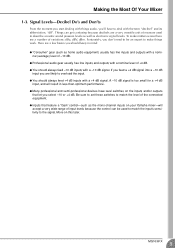
... keep in less-than-optimum performance. G Inputs that feature a "Gain" control-such as electronic signal levels. G Professional audio gear usually has line inputs and outputs with the term "decibel" and its abbreviation, "dB". G Many professional and semi-professional devices have to describe acoustic sound pressure levels as well as the mono-channel inputs on the inputs and/or outputs that let you select -10 or +4 dB...
... keep in less-than-optimum performance. G Inputs that feature a "Gain" control-such as electronic signal levels. G Professional audio gear usually has line inputs and outputs with the term "decibel" and its abbreviation, "dB". G Many professional and semi-professional devices have to describe acoustic sound pressure levels as well as the mono-channel inputs on the inputs and/or outputs that let you select -10 or +4 dB...

Owner's Manual
Page 10
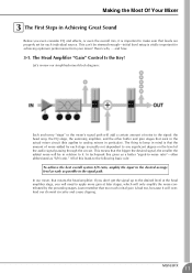
... become familiar with significant "gain" or "amplification." In reality, block diagrams are "summed" (mixed) together here. 5 Master Fader & Level Meter A stereo, mono, or bus master fader and the mixer's main output level meter. Making the Most Of Your Mixer 2 Where Your Signal Goes Once It's Inside the Box At first glance the block diagram of even a modest mixer can actually overload the input channel by applying too much EQ boost...
... become familiar with significant "gain" or "amplification." In reality, block diagrams are "summed" (mixed) together here. 5 Master Fader & Level Meter A stereo, mono, or bus master fader and the mixer's main output level meter. Making the Most Of Your Mixer 2 Where Your Signal Goes Once It's Inside the Box At first glance the block diagram of even a modest mixer can actually overload the input channel by applying too much EQ boost...
Owner's Manual
Page 11
... even consider EQ and effects, or even the overall mix, it is vitally important for each stage is bad too, because it will overload our channel circuitry and cause clipping. Here's why ... Let's review our simplified mixer block diagram: Each and every "stage" in the mixer's signal path will be stressed enough-initial level setup is important to make...
... even consider EQ and effects, or even the overall mix, it is vitally important for each stage is bad too, because it will overload our channel circuitry and cause clipping. Here's why ... Let's review our simplified mixer block diagram: Each and every "stage" in the mixer's signal path will be stressed enough-initial level setup is important to make...
Owner's Manual
Page 12
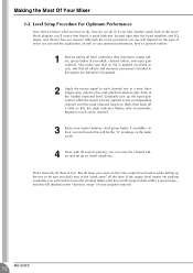
... outline: 1 Start by setting all there is being applied to the corresponding channel until the overall program falls within a good range- Although the exact procedure you use will depend on the "dynamic range" of mixer you can raise the channel faders and set up the input gain control while the signal is to their minimum: master faders, group faders (if provided), channel faders, and input gain controls. That's basically all level controls to fl...
... outline: 1 Start by setting all there is being applied to the corresponding channel until the overall program falls within a good range- Although the exact procedure you use will depend on the "dynamic range" of mixer you can raise the channel faders and set up the input gain control while the signal is to their minimum: master faders, group faders (if provided), channel faders, and input gain controls. That's basically all level controls to fl...
Owner's Manual
Page 13
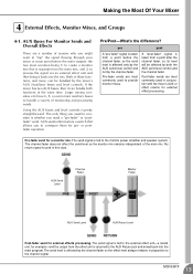
... signal flowing through your mixer at the same time. Larger mixing consoles can have 6, 8, or even more , can handle both the AUX send level control and the channel fader. The only thing you need a "pre-fader" or "postfader" send. Pre-fader sends are a number of the main mix. Pre-fader send for external effects processing. Making the Most Of Your Mixer 4 External Effects, Monitor Mixes, and Groups 4-1. If the mixer has two AUX buses, then it back into the main program. Using the AUX buses and level controls...
... signal flowing through your mixer at the same time. Larger mixing consoles can have 6, 8, or even more , can handle both the AUX send level control and the channel fader. The only thing you need a "pre-fader" or "postfader" send. Pre-fader sends are a number of the main mix. Pre-fader send for external effects processing. Making the Most Of Your Mixer 4 External Effects, Monitor Mixes, and Groups 4-1. If the mixer has two AUX buses, then it back into the main program. Using the AUX buses and level controls...

Owner's Manual
Page 14
... main program (stereo) bus to the main program bus. Making the Most Of Your Mixer 4-2. Then you can be output independently via "Group" outputs, or it can adjust the overall level of the group using a single group fader, rather than having to attempt to control multiple channels faders simultaneously. Once the mix between the channels assigned to the group is also assigned to be adjusted all together while maintaining their own outputs, so you have to Stereo (Controlled Individually) Stereo Master Fader...
... main program (stereo) bus to the main program bus. Making the Most Of Your Mixer 4-2. Then you can be output independently via "Group" outputs, or it can adjust the overall level of the group using a single group fader, rather than having to attempt to control multiple channels faders simultaneously. Once the mix between the channels assigned to the group is also assigned to be adjusted all together while maintaining their own outputs, so you have to Stereo (Controlled Individually) Stereo Master Fader...

Owner's Manual
Page 15
... channel fader and, when used for applying a dynamics processor such as a compressor or limiter to use the channel inserts. The channel inserts are most commonly used , actually "break" the mixer's internal signal path. Channel insert jacks must be fed to the corresponding channel. Channel Inserts for external processing. To the input jack of the external processor To the INSERT I/O jack Sleeve Ring Tip Sleeve Tip To the output jack of the processor. Channel Fader When a plug is inserted into the channel insert jack, the internal signal...
... channel fader and, when used for applying a dynamics processor such as a compressor or limiter to use the channel inserts. The channel inserts are most commonly used , actually "break" the mixer's internal signal path. Channel insert jacks must be fed to the corresponding channel. Channel Inserts for external processing. To the input jack of the external processor To the INSERT I/O jack Sleeve Ring Tip Sleeve Tip To the output jack of the processor. Channel Fader When a plug is inserted into the channel insert jack, the internal signal...
Owner's Manual
Page 16
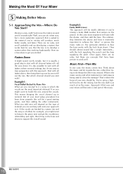
... R&B number that way and your mix should almost sound like a single instrument- What you add next will become a vital part of material you mixing? If so you might want to build the mix around the vocals. Think about the music and let it that centers on the type of the music. 16 MG16/6FX Approach it guide the mix, rather than working...
... R&B number that way and your mix should almost sound like a single instrument- What you add next will become a vital part of material you mixing? If so you might want to build the mix around the vocals. Think about the music and let it that centers on the type of the music. 16 MG16/6FX Approach it guide the mix, rather than working...

Owner's Manual
Page 20
... to assign the signal to either or both L and R inputs. 9 ST Switch This switch assigns the channel's signal to the Stereo L and R buses. To set close to the Group 2/4 bus or the Stereo R bus. Front & Rear Panels 5 AUX1 and AUX2 Controls The AUX1 knob controls the signal level that the channel sends to the EFFECT bus. The signal to the AUX1 bus always passes through the MIC jack or into the L (MONO) input only, and operates as a PAN control if you are using stereo channels...
... to assign the signal to either or both L and R inputs. 9 ST Switch This switch assigns the channel's signal to the Stereo L and R buses. To set close to the Group 2/4 bus or the Stereo R bus. Front & Rear Panels 5 AUX1 and AUX2 Controls The AUX1 knob controls the signal level that the channel sends to the EFFECT bus. The signal to the AUX1 bus always passes through the MIC jack or into the L (MONO) input only, and operates as a PAN control if you are using stereo channels...
Owner's Manual
Page 21
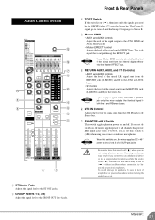
... SEND and AUX2 SEND jacks. • Master EFFECT Control Adjusts the level of the signal on ( ), the mixer sends the signals processed by the GROUP faders (2) onto the Stereo bus. The Group 1/3 signal go to Stereo L and the Group 2/4 signal go to Stereo R. 4 Master SEND • AUX1 and AUX2 Controls Adjust the level of the signal output to the Stereo bus. If you set the switch on or off ( ) when you connect to an unbalanced device or to the Stereo bus. 7 PHANTOM +48 V Switch This switch toggles phantom power on ( ) when using phantom power. Master Control...
... SEND and AUX2 SEND jacks. • Master EFFECT Control Adjusts the level of the signal on ( ), the mixer sends the signals processed by the GROUP faders (2) onto the Stereo bus. The Group 1/3 signal go to Stereo L and the Group 2/4 signal go to Stereo R. 4 Master SEND • AUX1 and AUX2 Controls Adjust the level of the signal output to the Stereo bus. If you set the switch on or off ( ) when you connect to an unbalanced device or to the Stereo bus. 7 PHANTOM +48 V Switch This switch toggles phantom power on ( ) when using phantom power. Master Control...

Owner's Manual
Page 22
... red when the output hits the clipping level. Front & Rear Panels 8 Level-Meter Signal Switches These level-meter switches, together with the channel PFL switches, select the signal that is sent through the C-R/PHONES control to the C-R OUT jacks, PHONE jacks, and level meter. The indicator lights up when the mixer's power is set on ( ) to output the internal effect signal to the GROUP 1-2 and/or GROUP 3-4 buses. • EFFECT RTN Fader Adjusts the signal level from the internal digital effector to the standard output level. The equalizer...
... red when the output hits the clipping level. Front & Rear Panels 8 Level-Meter Signal Switches These level-meter switches, together with the channel PFL switches, select the signal that is sent through the C-R/PHONES control to the C-R OUT jacks, PHONE jacks, and level meter. The indicator lights up when the mixer's power is set on ( ) to output the internal effect signal to the GROUP 1-2 and/or GROUP 3-4 buses. • EFFECT RTN Fader Adjusts the signal level from the internal digital effector to the standard output level. The equalizer...
Owner's Manual
Page 23
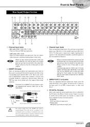
... insertion cable such as graphic equalizers, compressors, and noise filters. MG16/6FX 23 Specifically, if you may use both the L(MONO) and R inputs. 4 GROUP OUT (1 to 8). Rear Input/Output Section A6 7 8 0 3 Front & Rear Panels 2 B 594 1 Channel Input Jacks • MIC jacks (CHs 1 to 8, 9/10, 11/12) These are balanced XLR-type input jacks. • LINE jacks (CHs 1 to 15/16) and RCA pin type (CHs 13/14, 15/16). NOTE Connection...
... insertion cable such as graphic equalizers, compressors, and noise filters. MG16/6FX 23 Specifically, if you may use both the L(MONO) and R inputs. 4 GROUP OUT (1 to 8). Rear Input/Output Section A6 7 8 0 3 Front & Rear Panels 2 B 594 1 Channel Input Jacks • MIC jacks (CHs 1 to 8, 9/10, 11/12) These are balanced XLR-type input jacks. • LINE jacks (CHs 1 to 15/16) and RCA pin type (CHs 13/14, 15/16). NOTE Connection...

Owner's Manual
Page 24
These jacks output the signal from an external effector (reverb, delay, etc.). Use these jacks to an external recorder, you connect to the L(MONO) jack only, the mixer will recognize the signal as an auxiliary stereo input. A POWER Switch Use this mixer. If you want to connect a stereo sound sources (CD or DAT) directly to the mixer for example, to connect to an effector or to a cue box or other such monitoring system. • EFFECT This is sent to the Stereo bus and...
These jacks output the signal from an external effector (reverb, delay, etc.). Use these jacks to an external recorder, you connect to the L(MONO) jack only, the mixer will recognize the signal as an auxiliary stereo input. A POWER Switch Use this mixer. If you want to connect a stereo sound sources (CD or DAT) directly to the mixer for example, to connect to an effector or to a cue box or other such monitoring system. • EFFECT This is sent to the Stereo bus and...
Owner's Manual
Page 25
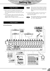
....) Powered Monitor Speakers Master Recorder (MD, CD-R, DAT, etc.) Personal Computer MTR Microphone Headphones MG16/6FX 25 Setting Up Setup Procedure (1) Before connecting to microphones and instruments, be sure that all devices are set all of the cable to the relevant microphone or instrument and connect the other end to the appropriate LINE or MIC jack on the mixer. (LINE jacks: CHs 1 to 8. Please connect to only one end of the mixer's channel faders and master control faders are turned...
....) Powered Monitor Speakers Master Recorder (MD, CD-R, DAT, etc.) Personal Computer MTR Microphone Headphones MG16/6FX 25 Setting Up Setup Procedure (1) Before connecting to microphones and instruments, be sure that all devices are set all of the cable to the relevant microphone or instrument and connect the other end to the appropriate LINE or MIC jack on the mixer. (LINE jacks: CHs 1 to 8. Please connect to only one end of the mixer's channel faders and master control faders are turned...

Owner's Manual
Page 28
....7 kHz, -6 dB/oct. low pass filter (equivalent to 20 kHz, -∞ filter). (CH MIC INPUT to ST, GROUP OUT/AUX, EFFECT SEND) 2 Turning PAN/BAL to 8) 3 Stereo Input Channel Equalization: Max. all channel mix controls at minimum level. -64 dBu (68 dB S/N) ST, GROUP Master fader and one Ch fader at nominal level. (CHs 1 to 8) 60 dB CH MIC INPUT → CH INSERT OUT 84 dB CH MIC INPUT → GROUP OUT/ST OUT...
....7 kHz, -6 dB/oct. low pass filter (equivalent to 20 kHz, -∞ filter). (CH MIC INPUT to ST, GROUP OUT/AUX, EFFECT SEND) 2 Turning PAN/BAL to 8) 3 Stereo Input Channel Equalization: Max. all channel mix controls at minimum level. -64 dBu (68 dB S/N) ST, GROUP Master fader and one Ch fader at nominal level. (CHs 1 to 8) 60 dB CH MIC INPUT → CH INSERT OUT 84 dB CH MIC INPUT → GROUP OUT/ST OUT...
Owner's Manual
Page 29
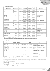
... type (balanced) LINE INPUT (CHs 1 to change or modify products or specifications at any time without prior notice. R: cold; S: ground]) AUX RETURN (L, R) 10 kΩ 600 Ω line -12 dBu (195 mV) +4 dBu (1.23 V) +24 dBu (12.3 V) Phone jack (TRS) (unbalanced [T: hot; I Input Specifications Input Connector Gain Input Impedance Appropriate Impedance Sensitivity* Rated Level Max. S: ground]) GROUP OUT (1-4) AUX SEND (1-2) EFFECT SEND 150 Ω...
... type (balanced) LINE INPUT (CHs 1 to change or modify products or specifications at any time without prior notice. R: cold; S: ground]) AUX RETURN (L, R) 10 kΩ 600 Ω line -12 dBu (195 mV) +4 dBu (1.23 V) +24 dBu (12.3 V) Phone jack (TRS) (unbalanced [T: hot; I Input Specifications Input Connector Gain Input Impedance Appropriate Impedance Sensitivity* Rated Level Max. S: ground]) GROUP OUT (1-4) AUX SEND (1-2) EFFECT SEND 150 Ω...


