
Owner's Manual
Page 2
... Adjusting the Monitor Levels from the DAW 41 Using Scene Memories 42 Changing the Channel Names 43 Creating a Custom Layer by Combining Channels (User Assignable Layer) ....... 44 Using the Oscillator 45 Using the User Defined Keys 46 Using Operation Lock 47 Initializing 48 Troubleshooting 49 Error messages 51 Contents of the Reference Manual 54 Specifications 55 General Spec 55 Libraries 60 Analog Input Spec 61 Analog Output Specs 61 Digital Input Spec 62 Digital Output Spec 62 I/O SLOT Spec 63 MIDI/USB/WORD CLOCK I/O Spec .... 64 Dimensions 64 Options 65 Rack...
... Adjusting the Monitor Levels from the DAW 41 Using Scene Memories 42 Changing the Channel Names 43 Creating a Custom Layer by Combining Channels (User Assignable Layer) ....... 44 Using the Oscillator 45 Using the User Defined Keys 46 Using Operation Lock 47 Initializing 48 Troubleshooting 49 Error messages 51 Contents of the Reference Manual 54 Specifications 55 General Spec 55 Libraries 60 Analog Input Spec 61 Analog Output Specs 61 Digital Input Spec 62 Digital Output Spec 62 I/O SLOT Spec 63 MIDI/USB/WORD CLOCK I/O Spec .... 64 Dimensions 64 Options 65 Rack...
Owner's Manual
Page 7
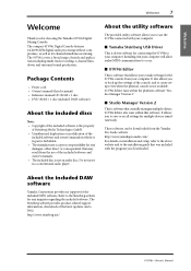
... owner's manuals in whole or in part is driver software for the 01V96i console from the Yamaha Pro Audio website. Installing it in your computer will allow audio/MIDI communication to occur. ■ 01V96i Editor This is not an audio disc. http://www.yamahaproaudio.com/ For details on installation and setup, refer to the above website and to use of needs and applications including multi-track recording, 2-channel mixdown, and surround sound...
... owner's manuals in whole or in part is driver software for the 01V96i console from the Yamaha Pro Audio website. Installing it in your computer will allow audio/MIDI communication to occur. ■ 01V96i Editor This is not an audio disc. http://www.yamahaproaudio.com/ For details on installation and setup, refer to the above website and to use of needs and applications including multi-track recording, 2-channel mixdown, and surround sound...
Owner's Manual
Page 10
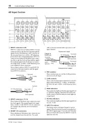
... cable to insert an external effects processor to these connectors. Adjust the Pad switch and GAIN control so that accept line-level and microphone signals. Phantom power is not supplied to AD input channels. Male XLR plug 1 (ground) 3 (cold) 2 (hot) 1/4" TRS phone plug Tip (hot) Ring (cold) Sleeve (ground) 2 INPUT connectors 13-16 These balanced TRS phone-type connectors accept line-level signals. When the button is 3 dB below clipping. 10 Control Surface & Rear Panel AD Input Section 1 3 4 5 6 7 1 2 3 4 5 A A A A A B B B B B INPUT...
... cable to insert an external effects processor to these connectors. Adjust the Pad switch and GAIN control so that accept line-level and microphone signals. Phantom power is not supplied to AD input channels. Male XLR plug 1 (ground) 3 (cold) 2 (hot) 1/4" TRS phone plug Tip (hot) Ring (cold) Sleeve (ground) 2 INPUT connectors 13-16 These balanced TRS phone-type connectors accept line-level signals. When the button is 3 dB below clipping. 10 Control Surface & Rear Panel AD Input Section 1 3 4 5 6 7 1 2 3 4 5 A A A A A B B B B B INPUT...
Owner's Manual
Page 16
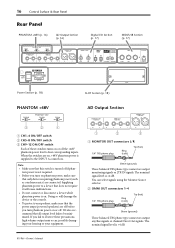
... your speakers, make sure that all output level faders be minimized. When the switches are off the +48V phantom power feed to four corresponding inputs. The nominal signal level is +4 dB. 01V96i-Owner's Manual You can select signals using the Monitor Source selector. 2 OMNI OUT connectors 1-4 1/4" TRS phone plug Ring (cold) Tip (hot) Sleeve (ground) These balanced TRS phone-type connectors output any Bus signals or channel Direct Out signals. The nominal signal level is...
... your speakers, make sure that all output level faders be minimized. When the switches are off the +48V phantom power feed to four corresponding inputs. The nominal signal level is +4 dB. 01V96i-Owner's Manual You can select signals using the Monitor Source selector. 2 OMNI OUT connectors 1-4 1/4" TRS phone plug Ring (cold) Tip (hot) Sleeve (ground) These balanced TRS phone-type connectors output any Bus signals or channel Direct Out signals. The nominal signal level is...
Owner's Manual
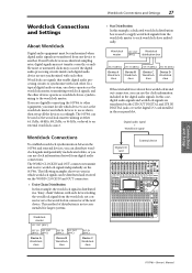
Page 27
... SIGNAL 20dB +4 GAIN -26 +4 GAIN -26 0 LEVEL10 -16 -60 GAIN +4 GAIN -26 +4 GAIN -26 MONITOR OUT PEAK SIGNAL 13 PEAK SIGNAL 14 15 PEAK SIGNAL 16 0 LEVEL10 PHONES DISPLAY ACCESS SCENE MEMORY SCENE DIO/SETUP MIDI UTILITY / INSERT/ PAN/ PAIR/ DELAY ROUTING GROUP PATCH DYNAMICS EQ EFFECT FADER MODE VIEW AUX 1 AUX 2 AUX 3 AUX 4 AUX 5 AUX 6 AUX 7 AUX 8 HOME (METER) LAYER 1-16 17-32 MASTER REMOTE OVER 0 -3 -6 -9 -12 -15 -18 -24 -30 -36 -48 STEREO STORE DEC Q HIGH HIGH-MID FREQUENCY LOW-MID GAIN LOW ENTER RECALL...
... SIGNAL 20dB +4 GAIN -26 +4 GAIN -26 0 LEVEL10 -16 -60 GAIN +4 GAIN -26 +4 GAIN -26 MONITOR OUT PEAK SIGNAL 13 PEAK SIGNAL 14 15 PEAK SIGNAL 16 0 LEVEL10 PHONES DISPLAY ACCESS SCENE MEMORY SCENE DIO/SETUP MIDI UTILITY / INSERT/ PAN/ PAIR/ DELAY ROUTING GROUP PATCH DYNAMICS EQ EFFECT FADER MODE VIEW AUX 1 AUX 2 AUX 3 AUX 4 AUX 5 AUX 6 AUX 7 AUX 8 HOME (METER) LAYER 1-16 17-32 MASTER REMOTE OVER 0 -3 -6 -9 -12 -15 -18 -24 -30 -36 -48 STEREO STORE DEC Q HIGH HIGH-MID FREQUENCY LOW-MID GAIN LOW ENTER RECALL...
Owner's Manual
Page 39
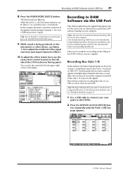
.... 1. Recording Bus Outs 1-8 In this example, the faders control the send level of multiple Input Channels and stereo-record them. Use this , refer to Aux 1 (Effects processor 1 input). Tip: The Input Channels that you want to record must have installed the Yamaha Steinberg USB Driver on how to do this method if you want to mix the signals of the signals routed from each Input Channel to normal mode, press the FADER MODE [HOME] button. 9. For details on your DAW. Tutorial 01V96i-Owner's Manual
.... 1. Recording Bus Outs 1-8 In this example, the faders control the send level of multiple Input Channels and stereo-record them. Use this , refer to Aux 1 (Effects processor 1 input). Tip: The Input Channels that you want to record must have installed the Yamaha Steinberg USB Driver on how to do this method if you want to mix the signals of the signals routed from each Input Channel to normal mode, press the FADER MODE [HOME] button. 9. For details on your DAW. Tutorial 01V96i-Owner's Manual

Owner's Manual
Page 49
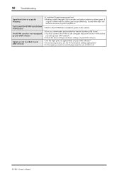
... insert turned on , panel LEDs or LCD won't light Sound is not input Sound is not output Sound is not output from the MONITOR OUT or PHONES jack Noise is present in an externally connected recorder or device High-frequency range is lacking An input signal is being input, but there's no monitor output Headroom is restricted, particularly when EQ boost is applied Signal is delayed Can't save a read-only scene/library memory, or a protected scene...
... insert turned on , panel LEDs or LCD won't light Sound is not input Sound is not output Sound is not output from the MONITOR OUT or PHONES jack Noise is present in an externally connected recorder or device High-frequency range is lacking An input signal is being input, but there's no monitor output Headroom is restricted, particularly when EQ boost is applied Signal is delayed Can't save a read-only scene/library memory, or a protected scene...
Owner's Manual
Page 50
... USB1-16? 01V96i-Owner's Manual 50 Troubleshooting Signal level is low at a specific frequency Can't control the 01V96i console from 01V96i Editor The 01V96i console is mixed with the same signal routed differently, a comb filter effect will decrease the level at specific frequencies. ❍ Refer to the 01V96i Editor installation guide on the website. ❍ Have you downloaded and installed the Yamaha Steinberg USB Driver? ❍ You must connect the 01V96i to the computer and power-on the 01V96i before you want...
... USB1-16? 01V96i-Owner's Manual 50 Troubleshooting Signal level is low at a specific frequency Can't control the 01V96i console from 01V96i Editor The 01V96i console is mixed with the same signal routed differently, a comb filter effect will decrease the level at specific frequencies. ❍ Refer to the 01V96i Editor installation guide on the website. ❍ Have you downloaded and installed the Yamaha Steinberg USB Driver? ❍ You must connect the 01V96i to the computer and power-on the 01V96i before you want...
Owner's Manual
Page 51
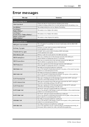
.... Error messages 51 Error messages Message Memory backup issues Check Sum Error! Try again. Replace the battery. Check the serial bridge settings of data being received is low. The SLOT1 serial port transmission buffer has overflowed. Low Battery ! Full SLOT1 Framing Error SLOT1 Overrun Error SLOT1 Parity Error SLOT1 RxBuf. The USB port reception buffer has overflowed. Cause: The amount of time. Low Battery! Low Battery ! Replace Battery ! Communication issues MIDI port is connected. Memory...
.... Error messages 51 Error messages Message Memory backup issues Check Sum Error! Try again. Replace the battery. Check the serial bridge settings of data being received is low. The SLOT1 serial port transmission buffer has overflowed. Low Battery ! Full SLOT1 Framing Error SLOT1 Overrun Error SLOT1 Parity Error SLOT1 RxBuf. The USB port reception buffer has overflowed. Cause: The amount of time. Low Battery! Low Battery ! Replace Battery ! Communication issues MIDI port is connected. Memory...

Owner's Manual
Page 54
... to Aux Sends 42 Input & Output Patching 43 Input Patching 43 Output Patching 44 Patching Direct Outs 46 Insert Patching 47 Monitoring 49 Monitor 49 Monitor and Solo Setup 49 Using the Monitor 50 Using the Solo Function 51 Surround Pan 52 About Surround Pan 52 Setting Up and Selecting Surround Pan Modes 53 Surround Panning 56 Grouping Channels & Linking Parameters .......... 59 Grouping & Linking 59 Using Fader Groups and Mute Groups 59 Using Fader Group Master 61 Using Mute Group Master 62 Linking EQ and Compressor Parameters 62 Internal Effects...
... to Aux Sends 42 Input & Output Patching 43 Input Patching 43 Output Patching 44 Patching Direct Outs 46 Insert Patching 47 Monitoring 49 Monitor 49 Monitor and Solo Setup 49 Using the Monitor 50 Using the Solo Function 51 Surround Pan 52 About Surround Pan 52 Setting Up and Selecting Surround Pan Modes 53 Surround Panning 56 Grouping Channels & Linking Parameters .......... 59 Grouping & Linking 59 Using Fader Groups and Mute Groups 59 Using Fader Group Master 61 Using Mute Group Master 62 Linking EQ and Compressor Parameters 62 Internal Effects...

Owner's Manual
Page 66
... LOW button 14 LOW-MID button 14 M MASTER button 13 Master page 23 Metering 23 MIDI button 12 MIDI IN/THRU/OUT ports 17 MIDI indicator 19 MIDI/USB Section 17 mini-YGDAI (Yamaha General Digital Audio Interface) I/O cards ....18 Mixing system 25 MONITOR LEVEL control 11 Monitor Levels 41 Monitor Out & Headphones Section ..11 MONITOR OUT connectors L/R ......16 Monitor Source selector 11 N Name Input Auto Copy check box ....43 O OMNI OUT connectors 1-4 16 ON buttons 11, 12 Operating Basics 19 OPERATION LOCK 47 Operation Lock 47 OPERATION LOCK...
... LOW button 14 LOW-MID button 14 M MASTER button 13 Master page 23 Metering 23 MIDI button 12 MIDI IN/THRU/OUT ports 17 MIDI indicator 19 MIDI/USB Section 17 mini-YGDAI (Yamaha General Digital Audio Interface) I/O cards ....18 Mixing system 25 MONITOR LEVEL control 11 Monitor Levels 41 Monitor Out & Headphones Section ..11 MONITOR OUT connectors L/R ......16 Monitor Source selector 11 N Name Input Auto Copy check box ....43 O OMNI OUT connectors 1-4 16 ON buttons 11, 12 Operating Basics 19 OPERATION LOCK 47 Operation Lock 47 OPERATION LOCK...

Reference Manual
Page 2
... to Aux Sends 42 Input & Output Patching 43 Input Patching 43 Output Patching 44 Patching Direct Outs 46 Insert Patching 47 Monitoring 49 Monitor 49 Monitor and Solo Setup 49 Using the Monitor 50 Using the Solo Function 51 Surround Pan 52 About Surround Pan 52 Setting Up and Selecting Surround Pan Modes 53 Surround Panning 56 Grouping Channels & Linking Parameters .......... 59 Grouping & Linking 59 Using Fader Groups and Mute Groups 59 Using Fader Group Master 61 Using Mute Group Master 62 Linking EQ and Compressor Parameters 62 Internal Effects...
... to Aux Sends 42 Input & Output Patching 43 Input Patching 43 Output Patching 44 Patching Direct Outs 46 Insert Patching 47 Monitoring 49 Monitor 49 Monitor and Solo Setup 49 Using the Monitor 50 Using the Solo Function 51 Surround Pan 52 About Surround Pan 52 Setting Up and Selecting Surround Pan Modes 53 Surround Panning 56 Grouping Channels & Linking Parameters .......... 59 Grouping & Linking 59 Using Fader Groups and Mute Groups 59 Using Fader Group Master 61 Using Mute Group Master 62 Linking EQ and Compressor Parameters 62 Internal Effects...
Reference Manual
Page 3
... Selecting Fader Modes Metering Connections and Setup Connections Wordclock Connections and Settings Input and Output Patching Tutorial Input and Output Patching Setting the Input Levels Pairing Channels Setting the Routing EQ'ing the Input Signals Using the EQ Library Compressing the Input Signals Using the Internal Effects Recording to DAW Software via the USB Port Adjusting the Monitor Levels from the DAW Using Scene Memories Changing the Channel Names Creating a Custom Layer by Combining Channels (User Assignable Layer) Using the Oscillator Using the User Defined Keys Using Operation Lock...
... Selecting Fader Modes Metering Connections and Setup Connections Wordclock Connections and Settings Input and Output Patching Tutorial Input and Output Patching Setting the Input Levels Pairing Channels Setting the Routing EQ'ing the Input Signals Using the EQ Library Compressing the Input Signals Using the Internal Effects Recording to DAW Software via the USB Port Adjusting the Monitor Levels from the DAW Using Scene Memories Changing the Channel Names Creating a Custom Layer by Combining Channels (User Assignable Layer) Using the Oscillator Using the User Defined Keys Using Operation Lock...

Reference Manual
Page 29
...-MID, LOW-MID, and LOW). • COMP (Compressor) This dynamics processor can be used to fine-tune the signal timing. • METER This section enables you to "Viewing the Level Meters" in the Owner's Manual (booklet). About Stereo Out The Stereo Out section receives Input Channel and Bus Out 1-8 signals, mixes them into two channels, processes them using on -board EQ, compressor, etc., then routes them to the specified output connectors or I/O card. The...
...-MID, LOW-MID, and LOW). • COMP (Compressor) This dynamics processor can be used to fine-tune the signal timing. • METER This section enables you to "Viewing the Level Meters" in the Owner's Manual (booklet). About Stereo Out The Stereo Out section receives Input Channel and Bus Out 1-8 signals, mixes them into two channels, processes them using on -board EQ, compressor, etc., then routes them to the specified output connectors or I/O card. The...
Reference Manual
Page 68
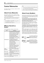
...IN Channels) All channel EQ settings All channel Pan settings All channel routings Fader groups, Mute groups, Fader group Masters, Mute group Masters, EQ links, and Compressor links All channel pair settings Effects parameters Effect programs recalled for Effects processors 1-4 and their parameter settings Remote Layer Fader and [ON] button status (only when Remote Control Target is a special read -only memory that contains the default settings of the Scene that the current settings on the 01V96i to USER DEFINED) Scene settings Scene titles and Fade Time settings Input Patching...
...IN Channels) All channel EQ settings All channel Pan settings All channel routings Fader groups, Mute groups, Fader group Masters, Mute group Masters, EQ links, and Compressor links All channel pair settings Effects parameters Effect programs recalled for Effects processors 1-4 and their parameter settings Remote Layer Fader and [ON] button status (only when Remote Control Target is a special read -only memory that contains the default settings of the Scene that the current settings on the 01V96i to USER DEFINED) Scene settings Scene titles and Fade Time settings Input Patching...
Reference Manual
Page 93
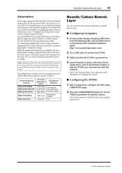
Note: Operating a fader also causes the Fader Touch command to be transmitted to Pro Tools. Download the Yamaha Steinberg USB Driver from the following URL, and install the driver as described in and out recording. Refer to the Nuendo/Cubase User's Manual for more information on the currently-selected Automation mode, the channel [SEL] button indicators operate as follows: User Defined Keys Function DAW AUTO WRITE DAW AUTO TOUTCH DAW AUTO LATCH DAW AUTO READ...
Note: Operating a fader also causes the Fader Touch command to be transmitted to Pro Tools. Download the Yamaha Steinberg USB Driver from the following URL, and install the driver as described in and out recording. Refer to the Nuendo/Cubase User's Manual for more information on the currently-selected Automation mode, the channel [SEL] button indicators operate as follows: User Defined Keys Function DAW AUTO WRITE DAW AUTO TOUTCH DAW AUTO LATCH DAW AUTO READ...
Reference Manual
Page 94
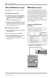
... assigned to General DAW. Bank Usage 1 Panning and setting GM sound levels 2 Setting GM sound effect send levels 3 Setting XG sound levels 4 Adjusting mute, and levels for more information on setting up the DAW software so that supports the Pro Tools protocol. ■ Configuring Computers 1. MIDI IN REC SONG SCENE MUSIC PRODUCTION SYNTHESIZER Integrated Sampling Sequencer Real-time External Control Sur face Modular Synthesis Plug-in these banks, which you can quickly recall to the MIDI IN port of a connected MIDI...
... assigned to General DAW. Bank Usage 1 Panning and setting GM sound levels 2 Setting GM sound effect send levels 3 Setting XG sound levels 4 Adjusting mute, and levels for more information on setting up the DAW software so that supports the Pro Tools protocol. ■ Configuring Computers 1. MIDI IN REC SONG SCENE MUSIC PRODUCTION SYNTHESIZER Integrated Sampling Sequencer Real-time External Control Sur face Modular Synthesis Plug-in these banks, which you can quickly recall to the MIDI IN port of a connected MIDI...

Reference Manual
Page 115
... 37 Compressor link 59 Linking 62 Contrast control 9 Control changes 100, 104 Control surface 6 AD input section 7 Channel strip section 7 Data entry section 9 DISPLAY ACCESS section 8 Display section 9 FADER MODE section 8 LAYER section 8 Monitor out & Headphones section 7 SCENE MEMORY section 9 SELECTED CHANNEL section ... 9 SOLO section 9 ST IN section 8 STEREO section 8 USER DEFINED KEYS section ..... 9 Control Surface & Rear Panel 6 COPY 15 Cursor buttons 9 D Data entry section 9 DAW 93 Nuendo/Cubase 93 Other 94 Pro tools 83 Remote 83 DEC & INC buttons 9 Delay...
... 37 Compressor link 59 Linking 62 Contrast control 9 Control changes 100, 104 Control surface 6 AD input section 7 Channel strip section 7 Data entry section 9 DISPLAY ACCESS section 8 Display section 9 FADER MODE section 8 LAYER section 8 Monitor out & Headphones section 7 SCENE MEMORY section 9 SELECTED CHANNEL section ... 9 SOLO section 9 ST IN section 8 STEREO section 8 USER DEFINED KEYS section ..... 9 Control Surface & Rear Panel 6 COPY 15 Cursor buttons 9 D Data entry section 9 DAW 93 Nuendo/Cubase 93 Other 94 Pro tools 83 Remote 83 DEC & INC buttons 9 Delay...

Reference Manual
Page 116
... button 96 Level controls 8 Levels 33, 38 LFE 56 Libraries 74 Channel library 75 Compressor library 79 Effects library 76 EQ library 81 Gate library 79 General operation 74 Input patch library 75 Output patch library 76 Link 59 Compressors 62 EQ 62 LOW button 9 LOW-MID button 9 M M.BAND DYNA 142 Machine control 98 MASTER button 8 Max 100 144 Meters Stereo meters 9 MIDI 84, 100 Bulk dump 107 Bulk dump messages 100 Control changes 104 Data format...
... button 96 Level controls 8 Levels 33, 38 LFE 56 Libraries 74 Channel library 75 Compressor library 79 Effects library 76 EQ library 81 Gate library 79 General operation 74 Input patch library 75 Output patch library 76 Link 59 Compressors 62 EQ 62 LOW button 9 LOW-MID button 9 M M.BAND DYNA 142 Machine control 98 MASTER button 8 Max 100 144 Meters Stereo meters 9 MIDI 84, 100 Bulk dump 107 Bulk dump messages 100 Control changes 104 Data format...

Reference Manual
Page 119
... Output Fader Group Assign X 67 Output Mute Group Assign X 68 Output EQ Group Assign X 69 Output COMP Group Assign X 70 Input Mute Group Master X 71 Output MUTE Group Master X 72 PEAK HOLD On/Off 73 OSCILLATOR On/Off 74 SOLO Enable 75 FADER/SOLO RELEASE Mode On/Off 76 Control Room Monitor MONO 77 Pan / Surround Link 78 Channel Name ID/Short 79 Channel Copy 80 Channel Paste 81 Display Back 82 Display Forward 83 UDEF KEYS BANK +1 84 UDEF KEYS BANK -1 85 UDEF KEYS BANK X 86 REMOTE USER...
... Output Fader Group Assign X 67 Output Mute Group Assign X 68 Output EQ Group Assign X 69 Output COMP Group Assign X 70 Input Mute Group Master X 71 Output MUTE Group Master X 72 PEAK HOLD On/Off 73 OSCILLATOR On/Off 74 SOLO Enable 75 FADER/SOLO RELEASE Mode On/Off 76 Control Room Monitor MONO 77 Pan / Surround Link 78 Channel Name ID/Short 79 Channel Copy 80 Channel Paste 81 Display Back 82 Display Forward 83 UDEF KEYS BANK +1 84 UDEF KEYS BANK -1 85 UDEF KEYS BANK X 86 REMOTE USER...


