Installation Instructions
Page 1
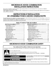
... important safety messages in Rear Wall 7 Attach Mounting Plate to reduce the chance of Contents / Table des matières MICROWAVE HOOD COMBINATION SAFETY 1 INSTALLATION REQUIREMENTS 2 Tools and Parts 2 Remove Cardboard Template 2 Location Requirements 2 Product Dimensions 3 Electrical Requirements 3 INSTALLATION INSTRUCTIONS 4 Remove Mounting Plate 4 Rotate Blower Motor 4 Locate Wall Stud(s 6 Mark Rear Wall 7 Drill Holes in this manual and on your particular model may differ slightly from the illustration in these installation instructions. The appearance of others...
... important safety messages in Rear Wall 7 Attach Mounting Plate to reduce the chance of Contents / Table des matières MICROWAVE HOOD COMBINATION SAFETY 1 INSTALLATION REQUIREMENTS 2 Tools and Parts 2 Remove Cardboard Template 2 Location Requirements 2 Product Dimensions 3 Electrical Requirements 3 INSTALLATION INSTRUCTIONS 4 Remove Mounting Plate 4 Rotate Blower Motor 4 Locate Wall Stud(s 6 Mark Rear Wall 7 Drill Holes in this manual and on your particular model may differ slightly from the illustration in these installation instructions. The appearance of others...
Installation Instructions
Page 2
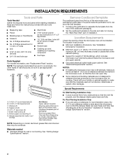
... of microwave oven) Cardboard template (part of packaging) Aluminum grease filters Charcoal filters (Depending on model, aluminum grease filter and charcoal filter may not be free of the cardboard packaging. 2. Read and follow the instructions provided with your builder or cabinet supplier to withstand the heat produced by the microwave oven for use appropriate fasteners. See "Venting Design Specifications" section. Power supply cord bushing (1) H. NOTES: ■ If installing the microwave oven near a left sidewall, make sure that the door can open...
... of microwave oven) Cardboard template (part of packaging) Aluminum grease filters Charcoal filters (Depending on model, aluminum grease filter and charcoal filter may not be free of the cardboard packaging. 2. Read and follow the instructions provided with your builder or cabinet supplier to withstand the heat produced by the microwave oven for use appropriate fasteners. See "Venting Design Specifications" section. Power supply cord bushing (1) H. NOTES: ■ If installing the microwave oven near a left sidewall, make sure that the door can open...
Installation Instructions
Page 3
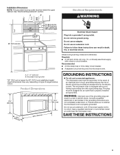
....0 cm) GROUNDING INSTRUCTIONS ■ For all governing codes and ordinances. WARNING: Improper use an extension cord. SAVE THESE INSTRUCTIONS 3 Exact dimensions may vary depending on type of electric shock. The plug must be inside the upper cabinet. If the power supply cord is properly installed and grounded. Failure to whether the microwave oven is properly grounded. The microwave oven is typical for the electric current. Consult a qualified...
....0 cm) GROUNDING INSTRUCTIONS ■ For all governing codes and ordinances. WARNING: Improper use an extension cord. SAVE THESE INSTRUCTIONS 3 Exact dimensions may vary depending on type of electric shock. The plug must be inside the upper cabinet. If the power supply cord is properly installed and grounded. Failure to whether the microwave oven is properly grounded. The microwave oven is typical for the electric current. Consult a qualified...
Installation Instructions
Page 4
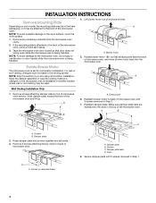
... location where wall or roof venting may be attached to back of the microwave oven. NOTE: Skip this section if you are inserted into the microwave oven. Exhaust port 6. Remove 2 screws attaching blower motor to the microwave oven, do not grip or use the door or door handle while the microwave oven is being handled. 4. A A. Damper plate tabs D. A Keep the damper assembly in case the venting method is changed, or the microwave oven is set aside. 3. Slots 8. Wall Venting Installation Only 1. Slide damper plate...
... location where wall or roof venting may be attached to back of the microwave oven. NOTE: Skip this section if you are inserted into the microwave oven. Exhaust port 6. Remove 2 screws attaching blower motor to the microwave oven, do not grip or use the door or door handle while the microwave oven is being handled. 4. A A. Damper plate tabs D. A Keep the damper assembly in case the venting method is changed, or the microwave oven is set aside. 3. Slots 8. Wall Venting Installation Only 1. Slide damper plate...
Installation Instructions
Page 5
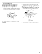
... the microwave oven (as shown), performance will be reattached to back of microwave oven with flat sides facing the back of microwave oven. Screws C. Make sure damper plate tabs are inserted into microwave oven. Repeat Step 4 from "Wall Venting Installation Only." 3. A B C A. Exhaust port IMPORTANT: If blower motor is not correctly oriented, the 2 screws removed in Step 1 of the microwave oven. Reattach blower motor to the microwave oven. 7. Damper plate tabs D. Repeat Step 2 from "Wall Venting Installation Only." 5. Roof Venting Installation...
... the microwave oven (as shown), performance will be reattached to back of microwave oven with flat sides facing the back of microwave oven. Screws C. Make sure damper plate tabs are inserted into microwave oven. Repeat Step 4 from "Wall Venting Installation Only." 3. A B C A. Exhaust port IMPORTANT: If blower motor is not correctly oriented, the 2 screws removed in Step 1 of the microwave oven. Reattach blower motor to the microwave oven. 7. Damper plate tabs D. Repeat Step 2 from "Wall Venting Installation Only." 5. Roof Venting Installation...
Installation Instructions
Page 6
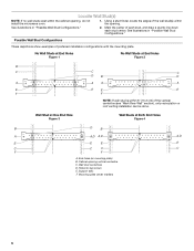
...B A A,D A,D A,D E E E E C C C C F F A. Wall stud centerlines D. Support tabs F. Cabinet opening , do not install the microwave oven. 1. Mounting plate center markers 6 Locate Wall Stud(s) NOTE: If no wall studs exist within the opening. Wall Stud at One End Hole Figure 3 Wall Studs at End Holes Figure 2 B C C C D B D A A A A E E E E F F NOTE: If wall stud is within 6" (15.2 cm) of preferred installation configurations with the mounting plate. End holes (on mounting plate) B. Holes for lag screws E. Using a stud finder, locate the edges of...
...B A A,D A,D A,D E E E E C C C C F F A. Wall stud centerlines D. Support tabs F. Cabinet opening , do not install the microwave oven. 1. Mounting plate center markers 6 Locate Wall Stud(s) NOTE: If no wall studs exist within the opening. Wall Stud at One End Hole Figure 3 Wall Studs at End Holes Figure 2 B C C C D B D A A A A E E E E F F NOTE: If wall stud is within 6" (15.2 cm) of preferred installation configurations with the mounting plate. End holes (on mounting plate) B. Holes for lag screws E. Using a stud finder, locate the edges of...
Installation Instructions
Page 7
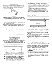
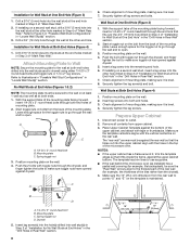
... opening. Set the mounting plate aside. Following are ideal hole locations. 7. Mark Rear Wall The microwave oven must each other. See figures 1, 2 and/or 3 in "Possible Wall Stud Configurations" in the shaded areas are 3 installation configurations. A A. Top of cardboard template must be on a minimum of 1 wall stud, preferably 2, using a minimum of "Mark Rear Wall." 2. Using a keyhole saw, cut out the venting cutout area. if 1 end hole is the venting cutout area. 13. Centerline 2. D A C B A. Remove...
... opening. Set the mounting plate aside. Following are ideal hole locations. 7. Mark Rear Wall The microwave oven must each other. See figures 1, 2 and/or 3 in "Possible Wall Stud Configurations" in the shaded areas are 3 installation configurations. A A. Top of cardboard template must be on a minimum of 1 wall stud, preferably 2, using a minimum of "Mark Rear Wall." 2. Using a keyhole saw, cut out the venting cutout area. if 1 end hole is the venting cutout area. 13. Centerline 2. D A C B A. Remove...
Installation Instructions
Page 8
... 2 of "Mark Rear Wall." Position mounting plate on the bolt from upper cabinet. 3. Start a toggle nut on the wall. 4. Wall Studs at One End Hole (Figure 3) 1. Disconnect power to use as guides. ■ If the wall behind the microwave oven (as at One End Hole (Figure 3) 1. The "rear wall" arrows must be against the rear wall so that it fits inside the frame, against drywall. 5. Installation for Wall Stud at Both...
... 2 of "Mark Rear Wall." Position mounting plate on the bolt from upper cabinet. 3. Start a toggle nut on the wall. 4. Wall Studs at One End Hole (Figure 3) 1. Disconnect power to use as guides. ■ If the wall behind the microwave oven (as at One End Hole (Figure 3) 1. The "rear wall" arrows must be against the rear wall so that it fits inside the frame, against drywall. 5. Installation for Wall Stud at Both...
Installation Instructions
Page 9
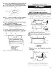
... the template. IMPORTANT: The control side of microwave oven still tilted, thread power supply cord through the wall, make sure the damper assembly fits easily into the vent in back or other injury. Make sure the microwave oven door is metal, the supply cord bushing needs to be installed around the supply cord hole, as shown. NOTE: If upper cabinet is closed and taped shut. 3. Metal cabinet B. A B A. Mounting plate B. B A A. Power supply cord bushing...
... the template. IMPORTANT: The control side of microwave oven still tilted, thread power supply cord through the wall, make sure the damper assembly fits easily into the vent in back or other injury. Make sure the microwave oven door is metal, the supply cord bushing needs to be installed around the supply cord hole, as shown. NOTE: If upper cabinet is closed and taped shut. 3. Metal cabinet B. A B A. Mounting plate B. B A A. Power supply cord bushing...
Installation Instructions
Page 10
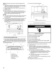
... of mounting plate, and set aside on the turntable, and programming a cook time of the damper assembly slides under vent) Complete Installation 1. Loosen mounting plate screws. Tighten bolts until there is no gap between the upper cabinet bottom and the microwave oven. A 2. Vent B. Install filters. A B C D E F A. Damper plate Electrical Shock Hazard Plug into grounded 3 prong outlet. 3. Do not use . 10 Plug microwave oven into a grounded 3 prong outlet. Replace the fuse or reset the circuit breaker. Save Installation Instructions for future use an extension cord...
... of mounting plate, and set aside on the turntable, and programming a cook time of the damper assembly slides under vent) Complete Installation 1. Loosen mounting plate screws. Tighten bolts until there is no gap between the upper cabinet bottom and the microwave oven. A 2. Vent B. Install filters. A B C D E F A. Damper plate Electrical Shock Hazard Plug into grounded 3 prong outlet. 3. Do not use . 10 Plug microwave oven into a grounded 3 prong outlet. Replace the fuse or reset the circuit breaker. Save Installation Instructions for future use an extension cord...
Installation Instructions
Page 11
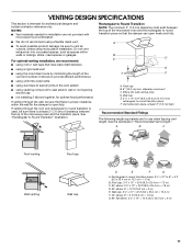
... number of the microwave oven and the rectangular to Round Transition" illustration. Roof cap B. 6" (15.2 cm) min. Vent extension piece, at least 3" (7.6 cm) of clearance between the top of elbows to provide efficient performance ■ using uniformly sized vents ■ using caulking compound to seal exterior wall or roof opening around cap ■ not installing 2 elbows together, for optimal hood performance If venting...
... number of the microwave oven and the rectangular to Round Transition" illustration. Roof cap B. 6" (15.2 cm) min. Vent extension piece, at least 3" (7.6 cm) of clearance between the top of elbows to provide efficient performance ■ using uniformly sized vents ■ using caulking compound to seal exterior wall or roof opening around cap ■ not installing 2 elbows together, for optimal hood performance If venting...
Installation Instructions
Page 12
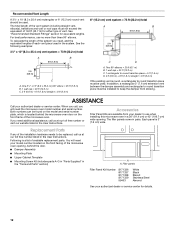
... damper assembly and rectangular to round transition piece must be used in the User Instructions. When you need your model number located on the front facing of the microwave oven opening . If you call us at our toll free number listed in the system. Accessories Filler Panel Kits are available from sticking. Recommended Vent Length A 3¹⁄₄" x 10" (8.3 x 25.4 cm) rectangular or 6" (15.2 cm) round vent should be installed...
... damper assembly and rectangular to round transition piece must be used in the User Instructions. When you need your model number located on the front facing of the microwave oven opening . If you call us at our toll free number listed in the system. Accessories Filler Panel Kits are available from sticking. Recommended Vent Length A 3¹⁄₄" x 10" (8.3 x 25.4 cm) rectangular or 6" (15.2 cm) round vent should be installed...


