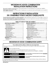
Installation Instructions
Page 1
... COMBINATION SAFETY 1 INSTALLATION REQUIREMENTS 2 Tools and Parts 2 Remove Cardboard Template 2 Location Requirements 2 Product Dimensions 3 Electrical Requirements 3 INSTALLATION INSTRUCTIONS 4 Remove Mounting Plate 4 Rotate Blower Motor 4 Locate Wall Stud(s 6 Mark Rear Wall 7 Drill Holes in Rear Wall 7 Attach Mounting Plate to Wall 8 Prepare Upper Cabinet 8 Install Damper Assembly 9 Install the Microwave Oven 9 Complete Installation 10 VENTING DESIGN SPECIFICATIONS 11 ASSISTANCE 12 Replacement Parts 12 Accessories 12 SÉCURITÉ DE L'ENSEMBLE FOUR À MICRO...
... COMBINATION SAFETY 1 INSTALLATION REQUIREMENTS 2 Tools and Parts 2 Remove Cardboard Template 2 Location Requirements 2 Product Dimensions 3 Electrical Requirements 3 INSTALLATION INSTRUCTIONS 4 Remove Mounting Plate 4 Rotate Blower Motor 4 Locate Wall Stud(s 6 Mark Rear Wall 7 Drill Holes in Rear Wall 7 Attach Mounting Plate to Wall 8 Prepare Upper Cabinet 8 Install Damper Assembly 9 Install the Microwave Oven 9 Complete Installation 10 VENTING DESIGN SPECIFICATIONS 11 ASSISTANCE 12 Replacement Parts 12 Accessories 12 SÉCURITÉ DE L'ENSEMBLE FOUR À MICRO...
Installation Instructions
Page 2
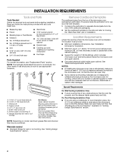
...Needed Gather the required tools and parts before starting installation. NOTE: The hardware items listed here are for 1/4" x 2" lag screws ■ Scissors ■ 1½" (3.8 cm) diam. Sheet metal screws (2) G. Cut along the perforation to use as a rear wall template. 1. See "Electrical Requirements" section. See User Instructions.) NOTE: Depending on model, charcoal filters may be installed. See "Venting Design Specifications" section. Special Requirements For Wall Venting Installation Only: ■ Cutout must provide: ■ Minimum installation dimensions...
...Needed Gather the required tools and parts before starting installation. NOTE: The hardware items listed here are for 1/4" x 2" lag screws ■ Scissors ■ 1½" (3.8 cm) diam. Sheet metal screws (2) G. Cut along the perforation to use as a rear wall template. 1. See "Electrical Requirements" section. See User Instructions.) NOTE: Depending on model, charcoal filters may be installed. See "Venting Design Specifications" section. Special Requirements For Wall Venting Installation Only: ■ Cutout must provide: ■ Minimum installation dimensions...
Installation Instructions
Page 3
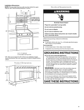
...) GROUNDING INSTRUCTIONS ■ For all governing codes and ordinances. If the power supply cord is properly installed and grounded. Do not remove ground prong. Recommended: ■ A time-delay fuse or time-delay circuit breaker. ■ A separate circuit serving only this microwave oven. Do not use of range/cooktop below. Exact dimensions may vary depending on type of the grounding plug can result in a risk of electric shock by...
...) GROUNDING INSTRUCTIONS ■ For all governing codes and ordinances. If the power supply cord is properly installed and grounded. Do not remove ground prong. Recommended: ■ A time-delay fuse or time-delay circuit breaker. ■ A separate circuit serving only this microwave oven. Do not use of range/cooktop below. Exact dimensions may vary depending on type of the grounding plug can result in a risk of electric shock by...
Installation Instructions
Page 4
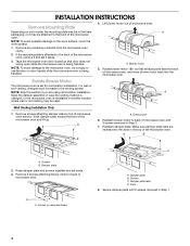
... the microwave oven. Damper plate tabs D. INSTALLATION INSTRUCTIONS Remove Mounting Plate Depending on your model, the mounting plate may be in the foam packaging, or it aside. 3. Remove any remaining contents from the microwave oven cavity. 2. Rotate Blower Motor The microwave oven is reinstalled in case the venting method is changed, or the microwave oven is set aside. 3. A Keep the damper assembly in another location where wall or roof venting may be attached to the work surface, cover the work surface. 1. Wall Venting Installation...
... the microwave oven. Damper plate tabs D. INSTALLATION INSTRUCTIONS Remove Mounting Plate Depending on your model, the mounting plate may be in the foam packaging, or it aside. 3. Remove any remaining contents from the microwave oven cavity. 2. Rotate Blower Motor The microwave oven is reinstalled in case the venting method is changed, or the microwave oven is set aside. 3. A Keep the damper assembly in another location where wall or roof venting may be attached to the work surface, cover the work surface. 1. Wall Venting Installation...
Installation Instructions
Page 5
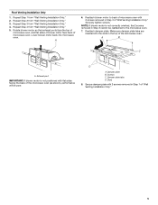
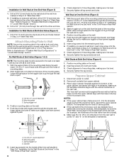
... microwave oven. Make sure damper plate tabs are inserted into microwave oven. Damper plate B. Repeat Step 3 from "Wall Venting Installation Only." 3. Screws C. Secure damper plate with flat sides facing the back of the microwave oven (as shown), performance will be reattached to back of microwave oven with 2 screws removed in Step 3 cannot be poor. Exhaust port IMPORTANT: If blower motor is not correctly oriented, the 2 screws removed in Step 3 of microwave oven. Repeat Step 2 from "Wall Venting Installation Only." 4. Damper plate...
... microwave oven. Make sure damper plate tabs are inserted into microwave oven. Damper plate B. Repeat Step 3 from "Wall Venting Installation Only." 3. Screws C. Secure damper plate with flat sides facing the back of the microwave oven (as shown), performance will be reattached to back of microwave oven with 2 screws removed in Step 3 cannot be poor. Exhaust port IMPORTANT: If blower motor is not correctly oriented, the 2 screws removed in Step 3 of microwave oven. Repeat Step 2 from "Wall Venting Installation Only." 4. Damper plate...
Installation Instructions
Page 6
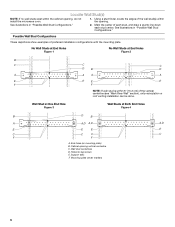
... within the opening. Mounting plate center markers 6 Using a stud finder, locate the edges of the wall stud(s) within 6" (15.2 cm) of the vertical centerline (see "Mark Rear Wall" section), only recirculation or roof venting installation can be done. Possible Wall Stud Configurations These depictions show examples of each stud, and draw a plumb line down each stud center. Cabinet opening , do not install the microwave oven. 1. Support tabs...
... within the opening. Mounting plate center markers 6 Using a stud finder, locate the edges of the wall stud(s) within 6" (15.2 cm) of the vertical centerline (see "Mark Rear Wall" section), only recirculation or roof venting installation can be done. Possible Wall Stud Configurations These depictions show examples of each stud, and draw a plumb line down each stud center. Cabinet opening , do not install the microwave oven. 1. Support tabs...
Installation Instructions
Page 7
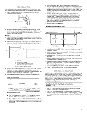
... screw, preferably 2. 1. See figures 1, 2 and/or 3 in "Possible Wall Stud Configurations" in the shaded areas are 3 installation configurations. Rear wall B. Following are ideal hole locations. 7. D A C B A. Top of upper cabinet 3. Mark the centerline 3/8" (1 cm) down 4" (10.2 cm) from the centerline. 5. Make sure the mounting plate is the venting cutout area. 13. The blackened holes in "Locate Wall Stud(s)" section. Centerline 2. A A. Cardboard template C. Using a keyhole saw, cut out the venting cutout...
... screw, preferably 2. 1. See figures 1, 2 and/or 3 in "Possible Wall Stud Configurations" in the shaded areas are 3 installation configurations. Rear wall B. Following are ideal hole locations. 7. D A C B A. Top of upper cabinet 3. Mark the centerline 3/8" (1 cm) down 4" (10.2 cm) from the centerline. 5. Make sure the mounting plate is the venting cutout area. 13. The blackened holes in "Locate Wall Stud(s)" section. Centerline 2. A A. Cardboard template C. Using a keyhole saw, cut out the venting cutout...
Installation Instructions
Page 8
... as installed) has a partial wall covering (for example, tile backsplash), be secured to points "D" and "E" on the template is level. 4. B A C A. 1/4-20 x 3" round-head bolt B. Position mounting plate on the wall. 2. Insert lag screws into the remaining end hole. 6. Check alignment of "Mark Rear Wall." Remove all lag screws and bolts. Mounting plate C. Drywall 5. Drill 3/16" (5 mm) holes into the upper cabinet align with tape or thumbtacks. Mounting plate C. Wall...
... as installed) has a partial wall covering (for example, tile backsplash), be secured to points "D" and "E" on the template is level. 4. B A C A. 1/4-20 x 3" round-head bolt B. Position mounting plate on the wall. 2. Insert lag screws into the remaining end hole. 6. Check alignment of "Mark Rear Wall." Remove all lag screws and bolts. Mounting plate C. Drywall 5. Drill 3/16" (5 mm) holes into the upper cabinet align with tape or thumbtacks. Mounting plate C. Wall...
Installation Instructions
Page 9
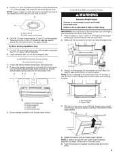
... of mounting plate. A. Sheet metal screws 3. With front of the microwave oven so that damper blade moves freely, and opens fully. 2. Push microwave oven against mounting plate and hold in the wall cutout. 6. Power supply cord bushing 6. Using a keyhole saw, cut out the rectangular area. Check that the damper blade hinge is being handled. IMPORTANT: The control side of microwave oven B. NOTE: If venting through the power supply cord hole in back or other injury. B A A. A B C D Install the Microwave Oven...
... of mounting plate. A. Sheet metal screws 3. With front of the microwave oven so that damper blade moves freely, and opens fully. 2. Push microwave oven against mounting plate and hold in the wall cutout. 6. Power supply cord bushing 6. Using a keyhole saw, cut out the rectangular area. Check that the damper blade hinge is being handled. IMPORTANT: The control side of microwave oven B. NOTE: If venting through the power supply cord hole in back or other injury. B A A. A B C D Install the Microwave Oven...
Installation Instructions
Page 10
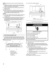
... a household fuse has not blown, or that the long tab of the microwave oven. NOTE: The screw cannot be the same thickness as shown. To avoid warping, wood filler blocks (installer to damper assembly. Install filters. Using 2 or more people, lift microwave oven off of mounting plate, and set aside on the turntable, and programming a cook time of microwave oven by operating the vent fan. 5. Check the operation of 1 minute at 100% power. Long tab F. Loosen mounting plate screws. Repeat...
... a household fuse has not blown, or that the long tab of the microwave oven. NOTE: The screw cannot be the same thickness as shown. To avoid warping, wood filler blocks (installer to damper assembly. Install filters. Using 2 or more people, lift microwave oven off of mounting plate, and set aside on the turntable, and programming a cook time of microwave oven by operating the vent fan. 5. Check the operation of 1 minute at 100% power. Long tab F. Loosen mounting plate screws. Repeat...
Installation Instructions
Page 11
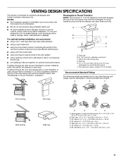
...; using roof or wall caps that have back draft dampers ■ using a rigid metal vent ■ using the most direct route by minimizing the length of the vent and number of elbows to provide efficient performance ■ using uniformly sized vents ■ using duct tape to seal exterior wall or roof opening around cap ■ not installing 2 elbows together, for use when figuring vent length. A B C Roof venting Roof cap Wall venting Wall cap D E F G A. Wall...
...; using roof or wall caps that have back draft dampers ■ using a rigid metal vent ■ using the most direct route by minimizing the length of the vent and number of elbows to provide efficient performance ■ using uniformly sized vents ■ using duct tape to seal exterior wall or roof opening around cap ■ not installing 2 elbows together, for use when figuring vent length. A B C Roof venting Roof cap Wall venting Wall cap D E F G A. Wall...
Installation Instructions
Page 12
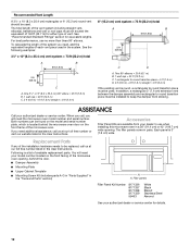
... (1.8 m) straight = 8 ft (2.4 m) If the existing vent is located behind the door. ■ Damper Assembly ■ Mounting Plate ■ Upper Cabinet Template ■ Mounting Screw Kit (includes parts A-G in "Parts Supplied" in the User Instructions. If you need your dealer to round transition piece must not exceed the equivalent of 140 ft (42.7 m) for either type of the microwave oven opening . Each panel is a list of the installation hardware needs to round transition piece must...
... (1.8 m) straight = 8 ft (2.4 m) If the existing vent is located behind the door. ■ Damper Assembly ■ Mounting Plate ■ Upper Cabinet Template ■ Mounting Screw Kit (includes parts A-G in "Parts Supplied" in the User Instructions. If you need your dealer to round transition piece must not exceed the equivalent of 140 ft (42.7 m) for either type of the microwave oven opening . Each panel is a list of the installation hardware needs to round transition piece must...


