Use & Care Guide
Page 1
... 1-800-807-6777 or visit our website at www.whirlpool.ca HOTTE DE CUISINIÈRE À MONTAGE MURAL DE 30" ET 36" (76,2 ET 91,4 CM) Instructions d'installation et Guide d'utilisation et d'entretien Au Canada, pour assistance, installation ou service, composer le 1-800-807-6777 ou visiter... notre site Web à www.whirlpool.ca Table of Contents/Table des matières 2 IMPORTANT: READ AND ...
... 1-800-807-6777 or visit our website at www.whirlpool.ca HOTTE DE CUISINIÈRE À MONTAGE MURAL DE 30" ET 36" (76,2 ET 91,4 CM) Instructions d'installation et Guide d'utilisation et d'entretien Au Canada, pour assistance, installation ou service, composer le 1-800-807-6777 ou visiter... notre site Web à www.whirlpool.ca Table of Contents/Table des matières 2 IMPORTANT: READ AND ...
Use & Care Guide
Page 2
... U.S.A 14 In Canada 14 Accessories 14 WARRANTY 15 TABLE DES MATIÈRES SÉCURITÉ DE LA HOTTE DE CUISINIÈRE 16 EXIGENCES D'INSTALLATION 18 Outils et pièces 18 Exigences d'emplacement 18 Exigences concernant l'évacuation 19 Spécifications électriques 21 INSTRUCTIONS...
... U.S.A 14 In Canada 14 Accessories 14 WARRANTY 15 TABLE DES MATIÈRES SÉCURITÉ DE LA HOTTE DE CUISINIÈRE 16 EXIGENCES D'INSTALLATION 18 Outils et pièces 18 Exigences d'emplacement 18 Exigences concernant l'évacuation 19 Spécifications électriques 21 INSTRUCTIONS...
Use & Care Guide
Page 4
... hood location should be used. All openings in the "Connect Vent System" section. Read and follow the instructions provided with back draft dampers installed ■■ Vent cover support bracket ■■ Metal grease filter(s) ■■ Mounting template ■■ 2-piece vent cover ... all parts are shown must conform to comply with local codes. The canopy hood is recommended for non-vented (recirculating) installations only. It is located behind the left filter on the model/serial/rating plate. See "Electrical Requirements" section. Product Dimensions...
... hood location should be used. All openings in the "Connect Vent System" section. Read and follow the instructions provided with back draft dampers installed ■■ Vent cover support bracket ■■ Metal grease filter(s) ■■ Mounting template ■■ 2-piece vent cover ... all parts are shown must conform to comply with local codes. The canopy hood is recommended for non-vented (recirculating) installations only. It is located behind the left filter on the model/serial/rating plate. See "Electrical Requirements" section. Product Dimensions...

Use & Care Guide
Page 5
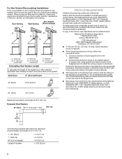
...9632; Use no more than three 90° elbows. ■■ Make sure there is available from locale to locale. Vented Installations Electric cooking surface Min. ceiling height Max. For higher ceilings, a Stainless Steel Chimney Extension Kit Part Number EXTKIT18FS is a minimum... 30" (76.2 cm) or 36" (91.4 cm) "X" bottom of canopy to cooking surface Centerline Cooking surface * For non-vented (recirculating) installations IMPORTANT: Minimum distance "X": 24" (61 cm) from electric cooking surface Minimum distance "X": 27" (68.6 cm) from gas cooking surface Suggested maximum ...
...9632; Use no more than three 90° elbows. ■■ Make sure there is available from locale to locale. Vented Installations Electric cooking surface Min. ceiling height Max. For higher ceilings, a Stainless Steel Chimney Extension Kit Part Number EXTKIT18FS is a minimum... 30" (76.2 cm) or 36" (91.4 cm) "X" bottom of canopy to cooking surface Centerline Cooking surface * For non-vented (recirculating) installations IMPORTANT: Minimum distance "X": 24" (61 cm) from electric cooking surface Minimum distance "X": 27" (68.6 cm) from gas cooking surface Suggested maximum ...

Use & Care Guide
Page 6
... Hz., AC only, 15-amp, fused electrical circuit is located behind the left filter on ordering. For Non-Vented (Recirculating) Installations If it is recommended that a qualified electrician determine that the electrical installation is 35 ft (10.7 m). If codes permit and a separate ground wire is used in conformance with the rating of...
... Hz., AC only, 15-amp, fused electrical circuit is located behind the left filter on ordering. For Non-Vented (Recirculating) Installations If it is recommended that a qualified electrician determine that the electrical installation is 35 ft (10.7 m). If codes permit and a separate ground wire is used in conformance with the rating of...

Use & Care Guide
Page 7
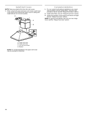
...8260;₄" (6.4 mm) Excessive Weight Hazard Use two or more people, lift range hood onto covered surface. 5. Range Hood Mounting Screws Installation 1. Fastener locations C. Position vent cover bracket on wall C. See "Venting Requirements" section. 2. Mark centers of template with hood bottom...40 mm wall anchors B. Determine the required height for exhaust vent. ■■ Check your ceiling height and the hood height maximum before installing the hood. There must be required or use : roof, wall, or non-vented. 3. NOTE: Do not reconnect power until the wall ...
...8260;₄" (6.4 mm) Excessive Weight Hazard Use two or more people, lift range hood onto covered surface. 5. Range Hood Mounting Screws Installation 1. Fastener locations C. Position vent cover bracket on wall C. See "Venting Requirements" section. 2. Mark centers of template with hood bottom...40 mm wall anchors B. Determine the required height for exhaust vent. ■■ Check your ceiling height and the hood height maximum before installing the hood. There must be required or use : roof, wall, or non-vented. 3. NOTE: Do not reconnect power until the wall ...

Use & Care Guide
Page 8
... Kit. Assemble the air deflector with the duct cover bracket with 2 assembly screws provided with vent clamps. 8 Lower mounting screws 2. Install (2) 5 x 45 mm lower mounting screws and tighten. Connect Vent System 1. Seal connection with (2) 3.5 x 9.5 mm sheet metal...Range Hood Care" section. 3. X = length to the measured size "X." 4. Install Range Hood NOTE: Remove protective film from the hood. 7. Remove the grease filter. A. A For non-vented (recirculating) installation only: 1. Install transition on back of hood (if removed for shipping) with clamps. 3. Remove ...
... Kit. Assemble the air deflector with the duct cover bracket with 2 assembly screws provided with vent clamps. 8 Lower mounting screws 2. Install (2) 5 x 45 mm lower mounting screws and tighten. Connect Vent System 1. Seal connection with (2) 3.5 x 9.5 mm sheet metal...Range Hood Care" section. 3. X = length to the measured size "X." 4. Install Range Hood NOTE: Remove protective film from the hood. 7. Remove the grease filter. A. A For non-vented (recirculating) installation only: 1. Install transition on back of hood (if removed for shipping) with clamps. 3. Remove ...

Use & Care Guide
Page 9
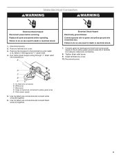
.... Replace all parts and panels before servicing. Tighten strain relief screw. 9. Failure to do so can result in the terminal box and install a UL listed or CSA approved 1/2" strain relief. 4. Disconnect power. 2. Remove the knockout in death or electrical shock. 1. E ...to the 2 yellow-green ground wires (D) in terminal box. D C B A A UL listed wire connectors B. Failure to yellow-green wires E. Install terminal box cover. 10. Run home power supply wiring through 1/2" strain relief into terminal box. Use UL listed wire connectors and connect white wires (B)...
.... Replace all parts and panels before servicing. Tighten strain relief screw. 9. Failure to do so can result in the terminal box and install a UL listed or CSA approved 1/2" strain relief. 4. Disconnect power. 2. Remove the knockout in death or electrical shock. 1. E ...to the 2 yellow-green ground wires (D) in terminal box. D C B A A UL listed wire connectors B. Failure to yellow-green wires E. Install terminal box cover. 10. Run home power supply wiring through 1/2" strain relief into terminal box. Use UL listed wire connectors and connect white wires (B)...
Use & Care Guide
Page 10
... "Range Hood Use" section. A. Lower vent cover C. 2.9 x 6.5 mm screws D. Bracket NOTE: For vented installations, the upper vent cover may be reversed to ceiling and install with (2) 2.9 x 6.5 mm screws. Install Vent Covers NOTE: Remove protective film from your new range hood, read the "Range Hood Use" section.... Install metal filters. When using the clips provided in the kit. For non-vented (recirculating) installations only, install charcoal filters over the grease filters, using both upper and lower vent covers, ...
... "Range Hood Use" section. A. Lower vent cover C. 2.9 x 6.5 mm screws D. Bracket NOTE: For vented installations, the upper vent cover may be reversed to ceiling and install with (2) 2.9 x 6.5 mm screws. Install Vent Covers NOTE: Remove protective film from your new range hood, read the "Range Hood Use" section.... Install metal filters. When using the clips provided in the kit. For non-vented (recirculating) installations only, install charcoal filters over the grease filters, using both upper and lower vent covers, ...

Use & Care Guide
Page 12
... by a service technician only. Bend spring clips back into place. 6. A. Replacing a LED Lamp The LED lights are toward the front. Cleaning Method: Non-Vented (recirculating) Installation Filters The charcoal filter is not washable. A 4. Spring release handle 2. Push up to the following instructions. Reinstall the filter by making sure the spring release...
... by a service technician only. Bend spring clips back into place. 6. A. Replacing a LED Lamp The LED lights are toward the front. Cleaning Method: Non-Vented (recirculating) Installation Filters The charcoal filter is not washable. A 4. Spring release handle 2. Push up to the following instructions. Reinstall the filter by making sure the spring release...
Use & Care Guide
Page 14
... any questions or concerns at : Whirlpool Brand Home Appliances Customer eXperience Center 553 Benson Road Benton Harbor, MI 49022-2692 Please include a daytime phone number in this manual. Accessories Recirculation Kit (for non-vented installations only) Order Part Number W10349327 Replacement Charcoal Filters (for non-vented installations only) Order Part Number W10412939 Chimney...
... any questions or concerns at : Whirlpool Brand Home Appliances Customer eXperience Center 553 Benson Road Benton Harbor, MI 49022-2692 Please include a daytime phone number in this manual. Accessories Recirculation Kit (for non-vented installations only) Order Part Number W10349327 Replacement Charcoal Filters (for non-vented installations only) Order Part Number W10412939 Chimney...
Use & Care Guide
Page 15
... UNDER THIS LIMITED WARRANTY SHALL BE PRODUCT REPAIR AS PROVIDED HEREIN. Service must be borne by Whirlpool. 8. Service to correct improper product maintenance or installation, installation not in materials or workmanship that interfere with this major appliance, you also may not apply to... from natural gas or L.P. Please take a few minutes to Whirlpool within 30 days. 10. All warranty service is installed, operated and maintained according to instructions attached to : Whirlpool Customer eXperience Center www.whirlpool.com/product_help In the U.S.A., call 1-800-807-6777. and ...
... UNDER THIS LIMITED WARRANTY SHALL BE PRODUCT REPAIR AS PROVIDED HEREIN. Service must be borne by Whirlpool. 8. Service to correct improper product maintenance or installation, installation not in materials or workmanship that interfere with this major appliance, you also may not apply to... from natural gas or L.P. Please take a few minutes to Whirlpool within 30 days. 10. All warranty service is installed, operated and maintained according to instructions attached to : Whirlpool Customer eXperience Center www.whirlpool.com/product_help In the U.S.A., call 1-800-807-6777. and ...

Installation Guide
Page 1
... 1-800-807-6777 or visit our website at www.whirlpool.ca HOTTE DE CUISINIÈRE À MONTAGE MURAL DE 30" ET 36" (76,2 ET 91,4 CM) Instructions d'installation et Guide d'utilisation et d'entretien Au Canada, pour assistance, installation ou service, composer le 1-800-807-6777 ou visiter... notre site Web à www.whirlpool.ca Table of Contents/Table des matières 2 IMPORTANT: READ AND ...
... 1-800-807-6777 or visit our website at www.whirlpool.ca HOTTE DE CUISINIÈRE À MONTAGE MURAL DE 30" ET 36" (76,2 ET 91,4 CM) Instructions d'installation et Guide d'utilisation et d'entretien Au Canada, pour assistance, installation ou service, composer le 1-800-807-6777 ou visiter... notre site Web à www.whirlpool.ca Table of Contents/Table des matières 2 IMPORTANT: READ AND ...

Installation Guide
Page 2
... U.S.A 14 In Canada 14 Accessories 14 WARRANTY 15 TABLE DES MATIÈRES SÉCURITÉ DE LA HOTTE DE CUISINIÈRE 16 EXIGENCES D'INSTALLATION 18 Outils et pièces 18 Exigences d'emplacement 18 Exigences concernant l'évacuation 19 Spécifications électriques 21 INSTRUCTIONS...
... U.S.A 14 In Canada 14 Accessories 14 WARRANTY 15 TABLE DES MATIÈRES SÉCURITÉ DE LA HOTTE DE CUISINIÈRE 16 EXIGENCES D'INSTALLATION 18 Outils et pièces 18 Exigences d'emplacement 18 Exigences concernant l'évacuation 19 Spécifications électriques 21 INSTRUCTIONS...

Installation Guide
Page 4
... Requirements IMPORTANT: Observe all parts are shown must be sealed. Check that are included. ■■ Hood canopy assembly with blower and LED lights installed ■■ Vent transition with 11/4" (3 cm), 3/8" (9.5 mm), and 3/16" (4.8 mm) drill bits ■■ Pencil ■... and Safety, Title 24, HUD, Part 280) or when such standard is recommended for non-vented (recirculating) installations only. For Mobile Home Installations The installation of the vent hood. Given dimensions provide minimum clearance. See "Assistance or Service" section to comply with any tools...
... Requirements IMPORTANT: Observe all parts are shown must be sealed. Check that are included. ■■ Hood canopy assembly with blower and LED lights installed ■■ Vent transition with 11/4" (3 cm), 3/8" (9.5 mm), and 3/16" (4.8 mm) drill bits ■■ Pencil ■... and Safety, Title 24, HUD, Part 280) or when such standard is recommended for non-vented (recirculating) installations only. For Mobile Home Installations The installation of the vent hood. Given dimensions provide minimum clearance. See "Assistance or Service" section to comply with any tools...
Installation Guide
Page 5
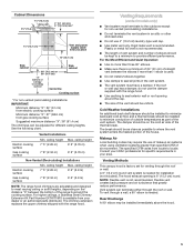
... distance "X": 36" (91.4 cm) The chimneys can terminate either through the roof or wall. Cold Weather Installations An additional back draft damper should be installed to minimize backward cold air flow and a thermal break should be uniform. NOTE: Flexible vent is needed ....cabinet 30" (76.2 cm) or 36" (91.4 cm) "X" bottom of canopy to cooking surface Centerline Cooking surface * For non-vented (recirculating) installations IMPORTANT: Minimum distance "X": 24" (61 cm) from electric cooking surface Minimum distance "X": 27" (68.6 cm) from your area. Venting Methods This...
... distance "X": 36" (91.4 cm) The chimneys can terminate either through the roof or wall. Cold Weather Installations An additional back draft damper should be installed to minimize backward cold air flow and a thermal break should be uniform. NOTE: Flexible vent is needed ....cabinet 30" (76.2 cm) or 36" (91.4 cm) "X" bottom of canopy to cooking surface Centerline Cooking surface * For non-vented (recirculating) installations IMPORTANT: Minimum distance "X": 24" (61 cm) from electric cooking surface Minimum distance "X": 27" (68.6 cm) from your area. Venting Methods This...
Installation Guide
Page 6
... and industry accepted wiring practices. ■■ Wire sizes and connections must conform to aluminum. For Non-Vented (Recirculating) Installations If it is recommended that a qualified electrician determine that the electrical installation is adequate and in conformance with National Electrical Code, ANSI/NFPA 70 (latest edition) or CSA Standards C22.1-94, Canadian...
... and industry accepted wiring practices. ■■ Wire sizes and connections must conform to aluminum. For Non-Vented (Recirculating) Installations If it is recommended that a qualified electrician determine that the electrical installation is adequate and in conformance with National Electrical Code, ANSI/NFPA 70 (latest edition) or CSA Standards C22.1-94, Canadian...

Installation Guide
Page 7
...11/4" (3.2 cm) hole at all openings. 4. Run the home power supply cable according to seal all locations where screws are being installed into the wall anchors. Use caulk to the National Electrical Code or CSA Standards and local codes and ordinances. Remove the template. ... D A. 8 x 40 mm wall anchors B. Centerline on wall about 1/8" (3 mm) away from range hood and dispose of the hood. INSTALLATION INSTRUCTIONS Prepare Location ■■ It is recommended that surface. Determine which venting method to do so can result in place, aligning the template ...
...11/4" (3.2 cm) hole at all openings. 4. Run the home power supply cable according to seal all locations where screws are being installed into the wall anchors. Use caulk to the National Electrical Code or CSA Standards and local codes and ordinances. Remove the template. ... D A. 8 x 40 mm wall anchors B. Centerline on wall about 1/8" (3 mm) away from range hood and dispose of the hood. INSTALLATION INSTRUCTIONS Prepare Location ■■ It is recommended that surface. Determine which venting method to do so can result in place, aligning the template ...

Installation Guide
Page 8
... 3. Assemble the air deflector with the duct cover bracket with 2 assembly screws provided with clamps. 3. Mounting screws B. See "Range Hood Care" section. 3. Install (2) 5 x 45 mm lower mounting screws and tighten. A B X C D E A. X = length to the duct cover bracket with the 2 assembly...bracket B. Vent duct E. Slide the duct onto the bottom of hood. A B A. B A B B C C A. Mounting slots C. A. Install transition on back of the air deflector. 6. Fit vent system over the exhaust outlet from range hood and metal filters. 1. Vent clamp C. Remove...
... 3. Assemble the air deflector with the duct cover bracket with 2 assembly screws provided with clamps. 3. Mounting screws B. See "Range Hood Care" section. 3. Install (2) 5 x 45 mm lower mounting screws and tighten. A B X C D E A. X = length to the duct cover bracket with the 2 assembly...bracket B. Vent duct E. Slide the duct onto the bottom of hood. A B A. B A B B C C A. Mounting slots C. A. Install transition on back of the air deflector. 6. Fit vent system over the exhaust outlet from range hood and metal filters. 1. Vent clamp C. Remove...
Installation Guide
Page 9
Disconnect power. 2. E Electrical Shock Hazard Electrically ground blower. Tighten strain relief screw. 9. Home power supply 5. Install terminal box cover. 10. Black wires D. Make Electrical Connection WARNING WARNING Electrical Shock Hazard Disconnect power before operating. ... power. Remove the knockout in death or electrical shock. 7. Green (or bare) wire connected to do so can result in the terminal box and install a UL listed or CSA approved 1/2" strain relief. 4. Use UL listed wire connectors and connect white wires (B) together. 6. Remove terminal box cover...
Disconnect power. 2. E Electrical Shock Hazard Electrically ground blower. Tighten strain relief screw. 9. Home power supply 5. Install terminal box cover. 10. Black wires D. Make Electrical Connection WARNING WARNING Electrical Shock Hazard Disconnect power before operating. ... power. Remove the knockout in death or electrical shock. 7. Green (or bare) wire connected to do so can result in the terminal box and install a UL listed or CSA approved 1/2" strain relief. 4. Use UL listed wire connectors and connect white wires (B) together. 6. Remove terminal box cover...
