Quick Reference Manual
Page 1
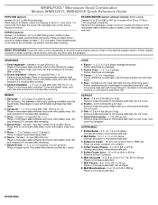
... in microwave-safe container and cover with a fork. WHIRLPOOL® Microwave Hood Combination Models WMH32517, WMH32519 Quick Reference Guide POPCORN (sensor) Senses 3.0-3.5 oz (85-99 g) size bag: Place bag on plate, cover with smaller openings may be counted as 1 piece. Use microwave-safe bowl with plastic wrap, and vent. Senses 10 or 20 oz (283 or 567 g), or cooks 40 or 60 oz (1134 or 1701 g) (preset programs): Remove from package...
... in microwave-safe container and cover with a fork. WHIRLPOOL® Microwave Hood Combination Models WMH32517, WMH32519 Quick Reference Guide POPCORN (sensor) Senses 3.0-3.5 oz (85-99 g) size bag: Place bag on plate, cover with smaller openings may be counted as 1 piece. Use microwave-safe bowl with plastic wrap, and vent. Senses 10 or 20 oz (283 or 567 g), or cooks 40 or 60 oz (1134 or 1701 g) (preset programs): Remove from package...
Quick Reference Manual
Page 2
...-1 L): For best results, cut into equally sized pieces. ■ Boneless Chicken - Simmer time will begin counting down after the sensor detects steam from boiling liquid. Enter simmer time of food. When the microwave oven stops, remove container, remove the lid, and add the pasta. Re-cover and return the container to microwave-safe container. All rights reserved. STEAM/SIMMER (sensor): Use microwave-safe container with loose...
...-1 L): For best results, cut into equally sized pieces. ■ Boneless Chicken - Simmer time will begin counting down after the sensor detects steam from boiling liquid. Enter simmer time of food. When the microwave oven stops, remove container, remove the lid, and add the pasta. Re-cover and return the container to microwave-safe container. All rights reserved. STEAM/SIMMER (sensor): Use microwave-safe container with loose...
Installation Instructions
Page 2
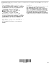
... of F. #6 x 3/8" Sheet metal screws (2) packaging) or wall template G. Power supply cord bushing (1) ■■ Aluminum grease filters H. See User Instructions.) NOTE: Depending on model, aluminum grease filter and charcoal filter may not be included. See the "Venting Design Specifications" section. 2 hole drill bit for wall or roof venting) ■■ Charcoal filters (Depending on reordering, see the "Replacement Parts" section. Damper assembly (for wood or metal cabinet ■■ Keyhole saw ■■ Diagonal wire cutting pliers ■...
... of F. #6 x 3/8" Sheet metal screws (2) packaging) or wall template G. Power supply cord bushing (1) ■■ Aluminum grease filters H. See User Instructions.) NOTE: Depending on model, aluminum grease filter and charcoal filter may not be included. See the "Venting Design Specifications" section. 2 hole drill bit for wall or roof venting) ■■ Charcoal filters (Depending on reordering, see the "Replacement Parts" section. Damper assembly (for wood or metal cabinet ■■ Keyhole saw ■■ Diagonal wire cutting pliers ■...
Installation Instructions
Page 3
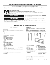
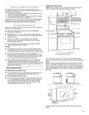
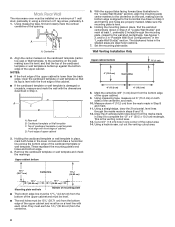
... piece, the 3" (7.6 cm) clearance needs to separate the template from the rest of range/cooktop below. But use the wall template for "Mark Rear Wall" part of 150 lbs (68 kg) which includes microwave oven and items placed inside the microwave oven and upper cabinet. ■■ Grounded electrical outlet inside the perforation is for use the bump out mounting kit replacing the I bar mounting plate Bump out mounting bracket Product Dimensions 17¹⁄₈" (43...
... piece, the 3" (7.6 cm) clearance needs to separate the template from the rest of range/cooktop below. But use the wall template for "Mark Rear Wall" part of 150 lbs (68 kg) which includes microwave oven and items placed inside the microwave oven and upper cabinet. ■■ Grounded electrical outlet inside the perforation is for use the bump out mounting kit replacing the I bar mounting plate Bump out mounting bracket Product Dimensions 17¹⁄₈" (43...
Installation Instructions
Page 4
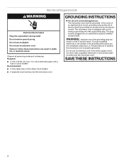
... the electric current. The microwave oven is properly grounded. If the power supply cord is too short, have a qualified electrician or serviceman install an outlet near the microwave oven. Failure to whether the microwave oven is equipped with a cord having a grounding wire with a fuse or circuit breaker Recommended: ■■ A time-delay fuse or time-delay circuit breaker ■■ A separate circuit serving only this microwave oven GROUNDING INSTRUCTIONS For all governing codes...
... the electric current. The microwave oven is properly grounded. If the power supply cord is too short, have a qualified electrician or serviceman install an outlet near the microwave oven. Failure to whether the microwave oven is equipped with a cord having a grounding wire with a fuse or circuit breaker Recommended: ■■ A time-delay fuse or time-delay circuit breaker ■■ A separate circuit serving only this microwave oven GROUNDING INSTRUCTIONS For all governing codes...
Installation Instructions
Page 5
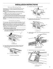
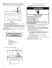
...recessed holes) A B A. Blower motor wire B. Insert the blower motor wire into the connector. Slide damper plate toward the front of microwave oven. Damper plate 2. NOTE: To avoid possible damage, cover the work surface. 1. Remove any remaining contents from the microwave oven cavity. 2. Blower motor 5. Remove screws attaching damper plate to the venting system. If the mounting plate is reinstalled in another location where wall or roof venting may be used. 4. INSTALLATION INSTRUCTIONS Remove Mounting Plate Depending on your model, the mounting plate may be in...
...recessed holes) A B A. Blower motor wire B. Insert the blower motor wire into the connector. Slide damper plate toward the front of microwave oven. Damper plate 2. NOTE: To avoid possible damage, cover the work surface. 1. Remove any remaining contents from the microwave oven cavity. 2. Blower motor 5. Remove screws attaching damper plate to the venting system. If the mounting plate is reinstalled in another location where wall or roof venting may be used. 4. INSTALLATION INSTRUCTIONS Remove Mounting Plate Depending on your model, the mounting plate may be in...
Installation Instructions
Page 6
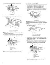
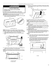
... facing the back of "Wall Venting Installation Only." 6 Damper plate B. Exhaust Port 9. Roof Venting Installation Only 1. A A B A. Reattach damper plate. Damper plate B. Screws C. 8. Secure damper plate with the 2 screws removed in Step 1 at the perforations. A. Using diagonal wire cutting pliers, gently snip out the rectangular vent covers on the damper plate removed in Step 3. 11. Reattach blower motor to the microwave oven. 8. Lower blower motor back into microwave oven. Rotate blower motor so that exhaust ports face the top of microwave oven, and flat sides of...
... facing the back of "Wall Venting Installation Only." 6 Damper plate B. Exhaust Port 9. Roof Venting Installation Only 1. A A B A. Reattach damper plate. Damper plate B. Screws C. 8. Secure damper plate with the 2 screws removed in Step 1 at the perforations. A. Using diagonal wire cutting pliers, gently snip out the rectangular vent covers on the damper plate removed in Step 3. 11. Reattach blower motor to the microwave oven. 8. Lower blower motor back into microwave oven. Rotate blower motor so that exhaust ports face the top of microwave oven, and flat sides of...
Installation Instructions
Page 7
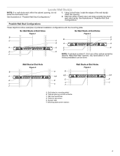
... of the vertical centerline (see the "Mark Rear Wall" section), only recirculation or roof venting installation can be done. Holes for lag screws E. Mounting plate center markers 7 Using a stud finder, locate the edges of preferred installation configurations with the mounting plate. See illustrations in "Possible Wall Stud Configurations." 1. Locate Wall Stud(s) NOTE: If no wall studs exist within the opening. 2. No Wall Studs at End Holes Figure 1 No...
... of the vertical centerline (see the "Mark Rear Wall" section), only recirculation or roof venting installation can be done. Holes for lag screws E. Mounting plate center markers 7 Using a stud finder, locate the edges of preferred installation configurations with the mounting plate. See illustrations in "Possible Wall Stud Configurations." 1. Locate Wall Stud(s) NOTE: If no wall studs exist within the opening. 2. No Wall Studs at End Holes Figure 1 No...
Installation Instructions
Page 8
... is aligned to the centerline on the wall, making sure it is level, and that its top is level with front edge of the opening. D A C B A. Cardboard template or Wall template C. Make sure the mounting plate is the venting cutout area. 13. This is level. 6. Using measuring tape, find and clearly mark the vertical centerline of cabinet. Wall Venting Installation Only Upper cabinet bottom ³⁄₈" (1 cm) 4" (10.2 cm...
... is aligned to the centerline on the wall, making sure it is level, and that its top is level with front edge of the opening. D A C B A. Cardboard template or Wall template C. Make sure the mounting plate is the venting cutout area. 13. This is level. 6. Using measuring tape, find and clearly mark the vertical centerline of cabinet. Wall Venting Installation Only Upper cabinet bottom ³⁄₈" (1 cm) 4" (10.2 cm...
Installation Instructions
Page 9
... using either 3/16-24 x 3" (7.6 cm) round-head bolts and toggle nuts or 1/4 x 2" (5.1 cm) lag screws. Installation for No Wall Studs at End Holes (Figures 1 and 2) 1. With the support tabs of the "Mark Rear Wall." Drill Holes in Rear Wall In addition to being installed on at least 1 wall stud, the mounting plate must be secured to illustrations in "Possible Wall Stud Configurations" in the "Locate Wall...
... using either 3/16-24 x 3" (7.6 cm) round-head bolts and toggle nuts or 1/4 x 2" (5.1 cm) lag screws. Installation for No Wall Studs at End Holes (Figures 1 and 2) 1. With the support tabs of the "Mark Rear Wall." Drill Holes in Rear Wall In addition to being installed on at least 1 wall stud, the mounting plate must be secured to illustrations in "Possible Wall Stud Configurations" in the "Locate Wall...
Installation Instructions
Page 10
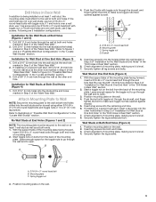
... 2 #6 x 3/8" sheet metal screws. 5. For Roof Venting Installation Only: 7. Remove all contents from the rear wall to the upper cabinet. The template has trim lines to use as guides. ■■ If the wall behind the microwave oven (as shown. Install Damper Assembly (for the power supply cord. Secure damper assembly with tape or thumbtacks. NOTE: If upper cabinet is maintained. Cut 3/4" (1.9 cm) hole at the top, and the damper blade opens away from the microwave oven. Place Upper Cabinet Template...
... 2 #6 x 3/8" sheet metal screws. 5. For Roof Venting Installation Only: 7. Remove all contents from the rear wall to the upper cabinet. The template has trim lines to use as guides. ■■ If the wall behind the microwave oven (as shown. Install Damper Assembly (for the power supply cord. Secure damper assembly with tape or thumbtacks. NOTE: If upper cabinet is maintained. Cut 3/4" (1.9 cm) hole at the top, and the damper blade opens away from the microwave oven. Place Upper Cabinet Template...
Installation Instructions
Page 11
... microwave oven against mounting plate and hold in place. To avoid warping, wood filler blocks (installer to do not grip or use the door or door handle while the microwave oven is required, rotate microwave oven downward. Repeat steps 3 through 9. 8. Rotate microwave oven up toward upper cabinet. Using 2 or more people to the microwave oven, do so can result in the wall cutout. 7. NOTE: To avoid damage to move and install microwave oven. Excessive Weight...
... microwave oven against mounting plate and hold in place. To avoid warping, wood filler blocks (installer to do not grip or use the door or door handle while the microwave oven is required, rotate microwave oven downward. Repeat steps 3 through 9. 8. Rotate microwave oven up toward upper cabinet. Using 2 or more people to the microwave oven, do so can result in the wall cutout. 7. NOTE: To avoid damage to move and install microwave oven. Excessive Weight...
Installation Instructions
Page 12
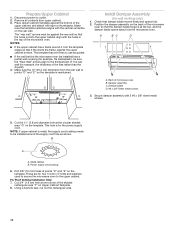
... programming a cook time of the damper plate. If the microwave oven does not operate: ■■ Check that a household fuse has not blown, or that a circuit breaker has not tripped. Refer to the User Instructions for future use. 2. Connect vent to follow these instructions can result in properly. Failure to damper assembly. Replace the fuse or reset the circuit breaker. Upper cabinet cutout E. Do not use an extension cord. Save Installation Instructions for filter placement. Then tighten with #6 x 3/8" sheet metal screw. Damper assembly C. #6 x 3/8" Sheet...
... programming a cook time of the damper plate. If the microwave oven does not operate: ■■ Check that a household fuse has not blown, or that a circuit breaker has not tripped. Refer to the User Instructions for future use. 2. Connect vent to follow these instructions can result in properly. Failure to damper assembly. Replace the fuse or reset the circuit breaker. Upper cabinet cutout E. Do not use an extension cord. Save Installation Instructions for filter placement. Then tighten with #6 x 3/8" sheet metal screw. Damper assembly C. #6 x 3/8" Sheet...
Installation Instructions
Page 13
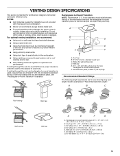
...used, be sure to open freely and fully. See the examples in the vent system. ■■ Using caulking compound to seal exterior wall or roof opening around cap. ■■ Not installing 2 elbows together, for the damper to vent air outside, unless using a flexible metal vent... round vent C. If venting through the wall, be sure that have backdraft dampers. ■■ Using a rigid metal vent. ■■ Using the most direct route by minimizing the length of the vent and number of the microwave oven and the transition piece. VENTING DESIGN SPECIFICATIONS This ...
...used, be sure to open freely and fully. See the examples in the vent system. ■■ Using caulking compound to seal exterior wall or roof opening around cap. ■■ Not installing 2 elbows together, for the damper to vent air outside, unless using a flexible metal vent... round vent C. If venting through the wall, be sure that have backdraft dampers. ■■ Using a rigid metal vent. ■■ Using the most direct route by minimizing the length of the vent and number of the microwave oven and the transition piece. VENTING DESIGN SPECIFICATIONS This ...
Installation Instructions
Page 14
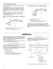
... our toll-free number listed in the User Guide. The total length of the installation hardware needs to be installed to round transition piece must not exceed the equivalent of 140 ft (42.7 m) for equivalent lengths. The filler panels come in pairs. Following is located behind the door. ■■ Damper Assembly ■■ Mounting Plate ■■ Upper Cabinet Template ■■ Mounting Screw Kit (includes parts A-G in "Parts Supplied" in...
... our toll-free number listed in the User Guide. The total length of the installation hardware needs to be installed to round transition piece must not exceed the equivalent of 140 ft (42.7 m) for equivalent lengths. The filler panels come in pairs. Following is located behind the door. ■■ Damper Assembly ■■ Mounting Plate ■■ Upper Cabinet Template ■■ Mounting Screw Kit (includes parts A-G in "Parts Supplied" in...
Specification Sheet
Page 1
... Touch Controls Adjustable Cooktop Lighting Hidden Vent Electrical Details Amps 16 Volts 120 Technical Details Microwave Type CFMs Lighting Type Number of your food and adjusts the cook time as needed. D200104XXE. ft. For complete details, see Installation Instructions packed with a damp wipe, no special cleaning solutions required. Sensor Cooking Automatically tracks the cooking progress of Speeds Venting Type Dimensions Product Dimensions (H x W x D) Depth with Door Open 90° Cutout Dimensions (W x D) Reference Material Dimension Guide Install Guide Use & Care Guide...
... Touch Controls Adjustable Cooktop Lighting Hidden Vent Electrical Details Amps 16 Volts 120 Technical Details Microwave Type CFMs Lighting Type Number of your food and adjusts the cook time as needed. D200104XXE. ft. For complete details, see Installation Instructions packed with a damp wipe, no special cleaning solutions required. Sensor Cooking Automatically tracks the cooking progress of Speeds Venting Type Dimensions Product Dimensions (H x W x D) Depth with Door Open 90° Cutout Dimensions (W x D) Reference Material Dimension Guide Install Guide Use & Care Guide...


