Quick Reference Manual
Page 1
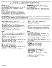
... (283 or 567 g), or cooks 40 or 60 oz (1134 or 1701 g) (preset programs): Remove from package. If entrée is absorbed. Add 2-4 tbs (30-60 mL) water. WHIRLPOOL® Microwave Hood Combination Models WMH32517, WMH32519 Quick Reference Guide POPCORN (sensor) Senses 3.0-3.5 oz (85-99 g) size bag: Place bag on plate, cover with plastic wrap, and vent. Fan operates only on the desired program option. POTATO (sensor) Senses 1-4 potatoes, 10...
... (283 or 567 g), or cooks 40 or 60 oz (1134 or 1701 g) (preset programs): Remove from package. If entrée is absorbed. Add 2-4 tbs (30-60 mL) water. WHIRLPOOL® Microwave Hood Combination Models WMH32517, WMH32519 Quick Reference Guide POPCORN (sensor) Senses 3.0-3.5 oz (85-99 g) size bag: Place bag on plate, cover with plastic wrap, and vent. Fan operates only on the desired program option. POTATO (sensor) Senses 1-4 potatoes, 10...
Quick Reference Manual
Page 2
... begins to the microwave oven. Clear the display using the Cancel control, then reprogram the simmer function, and enter the new simmer time (ex.: dry spaghetti - 11-12 min). Senses 0.5-1.5 lbs (142-680 g) 2 Manual Steam: Place small microwave-safe dish (for more doneness, or when steaming larger quantities. ® /™ © 2013 Whirlpool. When the microwave oven stops, remove container, remove the lid, and...
... begins to the microwave oven. Clear the display using the Cancel control, then reprogram the simmer function, and enter the new simmer time (ex.: dry spaghetti - 11-12 min). Senses 0.5-1.5 lbs (142-680 g) 2 Manual Steam: Place small microwave-safe dish (for more doneness, or when steaming larger quantities. ® /™ © 2013 Whirlpool. When the microwave oven stops, remove container, remove the lid, and...
Installation Instructions
Page 2
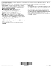
...microwave oven) E. 1/4" x 2" lag screws (2) ■■ Cardboard template (part of F. #6 x 3/8" Sheet metal screws (2) packaging) or wall template G. Washers (2) D. 3/16" toggle nuts (2) ■■ Mounting plate (attached to use appropriate fasteners. hole drill bit for wood studs. Power supply cord bushing (1) ■■ Aluminum grease filters H. Materials Needed Standard fittings for 1/4" x 2" (6.4 mm x 5.1 cm) lag screws ■■ 11/2" (3.8 cm) diam. See User Instructions.) NOTE: Depending on model, charcoal filters may be included. See the "Venting...
...microwave oven) E. 1/4" x 2" lag screws (2) ■■ Cardboard template (part of F. #6 x 3/8" Sheet metal screws (2) packaging) or wall template G. Washers (2) D. 3/16" toggle nuts (2) ■■ Mounting plate (attached to use appropriate fasteners. hole drill bit for wood studs. Power supply cord bushing (1) ■■ Aluminum grease filters H. Materials Needed Standard fittings for 1/4" x 2" (6.4 mm x 5.1 cm) lag screws ■■ 11/2" (3.8 cm) diam. See User Instructions.) NOTE: Depending on model, charcoal filters may be included. See the "Venting...
Installation Instructions
Page 3
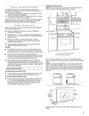
....1 cm), use the wall template for "Mark Rear Wall" part of the cardboard packaging. 2. Remove Cardboard Template The cardboard piece from the top of range/cooktop below. The piece inside the door. ■■ Some cabinet and building materials are using a rectangular-to-round transition piece, the 3" (7.6 cm) clearance needs to withstand the heat produced by the microwave oven for packing. But use the bump out mounting kit replacing the I bar mounting plate Bump out mounting bracket Product Dimensions 17...
....1 cm), use the wall template for "Mark Rear Wall" part of the cardboard packaging. 2. Remove Cardboard Template The cardboard piece from the top of range/cooktop below. The piece inside the door. ■■ Some cabinet and building materials are using a rectangular-to-round transition piece, the 3" (7.6 cm) clearance needs to withstand the heat produced by the microwave oven for packing. But use the bump out mounting kit replacing the I bar mounting plate Bump out mounting bracket Product Dimensions 17...
Installation Instructions
Page 4
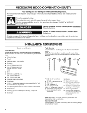
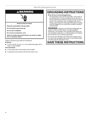
... not use of electric shock by providing an escape wire for the electric current. If the power supply cord is properly grounded. Electrical Requirements WARNING Electrical Shock Hazard Plug into an outlet that is equipped with a cord having a grounding wire with a fuse or circuit breaker Recommended: ■■ A time-delay fuse or time-delay circuit breaker ■■ A separate circuit serving only this microwave oven GROUNDING INSTRUCTIONS For all governing codes...
... not use of electric shock by providing an escape wire for the electric current. If the power supply cord is properly grounded. Electrical Requirements WARNING Electrical Shock Hazard Plug into an outlet that is equipped with a cord having a grounding wire with a fuse or circuit breaker Recommended: ■■ A time-delay fuse or time-delay circuit breaker ■■ A separate circuit serving only this microwave oven GROUNDING INSTRUCTIONS For all governing codes...
Installation Instructions
Page 5
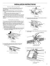
... wire through the blower motor bridge. Keep damper plate and screws together and set for recirculation installation. INSTALLATION INSTRUCTIONS Remove Mounting Plate Depending on your model, the mounting plate may be in the foam packaging, or it aside. 3. If the mounting plate is being handled. Tape the microwave oven door closed so that exhaust ports face the back of the microwave oven, remove it and set it may be made to back of microwave oven exterior. A Wall Venting Installation Only 1. Slide damper plate...
... wire through the blower motor bridge. Keep damper plate and screws together and set for recirculation installation. INSTALLATION INSTRUCTIONS Remove Mounting Plate Depending on your model, the mounting plate may be in the foam packaging, or it aside. 3. If the mounting plate is being handled. Tape the microwave oven door closed so that exhaust ports face the back of the microwave oven, remove it and set it may be made to back of microwave oven exterior. A Wall Venting Installation Only 1. Slide damper plate...
Installation Instructions
Page 6
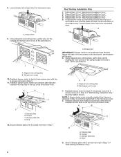
Exhaust Port 9. Repeat Step 2 from "Wall Venting Installation Only." 4. Repeat Step 3 from "Wall Venting Installation Only." 3. Lower blower motor back into the microwave oven. A B C D A. Damper plate tabs D. Using diagonal wire cutting pliers, gently snip out the rectangular vent covers on the damper plate removed in Step 3 of "Wall Venting Installation Only." Rectangular vent covers 7. Screws C. Slots 9. Secure damper plate with 2 screws removed in Step 1. Roof Venting Installation Only 1. Repeat Step 4 from "Wall Venting Installation Only." 2. Secure ...
Exhaust Port 9. Repeat Step 2 from "Wall Venting Installation Only." 4. Repeat Step 3 from "Wall Venting Installation Only." 3. Lower blower motor back into the microwave oven. A B C D A. Damper plate tabs D. Using diagonal wire cutting pliers, gently snip out the rectangular vent covers on the damper plate removed in Step 3 of "Wall Venting Installation Only." Rectangular vent covers 7. Screws C. Slots 9. Secure damper plate with 2 screws removed in Step 1. Roof Venting Installation Only 1. Repeat Step 4 from "Wall Venting Installation Only." 2. Secure ...
Installation Instructions
Page 7
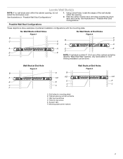
... the opening. 2. Cabinet opening , do not install the microwave oven. Mounting plate center markers 7 Using a stud finder, locate the edges of preferred installation configurations with the mounting plate. Support tabs F. End holes (on mounting plate) B. Mark the center of the vertical centerline (see the "Mark Rear Wall" section), only recirculation or roof venting installation can be done. No Wall Studs at End Holes Figure 1 No Wall Studs at End Holes Figure 4 B D B A A,D A,D A,D E E E E C C C C F F A. Locate Wall Stud...
... the opening. 2. Cabinet opening , do not install the microwave oven. Mounting plate center markers 7 Using a stud finder, locate the edges of preferred installation configurations with the mounting plate. Support tabs F. End holes (on mounting plate) B. Mark the center of the vertical centerline (see the "Mark Rear Wall" section), only recirculation or roof venting installation can be done. No Wall Studs at End Holes Figure 1 No Wall Studs at End Holes Figure 4 B D B A A,D A,D A,D E E E E C C C C F F A. Locate Wall Stud...
Installation Instructions
Page 8
Cardboard template or Wall template C. Front edge of the opening. Remove the cardboard template or wall template and check the markings: Upper cabinet bottom 5. This is level. 6. Using measuring tape, find and clearly mark the vertical centerline of upper cabinet 3. D. Make sure the mounting plate is the venting cutout area. 13. Using measuring tape, measure out 6" (15.2 cm) on both holes in the lower corners and draw a horizontal line across...
Cardboard template or Wall template C. Front edge of the opening. Remove the cardboard template or wall template and check the markings: Upper cabinet bottom 5. This is level. 6. Using measuring tape, find and clearly mark the vertical centerline of upper cabinet 3. D. Make sure the mounting plate is the venting cutout area. 13. Using measuring tape, measure out 6" (15.2 cm) on both holes in the lower corners and draw a horizontal line across...
Installation Instructions
Page 9
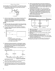
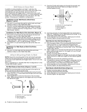
... "Locate all lag screws and bolts. Insert lag screws into both end holes drilled into the remaining end hole. 6. Spring toggle nut D. If installing on the wall. 2. Position mounting plate on the wall. 9 Drill Holes in Rear Wall In addition to being installed on at least 1 wall stud, the mounting plate must be secured to make sure toggle nut has opened against drywall. 5. With the support...
... "Locate all lag screws and bolts. Insert lag screws into both end holes drilled into the remaining end hole. 6. Spring toggle nut D. If installing on the wall. 2. Position mounting plate on the wall. 9 Drill Holes in Rear Wall In addition to being installed on at least 1 wall stud, the mounting plate must be secured to make sure toggle nut has opened against drywall. 5. With the support...
Installation Instructions
Page 10
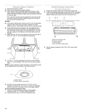
... of t he rear wall (for wall venting only) 1. B A A. Power supply cord bushing 6. Remove all contents from the microwave oven. Make sure the 10" (25.4 cm) dimension from the rear wall to the thickest part of the microwave oven. Damper assembly C. Drill 3/8" (10 mm) holes at one corner of the tiles rather than the drywall). 4. Using a keyhole saw, cut into the upper cabinet align with tape or thumbtacks. A B C D Upper-cabinet template D 10" (25...
... of t he rear wall (for wall venting only) 1. B A A. Power supply cord bushing 6. Remove all contents from the microwave oven. Make sure the 10" (25.4 cm) dimension from the rear wall to the thickest part of the microwave oven. Damper assembly C. Drill 3/8" (10 mm) holes at one corner of the tiles rather than the drywall). 4. Using a keyhole saw, cut into the upper cabinet align with tape or thumbtacks. A B C D Upper-cabinet template D 10" (25...
Installation Instructions
Page 11
... microwave oven. Remove the 2 packing spacers from the top of the upper cabinet. Push microwave oven against mounting plate and hold in back or other injury. To avoid warping, wood filler blocks (installer to be adjusted, skip steps 7 through the wall, make sure the damper assembly fits easily into microwave oven. Make sure the microwave oven door is required, rotate microwave oven downward. Handle the microwave oven gently. 1. A A. NOTE: If microwave oven does not need...
... microwave oven. Remove the 2 packing spacers from the top of the upper cabinet. Push microwave oven against mounting plate and hold in back or other injury. To avoid warping, wood filler blocks (installer to be adjusted, skip steps 7 through the wall, make sure the damper assembly fits easily into microwave oven. Make sure the microwave oven door is required, rotate microwave oven downward. Handle the microwave oven gently. 1. A A. NOTE: If microwave oven does not need...
Installation Instructions
Page 12
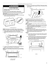
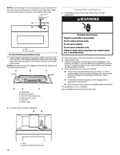
... electrical shock. 2. A B A. WARNING A. Raised tabs B. Do not use an adapter. Reconnect power. 4. Mounting Nut For Roof Venting Installation Only 1. Upper cabinet cutout E. If the microwave oven does not operate: ■■ Check that a household fuse has not blown, or that the power supply cord is plugged into a grounded 3 prong outlet. Save Installation Instructions for filter placement. Vent B. Then secure with tools. Check the operation of 1 minute at 100% power. Test vent fan and exhaust...
... electrical shock. 2. A B A. WARNING A. Raised tabs B. Do not use an adapter. Reconnect power. 4. Mounting Nut For Roof Venting Installation Only 1. Upper cabinet cutout E. If the microwave oven does not operate: ■■ Check that a household fuse has not blown, or that the power supply cord is plugged into a grounded 3 prong outlet. Save Installation Instructions for filter placement. Vent B. Then secure with tools. Check the operation of 1 minute at 100% power. Test vent fan and exhaust...
Installation Instructions
Page 13
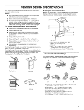
... the rectangular-to -Round Transition" illustration. VENTING DESIGN SPECIFICATIONS This section is used, be sure that have backdraft dampers. ■■ Using a rigid metal vent. ■■ Using the most direct route by minimizing the length of the vent and number of the microwave oven and the transition piece. NOTES: ■■ Vent materials needed for installation are for wall venting only) D. See the examples in the...
... the rectangular-to -Round Transition" illustration. VENTING DESIGN SPECIFICATIONS This section is used, be sure that have backdraft dampers. ■■ Using a rigid metal vent. ■■ Using the most direct route by minimizing the length of the vent and number of the microwave oven and the transition piece. NOTES: ■■ Vent materials needed for installation are for wall venting only) D. See the examples in the...
Installation Instructions
Page 14
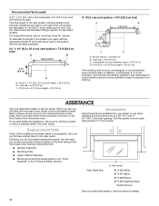
... need the microwave oven model number and serial number. Filler panels 8171336 White 8171337 Black 8171338 Biscuit 8171339 Stainless Steel 99403 Almond See your dealer to -round transition piece = 5 ft (1.5 m) D. 2 ft (0.6 m) + 6 ft (1.8 m) straight = 8 ft (2.4 m) If the existing vent is located behind the door. ■■ Damper Assembly ■■ Mounting Plate ■■ Upper Cabinet Template ■■ Mounting Screw Kit (includes parts A-G in "Parts Supplied" in the "Tools and Parts" section) Filler Panel Kits...
... need the microwave oven model number and serial number. Filler panels 8171336 White 8171337 Black 8171338 Biscuit 8171339 Stainless Steel 99403 Almond See your dealer to -round transition piece = 5 ft (1.5 m) D. 2 ft (0.6 m) + 6 ft (1.8 m) straight = 8 ft (2.4 m) If the existing vent is located behind the door. ■■ Damper Assembly ■■ Mounting Plate ■■ Upper Cabinet Template ■■ Mounting Screw Kit (includes parts A-G in "Parts Supplied" in the "Tools and Parts" section) Filler Panel Kits...
Specification Sheet
Page 1
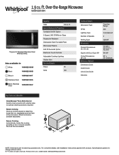
... reserved. WMH32519HSpecSheetV01. General Features & Properties Turntable On/Off Option 3-Speed, 300 CFM Motor Class Fingerprint Resistant Dishwasher-Safe Turntable Plate Microwave Presets Add 30 Seconds Option Electronic Touch Controls Adjustable Cooktop Lighting Hidden Vent Electrical Details Amps 16 Volts 120 Technical Details Microwave Type CFMs Lighting Type Number of your food and adjusts the cook time as needed. NOTE: Dimensions are for planning purposes only. ft. Specifications subject to change without notice. ®...
... reserved. WMH32519HSpecSheetV01. General Features & Properties Turntable On/Off Option 3-Speed, 300 CFM Motor Class Fingerprint Resistant Dishwasher-Safe Turntable Plate Microwave Presets Add 30 Seconds Option Electronic Touch Controls Adjustable Cooktop Lighting Hidden Vent Electrical Details Amps 16 Volts 120 Technical Details Microwave Type CFMs Lighting Type Number of your food and adjusts the cook time as needed. NOTE: Dimensions are for planning purposes only. ft. Specifications subject to change without notice. ®...


