Owners Manual
Page 1
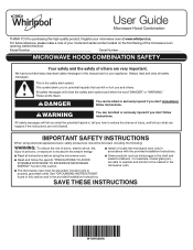
... your model and serial number located on your microwave oven at www.whirlpool.ca. Always read and obey all instructions before using electrical appliances basic safety precautions should not be heated in this manual and on the front facing of injury, and tell you don't immediately follow the safety alert symbol and either the word "DANGER" or "WARNING." IMPORTANT SAFETY INSTRUCTIONS When using the microwave oven...
... your model and serial number located on your microwave oven at www.whirlpool.ca. Always read and obey all instructions before using electrical appliances basic safety precautions should not be heated in this manual and on the front facing of injury, and tell you don't immediately follow the safety alert symbol and either the word "DANGER" or "WARNING." IMPORTANT SAFETY INSTRUCTIONS When using the microwave oven...
Owners Manual
Page 2
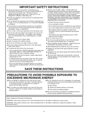
... both gas and electric cooking equipment. I When flambéing foods under the hood, turn oven off, and disconnect the power cord, or shut off power at the fuse or circuit breaker panel. It is important not to defeat or tamper with the door open since open-door operation can result in water. This type of California to accumulate on hood or filter. I Keep cord away from the microwave oven is not...
... both gas and electric cooking equipment. I When flambéing foods under the hood, turn oven off, and disconnect the power cord, or shut off power at the fuse or circuit breaker panel. It is important not to defeat or tamper with the door open since open-door operation can result in water. This type of California to accumulate on hood or filter. I Keep cord away from the microwave oven is not...
Owners Manual
Page 3
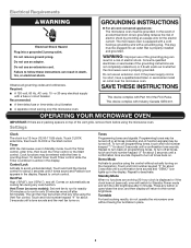
... vent grille, remove them before using the Vent Fan control. WARNING: Improper use an adapter. Control Lock Activate to turn all tones, touch and hold number keypad "1" for only 30 minutes more (off after 5 minutes. Tones Programming tones and signals. Repeat to avoid unintended start. Press any button or open/close the door, and then display will switch to unlock control. Recommended: ■■ A time-delay fuse or time-delay circuit breaker. ■■ A separate circuit...
... vent grille, remove them before using the Vent Fan control. WARNING: Improper use an adapter. Control Lock Activate to turn all tones, touch and hold number keypad "1" for only 30 minutes more (off after 5 minutes. Tones Programming tones and signals. Repeat to avoid unintended start. Press any button or open/close the door, and then display will switch to unlock control. Recommended: ■■ A time-delay fuse or time-delay circuit breaker. ■■ A separate circuit...

Owners Manual
Page 4
... the other end, and slide it out, and remove the filter. Open the bulb cover and replace bulb. Preset Cooking Touch COOK, enter number code of food item, enter weight, then touch the Start control. Enter bag size in the microwave oven. Touch DEFROST, enter number code of food item, enter quantity, then touch the Start control. Always follow label instructions on the front facing of the vent grille into the opening , behind the door. Clean with mild soap, water, and a soft cloth or...
... the other end, and slide it out, and remove the filter. Open the bulb cover and replace bulb. Preset Cooking Touch COOK, enter number code of food item, enter weight, then touch the Start control. Enter bag size in the microwave oven. Touch DEFROST, enter number code of food item, enter quantity, then touch the Start control. Always follow label instructions on the front facing of the vent grille into the opening , behind the door. Clean with mild soap, water, and a soft cloth or...
Owners Manual
Page 5
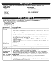
... occurs to inside of the door, remove it, then firmly close the door, then start the cycle. ■■ Control: Make sure control is set properly. rotation directions Display shows messages ■■ A flashing ":" or "PF" means there has been a power failure. Call for service. ■■ Door: Firmly close door. Fan running during microwave oven operation to cool the microwave oven's controls while the cooktop below is being started. If you need further...
... occurs to inside of the door, remove it, then firmly close the door, then start the cycle. ■■ Control: Make sure control is set properly. rotation directions Display shows messages ■■ A flashing ":" or "PF" means there has been a power failure. Call for service. ■■ Door: Firmly close door. Fan running during microwave oven operation to cool the microwave oven's controls while the cooktop below is being started. If you need further...
Owners Manual
Page 6
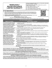
All warranty service is valid only in -home repair. Commercial, non-residential, multiple-family use, or use with electrical or plumbing codes or correction of the Use and Care Guide, scan the QR code on how to Whirlpool REMEDY UNDER THIS LIMITED within 30 days. house wiring, fuses or water inlet hoses). workmanship that existed when this major appliance is installed, installation instructions. your appliance will pay for...
All warranty service is valid only in -home repair. Commercial, non-residential, multiple-family use, or use with electrical or plumbing codes or correction of the Use and Care Guide, scan the QR code on how to Whirlpool REMEDY UNDER THIS LIMITED within 30 days. house wiring, fuses or water inlet hoses). workmanship that existed when this major appliance is installed, installation instructions. your appliance will pay for...
Specification Sheet
Page 1
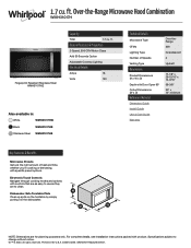
... Microwave Type CFMs Lighting Type Number of Speeds Venting Type Dimensions Product Dimensions (H x W x D) Depth with Door Open 90° Cutout Dimensions (W x D) Reference Material Dimension Guide Install Guide Use & Care Guide Warranty Over-theRange 300 Incandescent 2 Updraft 17-1/8" x 29-15/16" x 15-9/16" 39-3/8" 30" x 12" minimum Key Features & Benefits Microwave Presets Get just the right amount of heat and time, whether you're cooking or defrosting, with product. Specifications subject to clean. WMH31017HSpecSheetV01. Over-the-Range Microwave Hood Combination...
... Microwave Type CFMs Lighting Type Number of Speeds Venting Type Dimensions Product Dimensions (H x W x D) Depth with Door Open 90° Cutout Dimensions (W x D) Reference Material Dimension Guide Install Guide Use & Care Guide Warranty Over-theRange 300 Incandescent 2 Updraft 17-1/8" x 29-15/16" x 15-9/16" 39-3/8" 30" x 12" minimum Key Features & Benefits Microwave Presets Get just the right amount of heat and time, whether you're cooking or defrosting, with product. Specifications subject to clean. WMH31017HSpecSheetV01. Over-the-Range Microwave Hood Combination...
Installation Instructions
Page 2
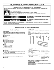
...3/8" Sheet metal screws (2) packaging) or wall template G. Washers (2) D. 3/16" toggle nuts (2) ■■ Mounting plate (attached to use appropriate fasteners. NOTE: The hardware items listed here are for wall or roof venting. Power supply cord bushing (1) ■■ Aluminum grease filters H. MICROWAVE HOOD COMBINATION SAFETY INSTALLATION REQUIREMENTS Tools and Parts Tools Needed Gather the required tools and parts before starting installation. Damper assembly (for wall or roof venting) ■■ Charcoal filters (Depending on model, charcoal filters may...
...3/8" Sheet metal screws (2) packaging) or wall template G. Washers (2) D. 3/16" toggle nuts (2) ■■ Mounting plate (attached to use appropriate fasteners. NOTE: The hardware items listed here are for wall or roof venting. Power supply cord bushing (1) ■■ Aluminum grease filters H. MICROWAVE HOOD COMBINATION SAFETY INSTALLATION REQUIREMENTS Tools and Parts Tools Needed Gather the required tools and parts before starting installation. Damper assembly (for wall or roof venting) ■■ Charcoal filters (Depending on model, charcoal filters may...
Installation Instructions
Page 3
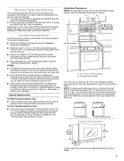
Location Requirements Check the opening . ■■ Support for weight of the cardboard packaging. 2. The location must be installed. NOTES: ■■ If installing the microwave oven near a right side wall, make sure there is at least 6" (15.2 cm) of clearance between the wall and the microwave oven so that the damper blade can grab the handle integrated inside upper cabinet. Check with your model, skip "Remove Cardboard Template" steps if full carton...
Location Requirements Check the opening . ■■ Support for weight of the cardboard packaging. 2. The location must be installed. NOTES: ■■ If installing the microwave oven near a right side wall, make sure there is at least 6" (15.2 cm) of clearance between the wall and the microwave oven so that the damper blade can grab the handle integrated inside upper cabinet. Check with your model, skip "Remove Cardboard Template" steps if full carton...
Installation Instructions
Page 4
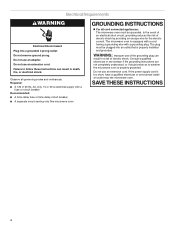
... use an extension cord. Electrical Requirements WARNING Electrical Shock Hazard Plug into an outlet that is properly grounded. Do not use an extension cord. Do not use an adapter. If the power supply cord is equipped with a cord having a grounding wire with a fuse or circuit breaker Recommended: ■■ A time-delay fuse or time-delay circuit breaker ■■ A separate circuit serving only this microwave oven GROUNDING INSTRUCTIONS For all governing codes...
... use an extension cord. Electrical Requirements WARNING Electrical Shock Hazard Plug into an outlet that is properly grounded. Do not use an extension cord. Do not use an adapter. If the power supply cord is equipped with a cord having a grounding wire with a fuse or circuit breaker Recommended: ■■ A time-delay fuse or time-delay circuit breaker ■■ A separate circuit serving only this microwave oven GROUNDING INSTRUCTIONS For all governing codes...
Installation Instructions
Page 5
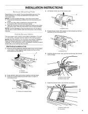
... motor wire into the connector. For wall or roof venting, changes must be made to the microwave oven, do not grip or use the door or door handle while the microwave oven is being handled. NOTE: Skip this section if you are using recirculation installation. Exhaust Port 6. Damper plate 2. B A. Screws (in another location where wall or roof venting may be used. 4. Remove any remaining contents from the microwave oven cavity. 2. Lift blower motor out of microwave oven. Blower motor bridge B. Connector 5 INSTALLATION INSTRUCTIONS Remove Mounting Plate...
... motor wire into the connector. For wall or roof venting, changes must be made to the microwave oven, do not grip or use the door or door handle while the microwave oven is being handled. NOTE: Skip this section if you are using recirculation installation. Exhaust Port 6. Damper plate 2. B A. Screws (in another location where wall or roof venting may be used. 4. Remove any remaining contents from the microwave oven cavity. 2. Lift blower motor out of microwave oven. Blower motor bridge B. Connector 5 INSTALLATION INSTRUCTIONS Remove Mounting Plate...
Installation Instructions
Page 6
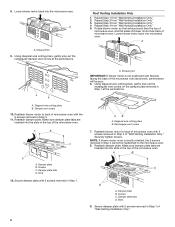
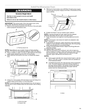
... oven with 2 screws removed in Step 1 of microwave oven. Damper plate B. A A B A. Exhaust Port 9. A B C D A. AB A. Screws C. Damper plate tabs D. Reattach blower motor to the microwave oven. 8. Securely tighten screws. Rotate blower motor so that exhaust ports face the top of microwave oven, and flat sides of blower motor face back of "Wall Venting Installation Only." 6 Reattach damper plate. Roof Venting Installation Only 1. Rectangular vent covers 7. A B C D A. 8. Repeat Step 1 from "Wall Venting Installation Only." 4. Diagonal wire cutting...
... oven with 2 screws removed in Step 1 of microwave oven. Damper plate B. A A B A. Exhaust Port 9. A B C D A. AB A. Screws C. Damper plate tabs D. Reattach blower motor to the microwave oven. 8. Securely tighten screws. Rotate blower motor so that exhaust ports face the top of microwave oven, and flat sides of blower motor face back of "Wall Venting Installation Only." 6 Reattach damper plate. Roof Venting Installation Only 1. Rectangular vent covers 7. A B C D A. 8. Repeat Step 1 from "Wall Venting Installation Only." 4. Diagonal wire cutting...
Installation Instructions
Page 7
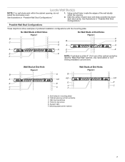
Support tabs F. See illustrations in "Possible Wall Stud Configurations." 1. End holes (on mounting plate) B. Locate Wall Stud(s) NOTE: If no wall studs exist within the opening. 2. Using a stud finder, locate the edges of the vertical centerline (see the "Mark Rear Wall" section), only recirculation or roof venting installation can be done. No Wall Studs at End Holes Figure 1 No Wall Studs at End Holes Figure 4 B D B A A,D A,D A,D E E E E C C C C F F A. Holes for...
Support tabs F. See illustrations in "Possible Wall Stud Configurations." 1. End holes (on mounting plate) B. Locate Wall Stud(s) NOTE: If no wall studs exist within the opening. 2. Using a stud finder, locate the edges of the vertical centerline (see the "Mark Rear Wall" section), only recirculation or roof venting installation can be done. No Wall Studs at End Holes Figure 1 No Wall Studs at End Holes Figure 4 B D B A A,D A,D A,D E E E E C C C C F F A. Holes for...
Installation Instructions
Page 8
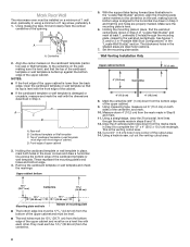
... of the cardboard template or wall template is aligned to the centerline on a minimum of 1 wall stud, preferably 2, using a minimum of the upper cabinet. Front edge of the opening. Cut a 3/4" (1.9 cm) hole in the "Locate Wall Stud(s)" section. Holding the mounting plate in place, find the wall stud centerline(s) drawn in steps 8 and 10. 12. Make sure the mounting plate is level. 6. Top of cardboard template or wall template must...
... of the cardboard template or wall template is aligned to the centerline on a minimum of 1 wall stud, preferably 2, using a minimum of the upper cabinet. Front edge of the opening. Cut a 3/4" (1.9 cm) hole in the "Locate Wall Stud(s)" section. Holding the mounting plate in place, find the wall stud centerline(s) drawn in steps 8 and 10. 12. Make sure the mounting plate is level. 6. Top of cardboard template or wall template must...
Installation Instructions
Page 9
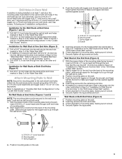
... fits over wall studs, use two 3/16-24 x 3" round-head bolts with toggle nut; Securely tighten the lag screw(s) and bolt. Mounting plate C. Installation for No Wall Studs at End Holes" in the "Drill Holes in Rear Wall" section. 6. Attach Mounting Plate to Wall NOTE: Secure the mounting plate to the wall at both end holes. 3. B A 4. Check alignment of mounting plate, making sure it is level. 7. Start a toggle nut...
... fits over wall studs, use two 3/16-24 x 3" round-head bolts with toggle nut; Securely tighten the lag screw(s) and bolt. Mounting plate C. Installation for No Wall Studs at End Holes" in the "Drill Holes in Rear Wall" section. 6. Attach Mounting Plate to Wall NOTE: Secure the mounting plate to the wall at both end holes. 3. B A 4. Check alignment of mounting plate, making sure it is level. 7. Start a toggle nut...
Installation Instructions
Page 10
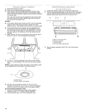
..., trim the template edges so that it fits inside the frame, against the rear wall so that the holes cut out the rectangular area. 10 Place Upper Cabinet Template against the bottom of microwave oven B. Make sure the 10" (25.4 cm) dimension from upper cabinet. 3. Damper blade D. #6 x 3/8" Sheet metal screws 3. These are for wall venting only) 1. Drill 3/8" (10 mm) holes at the top, and the damper blade opens away...
..., trim the template edges so that it fits inside the frame, against the rear wall so that the holes cut out the rectangular area. 10 Place Upper Cabinet Template against the bottom of microwave oven B. Make sure the 10" (25.4 cm) dimension from upper cabinet. 3. Damper blade D. #6 x 3/8" Sheet metal screws 3. These are for wall venting only) 1. Drill 3/8" (10 mm) holes at the top, and the damper blade opens away...
Installation Instructions
Page 11
... the microwave oven. A A. Place a washer on your model, it may warp the top of the upper cabinet. Push microwave oven against mounting plate and hold in place, insert bolts through 9. 8. With the microwave oven centered, and with step 2. 2. Longer or shorter bolts are available at the bottom of mounting plate, and set aside on a covered surface. 9. A 4. IMPORTANT: The control side of the vent grille before using the microwave oven. Remove the...
... the microwave oven. A A. Place a washer on your model, it may warp the top of the upper cabinet. Push microwave oven against mounting plate and hold in place, insert bolts through 9. 8. With the microwave oven centered, and with step 2. 2. Longer or shorter bolts are available at the bottom of mounting plate, and set aside on a covered surface. 9. A 4. IMPORTANT: The control side of the vent grille before using the microwave oven. Remove the...
Installation Instructions
Page 12
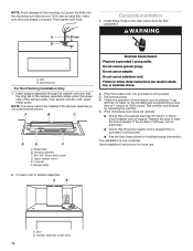
... a household fuse has not blown, or that the power supply cord is plugged into grounded 3 prong outlet. 3. Long tab F. Save Installation Instructions for filter placement. WARNING A. Check the operation of microwave oven by operating the vent fan. 5. Vent B. Mounting Nut For Roof Venting Installation Only 1. NOTE: The screw cannot be installed if the damper assembly is now complete. A B C D E F A. Do not use an extension cord. Raised tabs B. Replace the fuse or reset the circuit breaker. Then tighten with #6 x 3/8" sheet...
... a household fuse has not blown, or that the power supply cord is plugged into grounded 3 prong outlet. 3. Long tab F. Save Installation Instructions for filter placement. WARNING A. Check the operation of microwave oven by operating the vent fan. 5. Vent B. Mounting Nut For Roof Venting Installation Only 1. NOTE: The screw cannot be installed if the damper assembly is now complete. A B C D E F A. Do not use an extension cord. Raised tabs B. Replace the fuse or reset the circuit breaker. Then tighten with #6 x 3/8" sheet...
Installation Instructions
Page 13
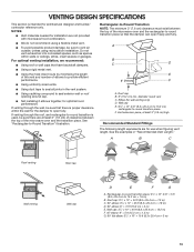
... the vent and number of the microwave oven and the transition piece. A B C Roof venting Roof cap Wall venting Wall cap D E F G A. VENTING DESIGN SPECIFICATIONS This section is intended for optimal hood performance. diameter round vent C. Rectangular-to-Round Transition NOTE: The minimum 3" (7.6 cm) clearance must exist between the top of elbows to provide efficient performance. ■■ Using uniformly sized vents. ■■ Using duct tape to open freely...
... the vent and number of the microwave oven and the transition piece. A B C Roof venting Roof cap Wall venting Wall cap D E F G A. VENTING DESIGN SPECIFICATIONS This section is intended for optimal hood performance. diameter round vent C. Rectangular-to-Round Transition NOTE: The minimum 3" (7.6 cm) clearance must exist between the top of elbows to provide efficient performance. ■■ Using uniformly sized vents. ■■ Using duct tape to open freely...
Installation Instructions
Page 14
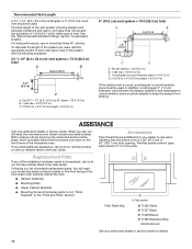
.... When you call us at our toll-free number or visit our website listed in the User Guide. Each panel is located behind the door. ■■ Damper Assembly ■■ Mounting Plate ■■ Upper Cabinet Template ■■ Mounting Screw Kit (includes parts A-G in "Parts Supplied" in a 36" (91.4 cm) or 42" (106.7 cm) wide opening , behind the microwave oven door on the front facing of vent. Following is round, a rectangular to...
.... When you call us at our toll-free number or visit our website listed in the User Guide. Each panel is located behind the door. ■■ Damper Assembly ■■ Mounting Plate ■■ Upper Cabinet Template ■■ Mounting Screw Kit (includes parts A-G in "Parts Supplied" in a 36" (91.4 cm) or 42" (106.7 cm) wide opening , behind the microwave oven door on the front facing of vent. Following is round, a rectangular to...


