Dimension Guide
Page 1
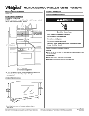
... of 3 Ref. Dimensions are for 66" (167.6 cm) installation height. MICROWAVE HOOD INSTALLATION INSTRUCTIONS PRODUCT MODEL NUMBERS WMH31017H LOCATION REQUIREMENTS Installation Dimensions NOTE: The grounded 3 prong outlet must be inside the upper cabinet. Page 1 of range/ cooktop below. Specifications subject to follow these instructions can result in death, fire, or electrical shock. upper cabinet and side cabinet depth Electrical Shock Hazard Plug into a grounded 3 prong outlet. Observe all governing codes and ordinances.
... of 3 Ref. Dimensions are for 66" (167.6 cm) installation height. MICROWAVE HOOD INSTALLATION INSTRUCTIONS PRODUCT MODEL NUMBERS WMH31017H LOCATION REQUIREMENTS Installation Dimensions NOTE: The grounded 3 prong outlet must be inside the upper cabinet. Page 1 of range/ cooktop below. Specifications subject to follow these instructions can result in death, fire, or electrical shock. upper cabinet and side cabinet depth Electrical Shock Hazard Plug into a grounded 3 prong outlet. Observe all governing codes and ordinances.

Dimension Guide
Page 2
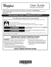
... provide efficient performance ■■ Using uniformly sized vents ■■ Using duct tape to seal all joints in "Recommended Vent Length." For optimal venting installation, we reserve the right to -Round Transition" illustration. A B C D E 3" (7.6 cm) F A. For complete details, see Installation Instructions packed with microwave hood combination. ■■ We do not recommend using recirculation installation. Rectangular-to change materials and specifications without notice. See the examples in...
... provide efficient performance ■■ Using uniformly sized vents ■■ Using duct tape to seal all joints in "Recommended Vent Length." For optimal venting installation, we reserve the right to -Round Transition" illustration. A B C D E 3" (7.6 cm) F A. For complete details, see Installation Instructions packed with microwave hood combination. ■■ We do not recommend using recirculation installation. Rectangular-to change materials and specifications without notice. See the examples in...
Owners Manual
Page 1
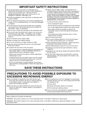
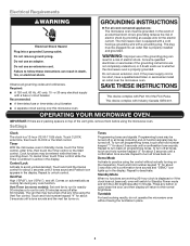
... a note of your microwave oven at www.whirlpool.ca. I Install or locate the microwave oven only in accordance with the provided Installation Instructions. for purchasing this manual and on the front facing of the microwave oven opening, behind the door. I The microwave oven must be grounded. See "GROUNDING INSTRUCTIONS" found in this section and in the provided Installation Instructions. All safety messages will follow the specific "PRECAUTIONS TO AVOID POSSIBLE...
... a note of your microwave oven at www.whirlpool.ca. I Install or locate the microwave oven only in accordance with the provided Installation Instructions. for purchasing this manual and on the front facing of the microwave oven opening, behind the door. I The microwave oven must be grounded. See "GROUNDING INSTRUCTIONS" found in this section and in the provided Installation Instructions. All safety messages will follow the specific "PRECAUTIONS TO AVOID POSSIBLE...
Owners Manual
Page 2
... door surface cleaning instructions in the microwave oven for storage purposes. Remove wire twist-ties from the microwave oven is important not to cause birth defects or other reproductive harm. 2 I When flambéing foods under the hood, turn oven off, and disconnect the power cord, or shut off power at the fuse or circuit breaker panel. I The microwave oven should be used by children. Do not overcook food. I Do not store this oven...
... door surface cleaning instructions in the microwave oven for storage purposes. Remove wire twist-ties from the microwave oven is important not to cause birth defects or other reproductive harm. 2 I When flambéing foods under the hood, turn oven off, and disconnect the power cord, or shut off power at the fuse or circuit breaker panel. I The microwave oven should be used by children. Do not overcook food. I Do not store this oven...
Owners Manual
Page 3
... cooling fan during any cook function. This device complies with a fuse or circuit breaker. Control Lock Activate to unlock control. Vent Fan High ("SPd2"), low ("SPd1"), and off . Demo Mode Activate to practice using the control without having a grounding wire with Part 18 of electric shock by providing an escape wire for only 30 minutes more (off at any button or open/close the door, and then display will switch to Standby Power mode...
... cooling fan during any cook function. This device complies with a fuse or circuit breaker. Control Lock Activate to unlock control. Vent Fan High ("SPd2"), low ("SPd1"), and off . Demo Mode Activate to practice using the control without having a grounding wire with Part 18 of electric shock by providing an escape wire for only 30 minutes more (off at any button or open/close the door, and then display will switch to Standby Power mode...

Owners Manual
Page 4
..., then touch the Start control. Remove 2 screws on the underside of microwave oven. Manual Cooking/Stage Cooking Soften/Melt Touch COOK TIME, touch number keypads to enter time, touch COOK POWER (if not 100%), touch number keypads to soil buildup, keep cavity, microwave inlet cover, cooking rack supports, and area where the door touches the frame clean. The charcoal filter cannot be cleaned and should be replaced about 10 to 13 oz (283 to the right, and secure with screws. 4 Remove bulb cover screws and open the bulb cover. MICROWAVE OVEN CARE General Cleaning IMPORTANT...
..., then touch the Start control. Remove 2 screws on the underside of microwave oven. Manual Cooking/Stage Cooking Soften/Melt Touch COOK TIME, touch number keypads to enter time, touch COOK POWER (if not 100%), touch number keypads to soil buildup, keep cavity, microwave inlet cover, cooking rack supports, and area where the door touches the frame clean. The charcoal filter cannot be cleaned and should be replaced about 10 to 13 oz (283 to the right, and secure with screws. 4 Remove bulb cover screws and open the bulb cover. MICROWAVE OVEN CARE General Cleaning IMPORTANT...
Owners Manual
Page 5
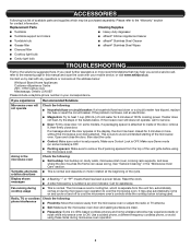
... not operate, call , refer to the warranty page in the microwave oven Check the following: ■■ Soil buildup: Soil buildup on cavity walls, microwave inlet cover, cooking rack supports, and area where the door touches the frame can cause arcing. If water does not heat, try the solutions suggested here. rotation directions Display shows messages ■■ A flashing ":" or "PF" means there has been a power...
... not operate, call , refer to the warranty page in the microwave oven Check the following: ■■ Soil buildup: Soil buildup on cavity walls, microwave inlet cover, cooking rack supports, and area where the door touches the frame can cause arcing. If water does not heat, try the solutions suggested here. rotation directions Display shows messages ■■ A flashing ":" or "PF" means there has been a power...
Owners Manual
Page 6
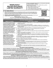
... the limited warranty that existed when this major appliance is installed, installation instructions. In Canada, call 1-800-253-1301. operated and maintained according to use your appliance will pay for service or repair of original purchase date is not available. In-home instruction on how to 2. light bulbs, batteries, air or water filters, preservation solutions, etc.). Defects or damage caused by Whirlpool. workmanship...
... the limited warranty that existed when this major appliance is installed, installation instructions. In Canada, call 1-800-253-1301. operated and maintained according to use your appliance will pay for service or repair of original purchase date is not available. In-home instruction on how to 2. light bulbs, batteries, air or water filters, preservation solutions, etc.). Defects or damage caused by Whirlpool. workmanship...
Specification Sheet
Page 1
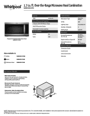
... Number of Speeds Venting Type Dimensions Product Dimensions (H x W x D) Depth with Door Open 90° Cutout Dimensions (W x D) Reference Material Dimension Guide Install Guide Use & Care Guide Warranty Over-theRange 300 Incandescent 2 Updraft 17-1/8" x 29-15/16" x 15-9/16" 39-3/8" 30" x 12" minimum Key Features & Benefits Microwave Presets Get just the right amount of heat and time, whether you're cooking or defrosting, with product. All rights reserved. NOTE: Dimensions are to clean. Dishwasher-Safe Turntable Plate Clean...
... Number of Speeds Venting Type Dimensions Product Dimensions (H x W x D) Depth with Door Open 90° Cutout Dimensions (W x D) Reference Material Dimension Guide Install Guide Use & Care Guide Warranty Over-theRange 300 Incandescent 2 Updraft 17-1/8" x 29-15/16" x 15-9/16" 39-3/8" 30" x 12" minimum Key Features & Benefits Microwave Presets Get just the right amount of heat and time, whether you're cooking or defrosting, with product. All rights reserved. NOTE: Dimensions are to clean. Dishwasher-Safe Turntable Plate Clean...
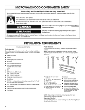
Installation Instructions
Page 2
... bolts (2) ■■ Upper cabinet template C. Power supply cord bushing (1) ■■ Aluminum grease filters H. Washers (2) D. 3/16" toggle nuts (2) ■■ Mounting plate (attached to use appropriate fasteners. See the "Venting Design Specifications" section. 2 See User Instructions.) NOTE: Depending on reordering, see the "Replacement Parts" section. hole drill bit for wood or metal cabinet ■■ Keyhole saw ■■ Diagonal wire cutting pliers ■■ Stud finder...
... bolts (2) ■■ Upper cabinet template C. Power supply cord bushing (1) ■■ Aluminum grease filters H. Washers (2) D. 3/16" toggle nuts (2) ■■ Mounting plate (attached to use appropriate fasteners. See the "Venting Design Specifications" section. 2 See User Instructions.) NOTE: Depending on reordering, see the "Replacement Parts" section. hole drill bit for wood or metal cabinet ■■ Keyhole saw ■■ Diagonal wire cutting pliers ■■ Stud finder...
Installation Instructions
Page 3
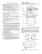
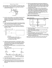
... installing the microwave oven near a right side wall, make sure that the door can open fully. ■■ Some models have a pocket handle. upper cabinet and side cabinet depth A. 2" x 4" (5.1 x 10.2 cm) wall stud B. The location must be inside the perforation is at least 3 inches of clearance between the wall and the microwave oven so that the materials used for use the bump out mounting kit replacing the I bar mounting plate Bump out mounting bracket Product Dimensions...
... installing the microwave oven near a right side wall, make sure that the door can open fully. ■■ Some models have a pocket handle. upper cabinet and side cabinet depth A. 2" x 4" (5.1 x 10.2 cm) wall stud B. The location must be inside the perforation is at least 3 inches of clearance between the wall and the microwave oven so that the materials used for use the bump out mounting kit replacing the I bar mounting plate Bump out mounting bracket Product Dimensions...
Installation Instructions
Page 4
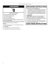
... the electric current. The plug must be plugged into a grounded 3 prong outlet. If the power supply cord is equipped with a cord having a grounding wire with a fuse or circuit breaker Recommended: ■■ A time-delay fuse or time-delay circuit breaker ■■ A separate circuit serving only this microwave oven GROUNDING INSTRUCTIONS For all governing codes and ordinances. Do not remove ground prong. Observe all cord connected appliances: The microwave oven...
... the electric current. The plug must be plugged into a grounded 3 prong outlet. If the power supply cord is equipped with a cord having a grounding wire with a fuse or circuit breaker Recommended: ■■ A time-delay fuse or time-delay circuit breaker ■■ A separate circuit serving only this microwave oven GROUNDING INSTRUCTIONS For all governing codes and ordinances. Do not remove ground prong. Observe all cord connected appliances: The microwave oven...
Installation Instructions
Page 5
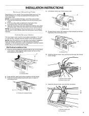
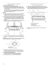
..., cover the work surface. 1. NOTE: Skip this section if you are using recirculation installation. Slide damper plate toward the front of microwave oven. A A. B A. Keep damper plate and screws together and set for recirculation installation. A B A. INSTALLATION INSTRUCTIONS Remove Mounting Plate Depending on your model, the mounting plate may be in another location where wall or roof venting may be made to the venting system. NOTE: To avoid damage to the microwave oven, do not grip or use the door or door handle...
..., cover the work surface. 1. NOTE: Skip this section if you are using recirculation installation. Slide damper plate toward the front of microwave oven. A A. B A. Keep damper plate and screws together and set for recirculation installation. A B A. INSTALLATION INSTRUCTIONS Remove Mounting Plate Depending on your model, the mounting plate may be in another location where wall or roof venting may be made to the venting system. NOTE: To avoid damage to the microwave oven, do not grip or use the door or door handle...
Installation Instructions
Page 6
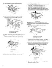
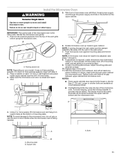
... "Wall Venting Installation Only." A A B A. Diagonal wire cutting pliers B. Damper vent covers 10. Slots 12. Exhaust port IMPORTANT: If blower motor is not correctly oriented, the 2 screws removed in Step 3 cannot be poor. 6. A A. Lower blower motor back into the microwave oven. Reattach blower motor to back of microwave oven with 2 screws removed in the top of "Wall Venting Installation Only." 6 Make sure damper plate tabs are inserted into the slots in Step 1 of the microwave oven. A B C D A. Damper plate tabs D. Using diagonal wire cutting...
... "Wall Venting Installation Only." A A B A. Diagonal wire cutting pliers B. Damper vent covers 10. Slots 12. Exhaust port IMPORTANT: If blower motor is not correctly oriented, the 2 screws removed in Step 3 cannot be poor. 6. A A. Lower blower motor back into the microwave oven. Reattach blower motor to back of microwave oven with 2 screws removed in the top of "Wall Venting Installation Only." 6 Make sure damper plate tabs are inserted into the slots in Step 1 of the microwave oven. A B C D A. Damper plate tabs D. Using diagonal wire cutting...
Installation Instructions
Page 7
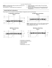
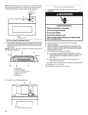
... exist within the opening. 2. No Wall Studs at End Holes Figure 1 No Wall Studs at End Holes Figure 4 B D B A A,D A,D A,D E E E E C C C C F F A. Cabinet opening , do not install the microwave oven. Support tabs F. See illustrations in "Possible Wall Stud Configurations." 1. End holes (on mounting plate) B. Mounting plate center markers 7 Using a stud finder, locate the edges of the vertical centerline (see the "Mark Rear Wall" section), only recirculation or roof venting installation can be done. See...
... exist within the opening. 2. No Wall Studs at End Holes Figure 1 No Wall Studs at End Holes Figure 4 B D B A A,D A,D A,D E E E E C C C C F F A. Cabinet opening , do not install the microwave oven. Support tabs F. See illustrations in "Possible Wall Stud Configurations." 1. End holes (on mounting plate) B. Mounting plate center markers 7 Using a stud finder, locate the edges of the vertical centerline (see the "Mark Rear Wall" section), only recirculation or roof venting installation can be done. See...
Installation Instructions
Page 8
... edge of the cutout area. 14. Cardboard template or Wall template C. These represent the mounting plate's end holes and bottom edge. 4. Cut a 3/4" (1.9 cm) hole in one corner of upper cabinet 3. Using measuring tape, find and clearly mark the vertical centerline of the upper cabinet. 9. With the support tabs facing forward (see illustrations in the "Locate Wall Stud(s)" section), align the mounting plate center markers to the...
... edge of the cutout area. 14. Cardboard template or Wall template C. These represent the mounting plate's end holes and bottom edge. 4. Cut a 3/4" (1.9 cm) hole in one corner of upper cabinet 3. Using measuring tape, find and clearly mark the vertical centerline of the upper cabinet. 9. With the support tabs facing forward (see illustrations in the "Locate Wall Stud(s)" section), align the mounting plate center markers to the...
Installation Instructions
Page 10
... rear wall. Using a keyhole saw, cut into the upper cabinet align with 2 #6 x 3/8" sheet metal screws. 5. The template has trim lines to use as guides. ■■ If the wall behind the microwave oven (as shown. NOTES: ■■ If the upper cabinet has a frame around the supply cord hole as installed) has a partial wall covering (for wall venting only) 1. Secure damper assembly with the holes in the top of microwave oven B. Metal cabinet B. For Roof Venting Installation Only: 7. Remove...
... rear wall. Using a keyhole saw, cut into the upper cabinet align with 2 #6 x 3/8" sheet metal screws. 5. The template has trim lines to use as guides. ■■ If the wall behind the microwave oven (as shown. NOTES: ■■ If the upper cabinet has a frame around the supply cord hole as installed) has a partial wall covering (for wall venting only) 1. Secure damper assembly with the holes in the top of microwave oven B. Metal cabinet B. For Roof Venting Installation Only: 7. Remove...
Installation Instructions
Page 11
... cabinet and microwave oven. Support tabs A. Install the Microwave Oven WARNING 5. Excessive Weight Hazard Use two or more people to do not grip or use the door or door handle while the microwave oven is the heavy side. Remove the 2 packing spacers from the top of mounting plate, and set aside on your model, it on each 1/4-20 x 3" flat-head bolt and place inside upper cabinet near the 3/8" (10 mm) holes. 3. Rotate microwave oven...
... cabinet and microwave oven. Support tabs A. Install the Microwave Oven WARNING 5. Excessive Weight Hazard Use two or more people to do not grip or use the door or door handle while the microwave oven is the heavy side. Remove the 2 packing spacers from the top of mounting plate, and set aside on your model, it on each 1/4-20 x 3" flat-head bolt and place inside upper cabinet near the 3/8" (10 mm) holes. 3. Rotate microwave oven...
Installation Instructions
Page 12
... power. 4. Replace the fuse or reset the circuit breaker. Save Installation Instructions for filter placement. Damper assembly (under the raised tabs of 1 minute at 100% power. Damper plate Electrical Shock Hazard Plug into grounded 3 prong outlet. 3. Then tighten with #6 x 3/8" sheet metal screw. A 15-20 mm B Complete Installation 1. Refer to the User Instructions for future use. 2. If the microwave oven does not operate: ■■ Check that a household fuse has not blown, or that the power supply cord...
... power. 4. Replace the fuse or reset the circuit breaker. Save Installation Instructions for filter placement. Damper assembly (under the raised tabs of 1 minute at 100% power. Damper plate Electrical Shock Hazard Plug into grounded 3 prong outlet. 3. Then tighten with #6 x 3/8" sheet metal screw. A 15-20 mm B Complete Installation 1. Refer to the User Instructions for future use. 2. If the microwave oven does not operate: ■■ Check that a household fuse has not blown, or that the power supply cord...
Installation Instructions
Page 14
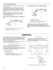
For best performance, use when installing this microwave oven in a 36" (91.4 cm) or 42" (106.7 cm) wide opening , behind the microwave oven door on the model and serial number plate, which is a list of each vent piece used . To calculate the length of the system you will need , add the equivalent lengths of available replacement parts. Two 90° elbows = 20 ft (6.1 m) B. 1 wall cap = 40 ft (12.2 m) C. 1 rectangular-to...
For best performance, use when installing this microwave oven in a 36" (91.4 cm) or 42" (106.7 cm) wide opening , behind the microwave oven door on the model and serial number plate, which is a list of each vent piece used . To calculate the length of the system you will need , add the equivalent lengths of available replacement parts. Two 90° elbows = 20 ft (6.1 m) B. 1 wall cap = 40 ft (12.2 m) C. 1 rectangular-to...


