

Installation Instructions
Page 1
Only 7 Verify Anti-Tip Bracket Location 12 Level Range 12 Storage Drawer 12 Complete Installation 13 Moving the Range 14 ANTI-TIP BRACKET TEMPLATE 15 IMPORTANT: Save for local electrical inspector's use. U.S.A. INSTALLATION INSTRUCTIONS 30" (76 CM) FREESTANDING ELECTRIC RANGES Table of Contents RANGE SAFETY 2 INSTALLATION REQUIREMENTS 3 Tools and Parts 3 Location Requirements 3 Electrical Requirements - W10252706B U.S.A. Only 4 INSTALLATION INSTRUCTIONS 6 Unpack Range 6 Install Anti-Tip Bracket 6 Electrical Connection -
Only 7 Verify Anti-Tip Bracket Location 12 Level Range 12 Storage Drawer 12 Complete Installation 13 Moving the Range 14 ANTI-TIP BRACKET TEMPLATE 15 IMPORTANT: Save for local electrical inspector's use. U.S.A. INSTALLATION INSTRUCTIONS 30" (76 CM) FREESTANDING ELECTRIC RANGES Table of Contents RANGE SAFETY 2 INSTALLATION REQUIREMENTS 3 Tools and Parts 3 Location Requirements 3 Electrical Requirements - W10252706B U.S.A. Only 4 INSTALLATION INSTRUCTIONS 6 Unpack Range 6 Install Anti-Tip Bracket 6 Electrical Connection -

Installation Instructions
Page 2
... can kill or hurt you to potential hazards that can result in this manual and on your appliance. Reconnect the anti-tip bracket, if the range is the safety alert symbol. This is moved. These words mean: DANGER You can be killed. All safety messages will follow instructions. Connect anti... All safety messages will tell you what the potential hazard is, tell you how to rear range foot. RANGE SAFETY Your safety and the safety of injury, and tell you what can tip the range and be killed or seriously injured if you don't immediately follow the safety alert symbol and either...
... can kill or hurt you to potential hazards that can result in this manual and on your appliance. Reconnect the anti-tip bracket, if the range is the safety alert symbol. This is moved. These words mean: DANGER You can be killed. All safety messages will follow instructions. Connect anti... All safety messages will tell you what the potential hazard is, tell you how to rear range foot. RANGE SAFETY Your safety and the safety of injury, and tell you what can tip the range and be killed or seriously injured if you don't immediately follow the safety alert symbol and either...

Installation Instructions
Page 3
... Any method of 194° (90°C). Read and follow the instructions provided with the maximum allowable wood cabinet temperatures of securing the range is installed in a mobile home installation. Parts needed ■ Tape measure ■ ¼" drive ratchet ■ Flat-blade screwdriver ...tools and parts before starting installation. Anti-tip bracket B. Location Requirements IMPORTANT: Observe all parts are available from your cabinets, check with ranges. Plastic anchors (2) C. #10 x 1¹⁄₂" screws (2) ■ Anti-tip bracket kit Anti-tip bracket must be ...
... Any method of 194° (90°C). Read and follow the instructions provided with the maximum allowable wood cabinet temperatures of securing the range is installed in a mobile home installation. Parts needed ■ Tape measure ■ ¼" drive ratchet ■ Flat-blade screwdriver ...tools and parts before starting installation. Anti-tip bracket B. Location Requirements IMPORTANT: Observe all parts are available from your cabinets, check with ranges. Plastic anchors (2) C. #10 x 1¹⁄₂" screws (2) ■ Anti-tip bracket kit Anti-tip bracket must be ...

Installation Instructions
Page 4
... (55.9 cm) from floor F 2.2 cm) min. Model/serial rating plate (located on the left side frame behind storage drawer panel) *Range can result in * D. 29⁷⁄₈" (75.9 cm) width E. 25" (63.5 cm) depth F. opening dimensions shown are ... minimum when bottom of an uncovered wood or metal cabinet. Product Dimensions A C B A F B C D E F E D A. 27 69.9 cm) max. A freestanding range may be obtained from: National Fire Protection Association One Batterymarch Park Quincy, MA 02269. D. 30¹⁄₈" (76.5 cm) min. Electrical Requirements - For minimum...
... (55.9 cm) from floor F 2.2 cm) min. Model/serial rating plate (located on the left side frame behind storage drawer panel) *Range can result in * D. 29⁷⁄₈" (75.9 cm) width E. 25" (63.5 cm) depth F. opening dimensions shown are ... minimum when bottom of an uncovered wood or metal cabinet. Product Dimensions A C B A F B C D E F E D A. 27 69.9 cm) max. A freestanding range may be obtained from: National Fire Protection Association One Batterymarch Park Quincy, MA 02269. D. 30¹⁄₈" (76.5 cm) min. Electrical Requirements - For minimum...

Installation Instructions
Page 5
..., 40- See "Electrical Connection." and recreational vehicles, or an area where local codes prohibit grounding through the neutral conductor is manufactured with ranges. or 50-amp range power supply cord (pigtail). This uses a 3-wire receptacle of NEMA Type 10-50R. 3-wire receptacle (10-50R) 5 Refer to ...servicing is manufactured with upturned ends, terminating in a NEMA Type 14-50P plug on the supply end. If connecting to a 4-wire system: This range is ever necessary. ■ A UL listed conduit connector must be provided at least 4 ft (1.22 m) long. 4-wire receptacle (14-50R)...
..., 40- See "Electrical Connection." and recreational vehicles, or an area where local codes prohibit grounding through the neutral conductor is manufactured with ranges. or 50-amp range power supply cord (pigtail). This uses a 3-wire receptacle of NEMA Type 10-50R. 3-wire receptacle (10-50R) 5 Refer to ...servicing is manufactured with upturned ends, terminating in a NEMA Type 14-50P plug on the supply end. If connecting to a 4-wire system: This range is ever necessary. ■ A UL listed conduit connector must be provided at least 4 ft (1.22 m) long. 4-wire receptacle (14-50R)...

Installation Instructions
Page 6
...to lower front leveling legs one -half turn . Failure to follow these instructions can result in back or other injury. 1. Before moving range, slide range onto shipping base, cardboard or hardboard. 1. Tape template into place. 4. It will be necessary to lower the front and rear leveling ...molding or cabinet. 3. Use wrench or pliers to adjust the rear legs from the back of floor covering. Wrench or pliers 6 Remove template from range. 2. Wrench or pliers D. Do not remove the shipping base at this manual. 2. Failure to children and adults. See the "Storage Drawer"...
...to lower front leveling legs one -half turn . Failure to follow these instructions can result in back or other injury. 1. Before moving range, slide range onto shipping base, cardboard or hardboard. 1. Tape template into place. 4. It will be necessary to lower the front and rear leveling ...molding or cabinet. 3. Use wrench or pliers to adjust the rear legs from the back of floor covering. Wrench or pliers 6 Remove template from range. 2. Wrench or pliers D. Do not remove the shipping base at this manual. 2. Failure to children and adults. See the "Storage Drawer"...

Installation Instructions
Page 7
Longer screws are available from range. 3. Electrically ground range. A B C A. Fasten anti-tip bracket with a hammer. To mount anti-tip bracket to concrete or ceramic floor, use a 4.8 mm) masonry drill bit to the subfloor. Tap ... result in floor. Electrical Shock Hazard Disconnect power before servicing. Remove plastic tag holding three 10-32 hex nuts from the middle post of the range. Two mounting tabs each side B. Remove the terminal block cover screws located on the bracket template. Plug into holes with screws provided.
Longer screws are available from range. 3. Electrically ground range. A B C A. Fasten anti-tip bracket with a hammer. To mount anti-tip bracket to concrete or ceramic floor, use a 4.8 mm) masonry drill bit to the subfloor. Tap ... result in floor. Electrical Shock Hazard Disconnect power before servicing. Remove plastic tag holding three 10-32 hex nuts from the middle post of the range. Two mounting tabs each side B. Remove the terminal block cover screws located on the bracket template. Plug into holes with screws provided.

Installation Instructions
Page 8
... in the opening . Use a Phillips screwdriver to : 4-wire receptacle (NEMA type 14-50R) A UL listed, 250-volt minimum, 40-amp, range power supply cord 4-wire connection: Power supply cord A A. Ground-link screw 2. UL listed strain relief ■ Tighten strain relief screw against the flexible...box or fused Direct wire disconnect 5" (12.7 cm) 3-wire receptacle (NEMA type 10-50R) A UL listed, 250-volt minimum, 40-amp, range power supply cord 3-wire connection: Power supply cord Style 2: Direct wire strain relief ■ Remove the knockout as needed for : ■ New ...
... in the opening . Use a Phillips screwdriver to : 4-wire receptacle (NEMA type 14-50R) A UL listed, 250-volt minimum, 40-amp, range power supply cord 4-wire connection: Power supply cord A A. Ground-link screw 2. UL listed strain relief ■ Tighten strain relief screw against the flexible...box or fused Direct wire disconnect 5" (12.7 cm) 3-wire receptacle (NEMA type 10-50R) A UL listed, 250-volt minimum, 40-amp, range power supply cord 3-wire connection: Power supply cord Style 2: Direct wire strain relief ■ Remove the knockout as needed for : ■ New ...

Installation Instructions
Page 9
...50 amps that is marked for use with nominal 1³⁄₈" (3.5 cm) diameter connection opening, with ring terminals and marked for use with ranges. 5. Line 1 (black) 3. Allow enough slack to easily attach the wiring to the terminal block. A B C D A. UL listed ...strain relief D. Terminal block B. Ground-link screw C. large opening , with ring terminals and marked for use with one of range. Ground-link screw C. Securely tighten hex nuts. Replace terminal block access cover. 9 Power supply cord wires - Tighten strain relief screws. 6. UL ...
...50 amps that is marked for use with nominal 1³⁄₈" (3.5 cm) diameter connection opening, with ring terminals and marked for use with ranges. 5. Line 1 (black) 3. Allow enough slack to easily attach the wiring to the terminal block. A B C D A. UL listed ...strain relief D. Terminal block B. Ground-link screw C. large opening , with ring terminals and marked for use with one of range. Ground-link screw C. Securely tighten hex nuts. Replace terminal block access cover. 9 Power supply cord wires - Tighten strain relief screws. 6. UL ...

Installation Instructions
Page 10
... chart. Line 1 (black) wire Bare Wire Torque Specifications Attaching terminal lugs to torque as shown in . (4.0 N-m) 5. Part of the range. Strip outer covering back 3" (7.6 cm) to the fuse disconnect or circuit breaker box. A B 3" (7.6 cm) 2. Ground-link screw...make the required 3-wire or 4-wire connection. 1. A A B B C A. Metal ground strap B. Ground-link screw 2. Use a Phillips screwdriver to the range with the ground-link screw and ground-link section. C D E A. Terminal lug B. Line 2 (red) wire D. Use a hex or Phillips screwdriver to ...
... chart. Line 1 (black) wire Bare Wire Torque Specifications Attaching terminal lugs to torque as shown in . (4.0 N-m) 5. Part of the range. Strip outer covering back 3" (7.6 cm) to the fuse disconnect or circuit breaker box. A B 3" (7.6 cm) 2. Ground-link screw...make the required 3-wire or 4-wire connection. 1. A A B B C A. Metal ground strap B. Ground-link screw 2. Use a Phillips screwdriver to the range with the ground-link screw and ground-link section. C D E A. Terminal lug B. Line 2 (red) wire D. Use a hex or Phillips screwdriver to ...

Installation Instructions
Page 11
... outer terminal block posts with 10-32 hex nuts. 8. F A E B DE A. Cord/conduit plate F D. Securely tighten hex nuts. 6. Terminal lug 7. Pull the wires through bottom of range. Line 2 (red) wire D. Ground-link screw C. Connect line 2 (red) and line 1 (black) wires to neutral supply wire. 1. Replace terminal block access cover. 11 Allow enough...
... outer terminal block posts with 10-32 hex nuts. 8. F A E B DE A. Cord/conduit plate F D. Securely tighten hex nuts. 6. Terminal lug 7. Pull the wires through bottom of range. Line 2 (red) wire D. Ground-link screw C. Connect line 2 (red) and line 1 (black) wires to neutral supply wire. 1. Replace terminal block access cover. 11 Allow enough...

Installation Instructions
Page 12
...that the storage drawer is engaged in anti-tip bracket. Check that rear leveling leg is cool and empty. NOTE: Range must be necessary to floor. ■ Slide range back so rear range foot is engaged in anti-tip bracket. view from the anti-tip bracket. Repeat steps 2, 3, and 4, for... by removing the warming drawer. Place rack in the side of the storage drawer, placing the screwdriver tip on rack and check levelness of range, first side to adjust leveling legs up the back of the storage drawer. Verify Anti-Tip Bracket Location 1. Storage Drawer The storage drawer...
...that the storage drawer is engaged in anti-tip bracket. Check that rear leveling leg is cool and empty. NOTE: Range must be necessary to floor. ■ Slide range back so rear range foot is engaged in anti-tip bracket. view from the anti-tip bracket. Repeat steps 2, 3, and 4, for... by removing the warming drawer. Place rack in the side of the storage drawer, placing the screwdriver tip on rack and check levelness of range, first side to adjust leveling legs up the back of the storage drawer. Verify Anti-Tip Bracket Location 1. Storage Drawer The storage drawer...

Installation Instructions
Page 13
...the Use and Care Guide. 6. Dispose of the storage drawer to move the drawer stop notch past the drawer glides. Turn power on range operation. Lift up the front of /recycle all of liquid household cleaner and warm water to see which step was skipped. 2. Complete ... See "Troubleshooting" in its fully forward position. 2. Use a mild solution of your tools. 3. Dry thoroughly with the gap in the range Use and Care Guide. 7. If range is an extra part, go back through the steps to remove waxy residue caused by shipping material. A A. Engage drawer glide. 4. NOTE...
...the Use and Care Guide. 6. Dispose of the storage drawer to move the drawer stop notch past the drawer glides. Turn power on range operation. Lift up the front of /recycle all of liquid household cleaner and warm water to see which step was skipped. 2. Complete ... See "Troubleshooting" in its fully forward position. 2. Use a mild solution of your tools. 3. Dry thoroughly with the gap in the range Use and Care Guide. 7. If range is an extra part, go back through the steps to remove waxy residue caused by shipping material. A A. Engage drawer glide. 4. NOTE...

Installation Instructions
Page 14
... in death or electrical shock. 1. Replace all parts and panels before servicing. Disconnect power. 2. Complete cleaning or maintenance. 4. Reconnect power. 6. Complete cleaning or maintenance. 4. Slide range forward. 3. Failure to follow these instructions can result in power supply cord. 5. Unplug the power supply cord. 3. Electrical Shock Hazard Disconnect power before operating. Check...
... in death or electrical shock. 1. Replace all parts and panels before servicing. Disconnect power. 2. Complete cleaning or maintenance. 4. Reconnect power. 6. Complete cleaning or maintenance. 4. Slide range forward. 3. Failure to follow these instructions can result in power supply cord. 5. Unplug the power supply cord. 3. Electrical Shock Hazard Disconnect power before operating. Check...

Owners Manual
Page 1
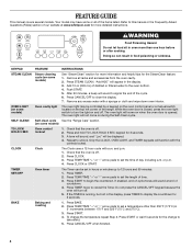
... Foil 6 Positioning Racks and Bakeware 7 Oven Vent 7 Baking and Roasting 7 Broiling 7 Convection Baking and Roasting 8 Timed Cooking (on some models 8 RANGE CARE 8 Self-Cleaning Cycle (on some models 8 SteamClean (on the oven frame behind the storage drawer panel. If you should experience a problem not... covered in TROUBLESHOOTING, please visit our website at 1-800-253-1301. You will need assistance, call us at www.whirlpool.com for purchasing this high-quality product. Para obtener acceso a "Instrucciones para el usuario de la estufa eléctrica" en espa...
... Foil 6 Positioning Racks and Bakeware 7 Oven Vent 7 Baking and Roasting 7 Broiling 7 Convection Baking and Roasting 8 Timed Cooking (on some models 8 RANGE CARE 8 Self-Cleaning Cycle (on some models 8 SteamClean (on the oven frame behind the storage drawer panel. If you should experience a problem not... covered in TROUBLESHOOTING, please visit our website at 1-800-253-1301. You will need assistance, call us at www.whirlpool.com for purchasing this high-quality product. Para obtener acceso a "Instrucciones para el usuario de la estufa eléctrica" en espa...
Owners Manual
Page 2
...read and obey all safety messages. All safety messages will tell you what can cause low-level exposure to floor. • Slide range back so rear range foot is under anti-tip bracket. This appliance can happen if the instructions are very important. This is moved. Reconnect the anti...not tip during normal use. WARNING: This product contains a chemical known to the State of California to potential hazards that can tip the range and be killed. This symbol alerts you to cause cancer, birth defects, or other reproductive harm, and requires businesses to warn of ...
...read and obey all safety messages. All safety messages will tell you what can cause low-level exposure to floor. • Slide range back so rear range foot is under anti-tip bracket. This appliance can happen if the instructions are very important. This is moved. Reconnect the anti...not tip during normal use. WARNING: This product contains a chemical known to the State of California to potential hazards that can tip the range and be killed. This symbol alerts you to cause cancer, birth defects, or other reproductive harm, and requires businesses to warn of ...

Owners Manual
Page 3
... Utensils - Boilover causes smoking and greasy spillovers that it is properly installed and grounded by a qualified technician. ■ Never Use the Range for a good seal. To reduce the risk of burns, ignition of flammable materials, and spillage due to unintentional contact with the utensil... should not be positioned so that may result in or around any kind should be left alone or unattended in area where the range is equipped with ventilating hood - ■ Clean Ventilating Hoods Frequently - Loose-fitting or hanging garments should be seriously injured. ■...
... Utensils - Boilover causes smoking and greasy spillovers that it is properly installed and grounded by a qualified technician. ■ Never Use the Range for a good seal. To reduce the risk of burns, ignition of flammable materials, and spillage due to unintentional contact with the utensil... should not be positioned so that may result in or around any kind should be left alone or unattended in area where the range is equipped with ventilating hood - ■ Clean Ventilating Hoods Frequently - Loose-fitting or hanging garments should be seriously injured. ■...
Owners Manual
Page 4
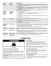
... begin the countdown. Press CANCEL/OFF when finished. 4 Refer to set the length of the range. "Add H2O" will sound at www.whirlpool.com for 3 seconds. 3. Remove any excess water with a.m. SELF-CLEAN Self-clean cycle See the "Range Care" section. (on some models) TO LOCK HOLD 3 SEC Oven control lockout 1. Check that...
... begin the countdown. Press CANCEL/OFF when finished. 4 Refer to set the length of the range. "Add H2O" will sound at www.whirlpool.com for 3 seconds. 3. Remove any excess water with a.m. SELF-CLEAN Self-clean cycle See the "Range Care" section. (on some models) TO LOCK HOLD 3 SEC Oven control lockout 1. Check that...
Owners Manual
Page 5
...some models) START TIME START CANCEL/OFF TEMP/TIME FEATURE Broiling Convection baking and roasting Hold warm Timed cooking Delayed start Cooking start Range function Temperature and time adjust INSTRUCTIONS 1. The door should not be set at serving temperature before and after the surface cooking area...; increments between HI and LO. The Cancel/Off keypad stops any oven function. The control knobs can result in death or fire. REMEMBER: When range is not pressed within 5 seconds, "PUSH?" Cookware should not extend more than 350°F (175°C) in the warmed oven. 1. Position ...
...some models) START TIME START CANCEL/OFF TEMP/TIME FEATURE Broiling Convection baking and roasting Hold warm Timed cooking Delayed start Cooking start Range function Temperature and time adjust INSTRUCTIONS 1. The door should not be set at serving temperature before and after the surface cooking area...; increments between HI and LO. The Cancel/Off keypad stops any oven function. The control knobs can result in death or fire. REMEMBER: When range is not pressed within 5 seconds, "PUSH?" Cookware should not extend more than 350°F (175°C) in the warmed oven. 1. Position ...
Owners Manual
Page 7
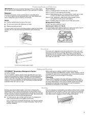
... and broil elements cycle on some models) The ACCUBAKE® system electronically regulates the oven heat levels during preheat and bake to maintain a precise temperature range for baking. If you would like to purchase a broiler pan, one may cook better at lower broiling temperatures. ■ For best results, use . Rack 4: Use...
... and broil elements cycle on some models) The ACCUBAKE® system electronically regulates the oven heat levels during preheat and bake to maintain a precise temperature range for baking. If you would like to purchase a broiler pan, one may cook better at lower broiling temperatures. ■ For best results, use . Rack 4: Use...


