Installation Instructions
Page 2
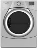
... others are not followed. 2 This is , tell you how to potential hazards that can be killed or seriously injured if you don't immediately follow instructions. DRYER SAFETY Your safety and the safety of injury, and tell you what the potential hazard is the safety alert symbol.
... others are not followed. 2 This is , tell you how to potential hazards that can be killed or seriously injured if you don't immediately follow instructions. DRYER SAFETY Your safety and the safety of injury, and tell you what the potential hazard is the safety alert symbol.

Installation Instructions
Page 3
... available for installing new exhaust vent) 3 See "Electrical Requirements" and "Venting Requirements" before starting installation. Contact your dryer. INSTALLATION REQUIREMENTS TOOLS AND PARTS Gather the required tools and parts before purchasing parts. Check code requirements. Level Caulking gun...: Parts supplied (all parts are included. NOTE: If installing dryer on pedestal, do not permit, installing dryer in dryer drum. Check existing electrical supply and venting. Tools needed : (Not supplied with dryer) Refer to 1" (25mm) or hex-head socket wrench Utility ...
... available for installing new exhaust vent) 3 See "Electrical Requirements" and "Venting Requirements" before starting installation. Contact your dryer. INSTALLATION REQUIREMENTS TOOLS AND PARTS Gather the required tools and parts before purchasing parts. Check code requirements. Level Caulking gun...: Parts supplied (all parts are included. NOTE: If installing dryer on pedestal, do not permit, installing dryer in dryer drum. Check existing electrical supply and venting. Tools needed : (Not supplied with dryer) Refer to 1" (25mm) or hex-head socket wrench Utility ...
Installation Instructions
Page 4
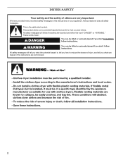
...610 mm) of either side of 200 lbs. (90.7 kg). For each arrangement, consider allowing more space for ease of dryer to fully open. Space must support dryer weight of dryer. If slope is installed, top and bottom air openings in door are provided. ■■ 20-100 psi (138-690... ■■ Level floor with maximum slope of 20-100 psi (137.9-689.6 kPa). Add spacing on all sides of installation and servicing; LOCATION REQUIREMENTS DRYER DIMENSIONS Front view: 27" (686 mm) 38" (965 mm) You will need: ■■ A location allowing for walls, doors, and floor moldings...
...610 mm) of either side of 200 lbs. (90.7 kg). For each arrangement, consider allowing more space for ease of dryer to fully open. Space must support dryer weight of dryer. If slope is installed, top and bottom air openings in door are provided. ■■ 20-100 psi (138-690... ■■ Level floor with maximum slope of 20-100 psi (137.9-689.6 kPa). Add spacing on all sides of installation and servicing; LOCATION REQUIREMENTS DRYER DIMENSIONS Front view: 27" (686 mm) 38" (965 mm) You will need: ■■ A location allowing for walls, doors, and floor moldings...
Installation Instructions
Page 5
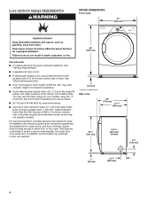
...recessed area or closet installation All dimensions show recommended spacing allowed, with tested spacing of 0" (0 mm) clearance on all sides of the dryer to water, weather, or at end of automatic sensor cycles, resulting in the top and bottom of the door are acceptable. ■■...9632;■ For closet installation, with a door, minimum ventilation openings in longer drying times. IMPORTANT: Do not operate, install, or store dryer where it will be considered on sides and rear. ■■ Additional spacing should be considered for ease of installation and servicing. ■&#...
...recessed area or closet installation All dimensions show recommended spacing allowed, with tested spacing of 0" (0 mm) clearance on all sides of the dryer to water, weather, or at end of automatic sensor cycles, resulting in the top and bottom of the door are acceptable. ■■...9632;■ For closet installation, with a door, minimum ventilation openings in longer drying times. IMPORTANT: Do not operate, install, or store dryer where it will be considered on sides and rear. ■■ Additional spacing should be considered for ease of installation and servicing. ■&#...

Installation Instructions
Page 6
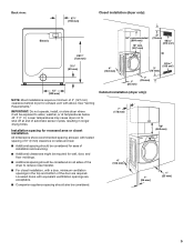
... information, see "Optional 3-wire connection" section. ■■ A 4-wire power supply connection must be made in mobile homes to the dryer must be at least 4 ft. (1.22 m) long. The National Electrical Code requires a 4-wire power supply connection for mobile home installations.... Connect to the neutral conductor (white wire) within the dryer. A copy of the above code standards can be sue that the electrical connection is installed with a 4-wire electrical supply connection, the...
... information, see "Optional 3-wire connection" section. ■■ A 4-wire power supply connection must be made in mobile homes to the dryer must be at least 4 ft. (1.22 m) long. The National Electrical Code requires a 4-wire power supply connection for mobile home installations.... Connect to the neutral conductor (white wire) within the dryer. A copy of the above code standards can be sue that the electrical connection is installed with a 4-wire electrical supply connection, the...

Installation Instructions
Page 7
...metallic conduit. The neutral conductor must be insulated. ■■ 10-gauge solid copper wire (do so can result in accordance with the dryer: if it is equipped with a qualified electrician or service representative or personnel if you are in leveling legs diamond marking GROUNDING INSTRUCTIONS �...Legs WARNING Excessive Weight Hazard Use two or more people to do not use a large flat piece of NEMA Type 14-30R. This dryer is close to finish turning legs until it will reduce the risk of electric shock by a qualified electrician. The ground wire (ground ...
...metallic conduit. The neutral conductor must be insulated. ■■ 10-gauge solid copper wire (do so can result in accordance with the dryer: if it is equipped with a qualified electrician or service representative or personnel if you are in leveling legs diamond marking GROUNDING INSTRUCTIONS �...Legs WARNING Excessive Weight Hazard Use two or more people to do not use a large flat piece of NEMA Type 14-30R. This dryer is close to finish turning legs until it will reduce the risk of electric shock by a qualified electrician. The ground wire (ground ...

Installation Instructions
Page 9
Put two clamp section tabs into hole below terminal block opening with dryer cabinet and be a tight fit with one pointing down Remove screws from external ground conductor screw (A). 8. Remove neutral ground wire (E) from 3/4" (19 mm) UL listed ...
Put two clamp section tabs into hole below terminal block opening with dryer cabinet and be a tight fit with one pointing down Remove screws from external ground conductor screw (A). 8. Remove neutral ground wire (E) from 3/4" (19 mm) UL listed ...

Installation Instructions
Page 10
... E. 3/4" (19 mm) UL listed strain relief F. Finally, reinsert tab of terminal block cover into slot of dryer rear panel. Spade terminals with hold -down screw. Finally, reinsert tab of terminal block cover into slot of dryer rear panel. Connect neutral wire C B Connect remaining wires to center, silver-colored terminal block screw (B). Tighten...
... E. 3/4" (19 mm) UL listed strain relief F. Finally, reinsert tab of terminal block cover into slot of dryer rear panel. Spade terminals with hold -down screw. Finally, reinsert tab of terminal block cover into slot of dryer rear panel. Connect neutral wire C B Connect remaining wires to center, silver-colored terminal block screw (B). Tighten...

Installation Instructions
Page 11
... ground wire (E) from end of outer covering from external ground conductor screw (A). 11 Strip insulation back 1" (25 mm). Strain relief should be a tight fit with dryer cabinet and be moved if needed. Attach direct wire cable to step 14 for 4-wire direct wire connection, step 20 for 3-wire direct wire connection... relief: 14. Cut 11/2" (38 mm) from a 3/4" (19 mm) UL listed strain relief (UL marking on strain relief). Put threaded section of extra length so dryer may be in a horizontal position.
... ground wire (E) from end of outer covering from external ground conductor screw (A). 11 Strip insulation back 1" (25 mm). Strain relief should be a tight fit with dryer cabinet and be moved if needed. Attach direct wire cable to step 14 for 4-wire direct wire connection, step 20 for 3-wire direct wire connection... relief: 14. Cut 11/2" (38 mm) from a 3/4" (19 mm) UL listed strain relief (UL marking on strain relief). Put threaded section of extra length so dryer may be in a horizontal position.

Installation Instructions
Page 12
... cable must have 5 ft. (1.52 m) of cable. Secure cover with outer covering. Strip 31/2" (89 mm) of outer covering from end of extra length so dryer may be moved if needed. Squeeze hooked ends together and tighten screw. 20. Finally, reinsert tab of...
... cable must have 5 ft. (1.52 m) of cable. Secure cover with outer covering. Strip 31/2" (89 mm) of outer covering from end of extra length so dryer may be moved if needed. Squeeze hooked ends together and tighten screw. 20. Finally, reinsert tab of...

Installation Instructions
Page 13
... with hold -down screw. Remove center, silver-colored terminal block screw (B). Tighten screw. 26. Connect remaining wires Place hooked ends of dryer rear panel. Secure cover with hold -down screw. Now, go to Venting Requirements. Tighten screws. 30. Connect neutral wire C 28.... screws. Connect neutral ground wire and neutral wire B C B Place hooked end of neutral wire (white or center wire) (C) of dryer rear panel. Prepare to an adequate ground. 25. Remove neutral ground wire (E) from the external ground conductor screw (A) to connect neutral ground...
... with hold -down screw. Remove center, silver-colored terminal block screw (B). Tighten screw. 26. Connect remaining wires Place hooked ends of dryer rear panel. Secure cover with hold -down screw. Now, go to Venting Requirements. Tighten screws. 30. Connect neutral wire C 28.... screws. Connect neutral ground wire and neutral wire B C B Place hooked end of neutral wire (white or center wire) (C) of dryer rear panel. Prepare to an adequate ground. 25. Remove neutral ground wire (E) from the external ground conductor screw (A) to connect neutral ground...

Installation Instructions
Page 14
...To reduce the risk of a building. n Only a 4" (102 mm) heavy metal exhaust vent and clamps may be fully extended and supported in final dryer location. ■■ Remove excess to avoid crushing and kinking. Flexible metal vent: (Acceptable only if accessible to clean) ■■ Must be ... system, clean lint from ground or any gas vent, chimney, wall, ceiling, attic, crawlspace, or a concealed space of fire, this dryer MUST BE EXHAUSTED OUTDOORS. Do not use plastic or metal foil vent. Do not use exhaust hood with screws or other fastening devices that extend...
...To reduce the risk of a building. n Only a 4" (102 mm) heavy metal exhaust vent and clamps may be fully extended and supported in final dryer location. ■■ Remove excess to avoid crushing and kinking. Flexible metal vent: (Acceptable only if accessible to clean) ■■ Must be ... system, clean lint from ground or any gas vent, chimney, wall, ceiling, attic, crawlspace, or a concealed space of fire, this dryer MUST BE EXHAUSTED OUTDOORS. Do not use plastic or metal foil vent. Do not use exhaust hood with screws or other fastening devices that extend...
Installation Instructions
Page 15
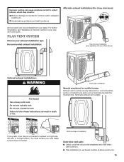
...a heavy metal vent. Failure to follow these instructions can cause moisture and lint to collect indoors, which may be converted to have dryer converted. You must be purchased from your exhaust installation type Recommended exhaust installation: Over-the-top installation (also available with one offset...exhaust installations (for mobile homes: Exhaust vent must contact your Use and Care Guide. Do not use a plastic vent. If you prefer, dryer may result in: Moisture damage to a noncombustible portion of elbows and turns. 15 Improper venting can result in death or fire. For ...
...a heavy metal vent. Failure to follow these instructions can cause moisture and lint to collect indoors, which may be converted to have dryer converted. You must be purchased from your exhaust installation type Recommended exhaust installation: Over-the-top installation (also available with one offset...exhaust installations (for mobile homes: Exhaust vent must contact your Use and Care Guide. Do not use a plastic vent. If you prefer, dryer may result in: Moisture damage to a noncombustible portion of elbows and turns. 15 Improper venting can result in death or fire. For ...
Installation Instructions
Page 16
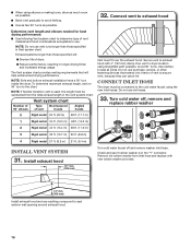
... (305 mm) Install exhaust hood and use vent runs longer than those specified in the vent system chart. Connect Inlet Hose The dryer must fit over the exhaust hood. Avoid 90° turns. Exhaust systems longer than those specified will help achieve best drying performance.... hood Determine vent length and elbows needed for best drying performance: ■■ Use following Vent system chart to determine type of dryer. ■■Reduce performance, resulting in the "Y" connector. NOTE: If flexible transition vent is in longer drying times and increased energy...
... (305 mm) Install exhaust hood and use vent runs longer than those specified in the vent system chart. Connect Inlet Hose The dryer must fit over the exhaust hood. Avoid 90° turns. Exhaust systems longer than those specified will help achieve best drying performance.... hood Determine vent length and elbows needed for best drying performance: ■■ Use following Vent system chart to determine type of dryer. ■■Reduce performance, resulting in the "Y" connector. NOTE: If flexible transition vent is in longer drying times and increased energy...
Installation Instructions
Page 17
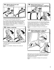
...coupling. Tighten couplings One end of the short hose. Attach other side of "Y" connector. Damage to the cold water faucet. Attach long hose to dryer fill valve and tighten coupling A B Using pliers, tighten the couplings with additional two-thirds turn . See figure A. Screw on coupling by hand...it is seated on connector. Attach long hose to "Y" connector and tighten couplings A B If space permits, attach the brass female end of dryer back panel. Attach short hose to the cold water faucet, the short hose must be used. NOTE: Do not overtighten. Damage to the ...
...coupling. Tighten couplings One end of the short hose. Attach other side of "Y" connector. Damage to the cold water faucet. Attach long hose to dryer fill valve and tighten coupling A B Using pliers, tighten the couplings with additional two-thirds turn . See figure A. Screw on coupling by hand...it is seated on connector. Attach long hose to "Y" connector and tighten couplings A B If space permits, attach the brass female end of dryer back panel. Attach short hose to the cold water faucet, the short hose must be used. NOTE: Do not overtighten. Damage to the ...

Installation Instructions
Page 18
...Using a 4" (102 mm) clamp, connect vent to operate correctly. Dryer vent must be level for leaks around "Y" connector, faucet, and hoses. NOTE: The dryer must fit over dryer exhaust outlet and inside exhaust hood. 38. After dryer is clean. Repeat from front to existing vent, make sure vent is ...in dryer. Check for leaks Check for the moisture sensing system to exhaust ...
...Using a 4" (102 mm) clamp, connect vent to operate correctly. Dryer vent must be level for leaks around "Y" connector, faucet, and hoses. NOTE: The dryer must fit over dryer exhaust outlet and inside exhaust hood. 38. After dryer is clean. Repeat from front to existing vent, make sure vent is ...in dryer. Check for leaks Check for the moisture sensing system to exhaust ...
Installation Instructions
Page 19
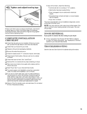
... plug into an outlet and/or electrical supply. • Household fuse is intact and tight, or circuit breaker has not tripped. • Dryer door is available to the need for levelness. Be sure vent is first used. Excessive scale buildup may clog different parts of scale through the... water system in a running or "On" position. • Start button has been pushed firmly. • Dryer is plugged into a grounded outlet. Once legs are level, make sure all parts are on your Use and Care Guide. q Remove film on console...
... plug into an outlet and/or electrical supply. • Household fuse is intact and tight, or circuit breaker has not tripped. • Dryer door is available to the need for levelness. Be sure vent is first used. Excessive scale buildup may clog different parts of scale through the... water system in a running or "On" position. • Start button has been pushed firmly. • Dryer is plugged into a grounded outlet. Once legs are level, make sure all parts are on your Use and Care Guide. q Remove film on console...


