Installation Instructions
Page 2
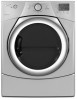
...important. All safety messages will follow instructions. These words mean: DANGER You can kill or hurt you don't follow the safety alert symbol and either the word "DANGER" or "WARNING." This symbol alerts you to reduce the chance of others . DRYER SAFETY Your safety and the safety of... injury, and tell you what the potential hazard is the safety alert symbol. Always read and obey all safety messages. We have provided many important safety messages in this manual and on your appliance.
...important. All safety messages will follow instructions. These words mean: DANGER You can kill or hurt you don't follow the safety alert symbol and either the word "DANGER" or "WARNING." This symbol alerts you to reduce the chance of others . DRYER SAFETY Your safety and the safety of... injury, and tell you what the potential hazard is the safety alert symbol. Always read and obey all safety messages. We have provided many important safety messages in this manual and on your appliance.

Installation Instructions
Page 3
... legs (4) Parts supplied (steam models): Wire stripper (direct wire installations) Tin snips (new vent installations) "Y" connector Short inlet hose 1/4" nut driver (recommended) Vent clamps Adjustable wrench that all parts are included. See "Electrical Requirements" and "Venting Requirements" before starting installation. Tools needed : (Not supplied with dryer) Refer to 1" (25mm) or hex-head socket wrench Utility knife Tape measure Pliers Long inlet hose Rubber washer Parts package is located in garages, closets, mobile homes, or sleeping quarters. Check code...
... legs (4) Parts supplied (steam models): Wire stripper (direct wire installations) Tin snips (new vent installations) "Y" connector Short inlet hose 1/4" nut driver (recommended) Vent clamps Adjustable wrench that all parts are included. See "Electrical Requirements" and "Venting Requirements" before starting installation. Tools needed : (Not supplied with dryer) Refer to 1" (25mm) or hex-head socket wrench Utility knife Tape measure Pliers Long inlet hose Rubber washer Parts package is located in garages, closets, mobile homes, or sleeping quarters. Check code...
Installation Instructions
Page 4
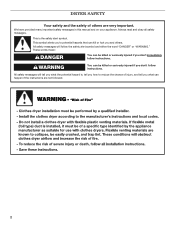
... fully open. spacing for companion appliances and clearances for proper exhaust installation. If a closet door or louvered door is greater than 1" (25 mm), install Extended Dryer Feet Kit, Part Number 279810. See "Electrical Requirements." ■■ Floor must be large enough to allow door to reduce noise transfer. If not level, clothes may not tumble properly and automatic sensor cycles may use the water supply for your washer using power supply cord, a grounded electrical outlet located...
... fully open. spacing for companion appliances and clearances for proper exhaust installation. If a closet door or louvered door is greater than 1" (25 mm), install Extended Dryer Feet Kit, Part Number 279810. See "Electrical Requirements." ■■ Floor must be large enough to allow door to reduce noise transfer. If not level, clothes may not tumble properly and automatic sensor cycles may use the water supply for your washer using power supply cord, a grounded electrical outlet located...
Installation Instructions
Page 5
... considered for ease of installation and servicing. ■■ Additional clearances might be required for exhaust vent with equivalent ventilitation openings are required. Louvered doors with elbow. See "Venting Requirements." IMPORTANT: Do not operate, install, or store dryer where it will be considered. 7" (178 mm) 18" (460 mm) 4" (102 mm) 1" (25 mm) 1" (25 mm) 5 Lower temperatures may cause dryer not to water, weather, or at end...
... considered for ease of installation and servicing. ■■ Additional clearances might be required for exhaust vent with equivalent ventilitation openings are required. Louvered doors with elbow. See "Venting Requirements." IMPORTANT: Do not operate, install, or store dryer where it will be considered. 7" (178 mm) 18" (460 mm) 4" (102 mm) 1" (25 mm) 1" (25 mm) 5 Lower temperatures may cause dryer not to water, weather, or at end...

Installation Instructions
Page 6
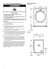
Mobile home installations require: ■■ Metal exhaust system hardware, available for purchase from your Use and Care Guide. ■■ Special provisions must be using a power supply cord: Use a UL listed power supply cord kit marked for mobile home installations. For further information, see "Optional 3-wire connection" section. ■■ A 4-wire power supply connection must be made in mobile homes to introduce outside air into dryer. The National Electrical Code requires a 4-wire power supply connection for Mobile home...
Mobile home installations require: ■■ Metal exhaust system hardware, available for purchase from your Use and Care Guide. ■■ Special provisions must be using a power supply cord: Use a UL listed power supply cord kit marked for mobile home installations. For further information, see "Optional 3-wire connection" section. ■■ A 4-wire power supply connection must be made in mobile homes to introduce outside air into dryer. The National Electrical Code requires a 4-wire power supply connection for Mobile home...

Installation Instructions
Page 7
... panel) and gently lay dryer down on its final location. The plug must have four 10-gauge copper wires and match a 4-wire receptacle of NEMA Type 14-30R. Failure to connect the exhaust vent. 7 To avoid damaging floor, use a large flat piece of dryer. grounding conductor can result in leveling legs diamond marking GROUNDING INSTRUCTIONS � For a grounded, cord-connected dryer: This dryer must be identified by direct wire: Power...
... panel) and gently lay dryer down on its final location. The plug must have four 10-gauge copper wires and match a 4-wire receptacle of NEMA Type 14-30R. Failure to connect the exhaust vent. 7 To avoid damaging floor, use a large flat piece of dryer. grounding conductor can result in leveling legs diamond marking GROUNDING INSTRUCTIONS � For a grounded, cord-connected dryer: This dryer must be identified by direct wire: Power...

Installation Instructions
Page 8
... copper wire. Then go to green ground connector. use a new ul listed 30 amp power supply cord. Ground wire (green or bare wire) must be connected to Venting Requirements. 3-wire direct connection: Follow steps 4, 14-15, and 22-26. Electrical Connection Options 3. Remove hold-down screw and terminal block cover. Ground wire (green or bare wire) must be used with either a power supply cord or a direct wire connection. 8 4. Connect remaining 2 supply wires to center terminal (silver). Choose electrical connection type Power supply cord 4-wire receptacle (NEMA Type 14...
... copper wire. Then go to green ground connector. use a new ul listed 30 amp power supply cord. Ground wire (green or bare wire) must be connected to Venting Requirements. 3-wire direct connection: Follow steps 4, 14-15, and 22-26. Electrical Connection Options 3. Remove hold-down screw and terminal block cover. Ground wire (green or bare wire) must be used with either a power supply cord or a direct wire connection. 8 4. Connect remaining 2 supply wires to center terminal (silver). Choose electrical connection type Power supply cord 4-wire receptacle (NEMA Type 14...

Installation Instructions
Page 9
... 4-wire power supply cord connection or step 9 for mobile homes and where local codes do not permit the use of power supply cord under center, silvercolored terminal block screw (B). Tighten screw. 9 Spade terminals with dryer cabinet and be a tight fit with upturned ends F. 3/4" (19 mm) UL listed strain relief G. Connect neutral ground wire (E) and neutral wire (white or center wire) (C) of 3-wire connections. Hold in a horizontal position. Remove neutral ground wire...
... 4-wire power supply cord connection or step 9 for mobile homes and where local codes do not permit the use of power supply cord under center, silvercolored terminal block screw (B). Tighten screw. 9 Spade terminals with dryer cabinet and be a tight fit with upturned ends F. 3/4" (19 mm) UL listed strain relief G. Connect neutral ground wire (E) and neutral wire (white or center wire) (C) of 3-wire connections. Hold in a horizontal position. Remove neutral ground wire...

Installation Instructions
Page 10
... block screw (B). Neutral prong D. Neutral (white or center wire) Connect neutral wire (white or center wire) (C) of dryer rear panel. Tighten screw. 10. Spade terminals with upturned ends E. 3/4" (19 mm) UL listed strain relief F. Connect remaining wires Connect remaining wires to outer terminal block screws. Tighten screws. Finally, reinsert tab of terminal block cover into slot of power supply cord to external ground conductor screw (A). Now, go to Venting Requirements. 3-wire Power supply cord Connection Use where local codes permit connecting...
... block screw (B). Neutral prong D. Neutral (white or center wire) Connect neutral wire (white or center wire) (C) of dryer rear panel. Tighten screw. 10. Spade terminals with upturned ends E. 3/4" (19 mm) UL listed strain relief F. Connect remaining wires Connect remaining wires to outer terminal block screws. Tighten screws. Finally, reinsert tab of terminal block cover into slot of power supply cord to external ground conductor screw (A). Now, go to Venting Requirements. 3-wire Power supply cord Connection Use where local codes permit connecting...

Installation Instructions
Page 11
... terminal block Put direct wire cable through hole below terminal block opening, screw removable conduit connector onto strain relief threads. 15. Tighten strain relief screw against direct wire cable. Remove neutral ground wire (E) from end of strain relief through strain relief. Attach direct wire cable to strain relief (127 5" mm) Direct wire cable must have 5 ft. (1.52 m) of wire under terminal block screw, facing to terminal block, place hooked end of extra length so dryer...
... terminal block Put direct wire cable through hole below terminal block opening, screw removable conduit connector onto strain relief threads. 15. Tighten strain relief screw against direct wire cable. Remove neutral ground wire (E) from end of strain relief through strain relief. Attach direct wire cable to strain relief (127 5" mm) Direct wire cable must have 5 ft. (1.52 m) of wire under terminal block screw, facing to terminal block, place hooked end of extra length so dryer...

Installation Instructions
Page 12
19. Connect ground wire F 3-wire Direct WIRE Connection Use where local codes permit connecting cabinet-ground conductor to Venting Requirements. Strip 31/2" (89 mm) of outer covering from end of terminal block (B). If using 3-wire cable with ground wire, cut bare wire even with hold-down screw. Shape wire ends into slot of wire under terminal block screw, facing to terminal block, place hooked end of dryer rear panel. Squeeze hooked ends together and tighten screws. Remove center, silver-colored terminal block screw...
19. Connect ground wire F 3-wire Direct WIRE Connection Use where local codes permit connecting cabinet-ground conductor to Venting Requirements. Strip 31/2" (89 mm) of outer covering from end of terminal block (B). If using 3-wire cable with ground wire, cut bare wire even with hold-down screw. Shape wire ends into slot of wire under terminal block screw, facing to terminal block, place hooked end of dryer rear panel. Squeeze hooked ends together and tighten screws. Remove center, silver-colored terminal block screw...

Installation Instructions
Page 13
.... Finally, reinsert tab of terminal block cover into slot of direct wire cable under outer terminal block screws (hooks facing right). Now, go to Venting Requirements. Tighten screws. 30. Tighten screw. 29. Connect neutral ground wire and neutral wire B C B Place hooked end of neutral wire (white or center wire) (C) of dryer rear panel. Finally, reinsert tab of terminal block cover into slot of remaining wires under center terminal block screw (B). Remove neutral ground wire (E) from the external ground...
.... Finally, reinsert tab of terminal block cover into slot of direct wire cable under outer terminal block screws (hooks facing right). Now, go to Venting Requirements. Tighten screws. 30. Tighten screw. 29. Connect neutral ground wire and neutral wire B C B Place hooked end of neutral wire (white or center wire) (C) of dryer rear panel. Finally, reinsert tab of terminal block cover into slot of remaining wires under center terminal block screw (B). Remove neutral ground wire (E) from the external ground...

Installation Instructions
Page 14
...; Use clamps to clean) ■■ Must be connected or secured with lint. Do not use a heavy metal vent. B 4" C A (102 mm) 4" (102 mm) 4" (102 mm) Recommended styles: A. Angled hood ■■ An exhaust hood should not exceed 73/4 ft. (2.4 m). Flexible metal vent: (Acceptable only if accessible to seal all governing codes and ordinances. Replace plastic or metal foil vents with a magnetic latch. Venting REQUiREMENTS...
...; Use clamps to clean) ■■ Must be connected or secured with lint. Do not use a heavy metal vent. B 4" C A (102 mm) 4" (102 mm) 4" (102 mm) Recommended styles: A. Angled hood ■■ An exhaust hood should not exceed 73/4 ft. (2.4 m). Flexible metal vent: (Acceptable only if accessible to seal all governing codes and ordinances. Replace plastic or metal foil vents with a magnetic latch. Venting REQUiREMENTS...
Installation Instructions
Page 15
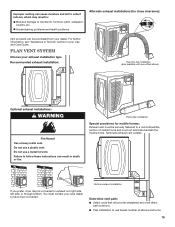
... to use a metal foil vent. Improper venting can result in death or fire. PLAN VENT SYSTEM Choose your Use and Care Guide. Terminate exhaust vent outside. Bottom exhaust installation Determine vent path: ■■ Select route that will provide straightest and most direct path outdoors. ■■ Plan installation to a noncombustible portion of elbows and turns. 15 Housecleaning problems and health problems. Alternate exhaust installations (for mobile homes: Exhaust vent must be converted...
... to use a metal foil vent. Improper venting can result in death or fire. PLAN VENT SYSTEM Choose your Use and Care Guide. Terminate exhaust vent outside. Bottom exhaust installation Determine vent path: ■■ Select route that will provide straightest and most direct path outdoors. ■■ Plan installation to a noncombustible portion of elbows and turns. 15 Housecleaning problems and health problems. Alternate exhaust installations (for mobile homes: Exhaust vent must be converted...
Installation Instructions
Page 16
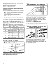
... determine maximum exhaust length, add on 90° turn inside the dryer. Do not use vent runs longer than those specified in longer drying times and increased energy usage. Check and see if rubber washer is used, the length must fit over the exhaust hood. NOTE: If flexible transition vent is in the vent system chart. Run vent to secure vent, because they can catch lint. Turn cold water off and remove washer inlet hose. Exhaust systems...
... determine maximum exhaust length, add on 90° turn inside the dryer. Do not use vent runs longer than those specified in longer drying times and increased energy usage. Check and see if rubber washer is used, the length must fit over the exhaust hood. NOTE: If flexible transition vent is in the vent system chart. Run vent to secure vent, because they can catch lint. Turn cold water off and remove washer inlet hose. Exhaust systems...
Installation Instructions
Page 17
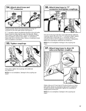
...valve connector. Screw on coupling by hand until it is seated on connector. Using pliers, tighten the couplings an additional two-thirds turn . Attach washer cold inlet hose to other end of long hose to brass male end of dryer back panel. Attach long hose to the "Y" connector. See figure A. Then attach "Y" connector to fill valve...of the long hose has a wire mesh strainer inside the coupling. NOTE: Do not overtighten. Using pliers, tighten the couplings an additional two-thirds turn . Damage to the cold water faucet. 34. Attach long hose to "Y" connector and ...
...valve connector. Screw on coupling by hand until it is seated on connector. Using pliers, tighten the couplings an additional two-thirds turn . Attach washer cold inlet hose to other end of long hose to brass male end of dryer back panel. Attach long hose to the "Y" connector. See figure A. Then attach "Y" connector to fill valve...of the long hose has a wire mesh strainer inside the coupling. NOTE: Do not overtighten. Using pliers, tighten the couplings an additional two-thirds turn . Damage to the cold water faucet. 34. Attach long hose to "Y" connector and ...

Installation Instructions
Page 18
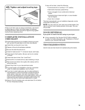
... turned on cold water faucet 41. Level dryer 42. Turn on . 39. Check for leaks Check for the moisture sensing system to side. If connecting to crush or kink vent. 38. Connect vent to exhaust outlet Move dryer to final location, taking care not to existing vent, make sure vent is clean. Using a 4" (102 mm) clamp, connect vent to back. Level Dryer Place level here Check levelness of dryer from front to exhaust outlet in place, remove...
... turned on cold water faucet 41. Level dryer 42. Turn on . 39. Check for leaks Check for the moisture sensing system to side. If connecting to crush or kink vent. 38. Connect vent to exhaust outlet Move dryer to final location, taking care not to existing vent, make sure vent is clean. Using a 4" (102 mm) clamp, connect vent to back. Level Dryer Place level here Check levelness of dryer from front to exhaust outlet in place, remove...
Installation Instructions
Page 19
... select Air Only Temperature setting. Complete Installation CHECKLIST q Check that you have all parts are set in a running or "On" position. • Start button has been pushed firmly. • Dryer is plugged into a grounded outlet. q Check that all of lime scale may notice an odor when dryer is available to the need for levelness. See "Level Dryer". q If you prefer to reverse the door swing on Power. Troubleshooting See the Use and Care Guide...
... select Air Only Temperature setting. Complete Installation CHECKLIST q Check that you have all parts are set in a running or "On" position. • Start button has been pushed firmly. • Dryer is plugged into a grounded outlet. q Check that all of lime scale may notice an odor when dryer is available to the need for levelness. See "Level Dryer". q If you prefer to reverse the door swing on Power. Troubleshooting See the Use and Care Guide...

Installation Instructions
Page 20
W10240579B W10240583B-SP © 2009 2Al0l rights reserved 12/09 Printed in U.S.A.
W10240579B W10240583B-SP © 2009 2Al0l rights reserved 12/09 Printed in U.S.A.


