Use and Care Guide
Page 4
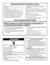
... plug in water. ■ Keep cord away from heated surfaces. ■ Do not let cord hang over edge of table or counter. ■ Do not mount over a sink. ■ Do not cover racks or any other than manufacturer's recommended accessories, in harmful exposure to accumulate on . ■ Use care when cleaning...
... plug in water. ■ Keep cord away from heated surfaces. ■ Do not let cord hang over edge of table or counter. ■ Do not mount over a sink. ■ Do not cover racks or any other than manufacturer's recommended accessories, in harmful exposure to accumulate on . ■ Use care when cleaning...
Use and Care Guide
Page 13
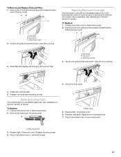
...Install new charcoal filter. 5. Close bulb cover. 6. Replace light. Vent grille B. A B C 3. To Replace: 1. Remove the bulb cover mounting screw. Plug in microwave oven or reconnect power. 13 To Remove and Replace Charcoal Filter: 1. Tip the vent grille forward and down , then ...filter back slightly, lift front end, and pull out filter. See "Assistance or Service" section to remove. 4. Replace light. Mounting screw 3. Mounting screws 3. Lift up the bulb cover. 4. A. Tip the vent grille forward and down , then lift to reorder. Replacing Cooktop...
...Install new charcoal filter. 5. Close bulb cover. 6. Replace light. Vent grille B. A B C 3. To Replace: 1. Remove the bulb cover mounting screw. Plug in microwave oven or reconnect power. 13 To Remove and Replace Charcoal Filter: 1. Tip the vent grille forward and down , then ...filter back slightly, lift front end, and pull out filter. See "Assistance or Service" section to remove. 4. Replace light. Mounting screw 3. Mounting screws 3. Lift up the bulb cover. 4. A. Tip the vent grille forward and down , then lift to reorder. Replacing Cooktop...
Installation Instructions
Page 1
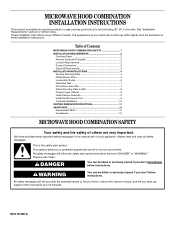
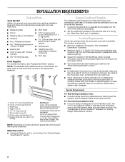
...1 INSTALLATION REQUIREMENTS 2 Tools and Parts 2 Remove Cardboard Template 2 Location Requirements 2 Product Dimensions 3 Electrical Requirements 3 INSTALLATION INSTRUCTIONS 4 Remove Mounting Plate 4 Rotate Blower Motor 4 Locate Wall Stud(s 6 Mark Rear Wall 7 Drill Holes in these installation instructions. WARNING You can kill... messages in this manual and on your particular model may differ slightly from the illustration in Rear Wall 7 Attach Mounting Plate to potential hazards that can be killed or seriously injured if you don't immediately follow the safety alert symbol...
...1 INSTALLATION REQUIREMENTS 2 Tools and Parts 2 Remove Cardboard Template 2 Location Requirements 2 Product Dimensions 3 Electrical Requirements 3 INSTALLATION INSTRUCTIONS 4 Remove Mounting Plate 4 Rotate Blower Motor 4 Locate Wall Stud(s 6 Mark Rear Wall 7 Drill Holes in these installation instructions. WARNING You can kill... messages in this manual and on your particular model may differ slightly from the illustration in Rear Wall 7 Attach Mounting Plate to potential hazards that can be killed or seriously injured if you don't immediately follow the safety alert symbol...
Installation Instructions
Page 2
... 6" (15.2 cm) of installation. See "Rectangular to withstand the heat produced by the microwave oven for wall or roof venting) Not Shown: Upper cabinet template Mounting plate (attached to separate the template from the top of any tools listed here. ■ Measuring tape ■ Stud finder ■ Pencil ■ 7/16" socket...
... 6" (15.2 cm) of installation. See "Rectangular to withstand the heat produced by the microwave oven for wall or roof venting) Not Shown: Upper cabinet template Mounting plate (attached to separate the template from the top of any tools listed here. ■ Measuring tape ■ Stud finder ■ Pencil ■ 7/16" socket...

Installation Instructions
Page 4
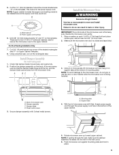
... Motor The microwave oven is being handled. Slide damper plate toward the front of microwave oven 3. A Screws B. Blower motor 4 Remove the mounting plate and set aside. 3. Tape the microwave oven door closed so that door does not swing open while the microwave oven is set for ...recirculation installation. Damper plate 2. Remove any remaining contents from the microwave oven cavity. 2. Back of the microwave oven and lift up. Mounting plate B. NOTE: To avoid damage to the microwave oven, do not grip or use the door or door handle while the microwave oven ...
... Motor The microwave oven is being handled. Slide damper plate toward the front of microwave oven 3. A Screws B. Blower motor 4 Remove the mounting plate and set aside. 3. Tape the microwave oven door closed so that door does not swing open while the microwave oven is set for ...recirculation installation. Damper plate 2. Remove any remaining contents from the microwave oven cavity. 2. Back of the microwave oven and lift up. Mounting plate B. NOTE: To avoid damage to the microwave oven, do not grip or use the door or door handle while the microwave oven ...
Installation Instructions
Page 6
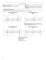
...show examples of each stud, and draw a plumb line down each stud center. Holes for lag screws E. Wall stud centerlines D. Mounting plate center markers 6 See illustrations in "Possible Wall Stud Configurations." No Wall Studs at End Holes Figure 1 No Wall Studs ...at Both End Holes Figure 4 B D B A A,D A,D A,D E E E E C C C C F F A. End holes (on mounting plate) B. Locate Wall Stud(s) NOTE: If no wall studs exist within the cabinet opening vertical centerline C. Using a stud finder, locate the edges of the vertical...
...show examples of each stud, and draw a plumb line down each stud center. Holes for lag screws E. Wall stud centerlines D. Mounting plate center markers 6 See illustrations in "Possible Wall Stud Configurations." No Wall Studs at End Holes Figure 1 No Wall Studs ...at Both End Holes Figure 4 B D B A A,D A,D A,D E E E E C C C C F F A. End holes (on mounting plate) B. Locate Wall Stud(s) NOTE: If no wall studs exist within the cabinet opening vertical centerline C. Using a stud finder, locate the edges of the vertical...
Installation Instructions
Page 7
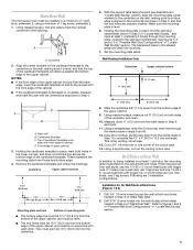
...drawn in place, find and clearly mark the vertical centerline of cabinet. D A C B A. Rear wall B. Front edge of "Mark Rear Wall." 2. Holding the mounting plate in Step 2 of the cutout area. 14. Drill 3/16" (5 mm) hole(s) into the wall stud(s) at End Holes (Figures 1 & 2) 1. ... A. Top of cardboard template must be 17¹⁄₄" (43.8 cm) from the bottom of 1 lag screw, preferably 2. 1. Set the mounting plate aside. Draw the 2 vertical, plumb lines down from the bottom edge of "Mark Rear Wall." Installation for No Wall Studs at the hole(s) ...
...drawn in place, find and clearly mark the vertical centerline of cabinet. D A C B A. Rear wall B. Front edge of "Mark Rear Wall." 2. Holding the mounting plate in Step 2 of the cutout area. 14. Drill 3/16" (5 mm) hole(s) into the wall stud(s) at End Holes (Figures 1 & 2) 1. ... A. Top of cardboard template must be 17¹⁄₄" (43.8 cm) from the bottom of 1 lag screw, preferably 2. 1. Set the mounting plate aside. Draw the 2 vertical, plumb lines down from the bottom edge of "Mark Rear Wall." Installation for No Wall Studs at the hole(s) ...

Installation Instructions
Page 8
...in the "Drill Holes in Rear Wall" section. 2. Drywall D. Drill a 3/4" (19 mm) hole through both ends. 1. Position mounting plate on the wall. 2. Position mounting plate on the wall. 4. Make sure the template centerline aligns with toggle nut through the drywall, and finger tighten the bolts to points... to go through the wall and to open . Insert a lag screw into the studs at the end holes marked in Step 6 of mounting plate, making sure it is level. 4. Remove all lag screws and bolts. Check alignment of "Mark Rear Wall." Leave enough space for...
...in the "Drill Holes in Rear Wall" section. 2. Drywall D. Drill a 3/4" (19 mm) hole through both ends. 1. Position mounting plate on the wall. 2. Position mounting plate on the wall. 4. Make sure the template centerline aligns with toggle nut through the drywall, and finger tighten the bolts to points... to go through the wall and to open . Insert a lag screw into the studs at the end holes marked in Step 6 of mounting plate, making sure it is level. 4. Remove all lag screws and bolts. Check alignment of "Mark Rear Wall." Leave enough space for...
Installation Instructions
Page 9
... the microwave oven gently. 1. Make sure the microwave oven door is the heavy side. Back of the upper cabinet. 5. Mounting plate B. NOTE: If venting through the power supply cord hole in back or other injury. Push microwave oven against... mounting plate and hold in the wall cutout. 6. This hole is metal, the supply cord bushing needs to the... flat-head bolt and place inside upper cabinet near the 3/8" (10 mm) holes. 2. Place a washer on the back of mounting plate.
... the microwave oven gently. 1. Make sure the microwave oven door is the heavy side. Back of the upper cabinet. 5. Mounting plate B. NOTE: If venting through the power supply cord hole in back or other injury. Push microwave oven against... mounting plate and hold in the wall cutout. 6. This hole is metal, the supply cord bushing needs to the... flat-head bolt and place inside upper cabinet near the 3/8" (10 mm) holes. 2. Place a washer on the back of mounting plate.
Installation Instructions
Page 10
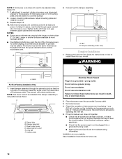
...assembly C. Do not use an extension cord. Failure to damper assembly. Check the operation of microwave oven by operating the vent fan. 5. Adjust mounting plate and retighten screws. 9. The blocks must be installed if the damper assembly is now complete. Vent B. Bolts For Roof Venting Installation Only ...oven downward. Test vent fan and exhaust by placing 1 cup (250 mL) of water on the turntable, and programming a cook time of mounting plate, and set aside on how to provide) may require bolts longer or shorter than 3" (7.6 cm). If adjustment is no gap between the...
...assembly C. Do not use an extension cord. Failure to damper assembly. Check the operation of microwave oven by operating the vent fan. 5. Adjust mounting plate and retighten screws. 9. The blocks must be installed if the damper assembly is now complete. Vent B. Bolts For Roof Venting Installation Only ...oven downward. Test vent fan and exhaust by placing 1 cup (250 mL) of water on the turntable, and programming a cook time of mounting plate, and set aside on how to provide) may require bolts longer or shorter than 3" (7.6 cm). If adjustment is no gap between the...
Installation Instructions
Page 12
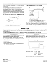
... to round transition piece = 5 ft (1.5 m) D. 2 ft (0.6 m) + 6 ft (1.8 m) straight = 8 ft (2.4 m) If the existing vent is located behind the door. ■ Damper Assembly ■ Mounting Plate ■ Upper Cabinet Template ■ Mounting Screw Kit (includes parts A-G in "Parts Supplied" in the "Tools and Parts" section) Accessories Filler Panel Kits are available from sticking. W10191951A...
... to round transition piece = 5 ft (1.5 m) D. 2 ft (0.6 m) + 6 ft (1.8 m) straight = 8 ft (2.4 m) If the existing vent is located behind the door. ■ Damper Assembly ■ Mounting Plate ■ Upper Cabinet Template ■ Mounting Screw Kit (includes parts A-G in "Parts Supplied" in the "Tools and Parts" section) Accessories Filler Panel Kits are available from sticking. W10191951A...
