Dimension Guide
Page 1
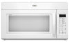
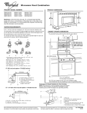
..." ) ' " (76.0 cm) CABINET OPENING DIMENSIONS The grounded 3-prong outlet must not exceed the equivalent of 140 ft (42.7 m) for planning purposes only. Ref. ® Microwave Hood Combination PRODUCT MODEL NUMBERS GMH3204XV GMH5205XV GMH6185XV WMH1162XV WMH1163XV WMH1164XW WMH2175XV WMH2205XV WMH3205XV Electrical: A 120-Volt, 60-Hz, AC-only, 15- A time-delay fuse or time-delay circuit breaker is recommended that the damper can open freely and fully...
..." ) ' " (76.0 cm) CABINET OPENING DIMENSIONS The grounded 3-prong outlet must not exceed the equivalent of 140 ft (42.7 m) for planning purposes only. Ref. ® Microwave Hood Combination PRODUCT MODEL NUMBERS GMH3204XV GMH5205XV GMH6185XV WMH1162XV WMH1163XV WMH1164XW WMH2175XV WMH2205XV WMH3205XV Electrical: A 120-Volt, 60-Hz, AC-only, 15- A time-delay fuse or time-delay circuit breaker is recommended that the damper can open freely and fully...

Installation Instructions
Page 1
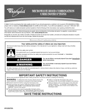
..." section for use above electric or gas cooking products up to Wall 8 Prepare Upper Cabinet 8 Install Damper Assembly 9 Install the Microwave Oven 9 Complete Installation 10 VENTING DESIGN SPECIFICATIONS 11 ASSISTANCE 12 Replacement Parts 12 Accessories 12 MICROWAVE HOOD COMBINATION SAFETY Your safety and the safety of your particular model may differ slightly from the illustration in this manual and on your appliance. All safety messages will follow instructions. These installation instructions cover different models. This symbol...
..." section for use above electric or gas cooking products up to Wall 8 Prepare Upper Cabinet 8 Install Damper Assembly 9 Install the Microwave Oven 9 Complete Installation 10 VENTING DESIGN SPECIFICATIONS 11 ASSISTANCE 12 Replacement Parts 12 Accessories 12 MICROWAVE HOOD COMBINATION SAFETY Your safety and the safety of your particular model may differ slightly from the illustration in this manual and on your appliance. All safety messages will follow instructions. These installation instructions cover different models. This symbol...

Installation Instructions
Page 2
... obstructions so that the door can open fully. ■ Some cabinet and building materials are not designed to use as a rear wall template. 1. Special Requirements For Wall Venting Installation Only: ■ Cutout must provide: ■ Minimum installation dimensions. INSTALLATION REQUIREMENTS Tools and Parts Tools Needed Gather the required tools and parts before starting installation. Sheet metal screws (2) G. See User Instructions.) NOTE: Depending on model, charcoal filters may be combined. See "Venting Design Specifications" section. The location must be included...
... obstructions so that the door can open fully. ■ Some cabinet and building materials are not designed to use as a rear wall template. 1. Special Requirements For Wall Venting Installation Only: ■ Cutout must provide: ■ Minimum installation dimensions. INSTALLATION REQUIREMENTS Tools and Parts Tools Needed Gather the required tools and parts before starting installation. Sheet metal screws (2) G. See User Instructions.) NOTE: Depending on model, charcoal filters may be combined. See "Venting Design Specifications" section. The location must be included...

Installation Instructions
Page 3
... dimensions may vary depending on type of electric shock by providing an escape wire for 66" (167.6 cm) installation height. If the power supply cord is typical for the electric current. See "Electrical Requirements" section. Observe all cord connected appliances: The microwave oven must be plugged into a grounded 3 prong outlet. Recommended: ■ A time-delay fuse or time-delay circuit breaker. ■ A separate circuit serving only this microwave oven...
... dimensions may vary depending on type of electric shock by providing an escape wire for 66" (167.6 cm) installation height. If the power supply cord is typical for the electric current. See "Electrical Requirements" section. Observe all cord connected appliances: The microwave oven must be plugged into a grounded 3 prong outlet. Recommended: ■ A time-delay fuse or time-delay circuit breaker. ■ A separate circuit serving only this microwave oven...

Installation Instructions
Page 4
... damper plate tabs are using recirculation installation. INSTALLATION INSTRUCTIONS Remove Mounting Plate Depending on your model, the mounting plate may be in the top of the microwave oven. Slide damper plate toward the front of microwave oven exterior. Reattach damper plate. Wall Venting Installation Only 1. Exhaust port 6. Slots 8. Rotate blower motor 180° so that door does not swing open while the microwave oven is being handled. 4. NOTE: Skip this section if you are inserted into the microwave oven. Screws (in another location where wall...
... damper plate tabs are using recirculation installation. INSTALLATION INSTRUCTIONS Remove Mounting Plate Depending on your model, the mounting plate may be in the top of the microwave oven. Slide damper plate toward the front of microwave oven exterior. Reattach damper plate. Wall Venting Installation Only 1. Exhaust port 6. Slots 8. Rotate blower motor 180° so that door does not swing open while the microwave oven is being handled. 4. NOTE: Skip this section if you are inserted into the microwave oven. Screws (in another location where wall...

Installation Instructions
Page 6
... microwave oven. 1. Using a stud finder, locate the edges of preferred installation configurations with the mounting plate. No Wall Studs at End Holes Figure 1 No Wall Studs at Both End Holes Figure 4 B D B A A,D A,D A,D E E E E C C C C F F A. See illustrations in "Possible Wall Stud Configurations." Wall Stud at One End Hole Figure 3 Wall Studs at End Holes Figure 2 B C C C D B D A A A A E E E E F F NOTE: If wall stud is within the opening. Holes for lag screws E. Mounting plate center markers 6 Support...
... microwave oven. 1. Using a stud finder, locate the edges of preferred installation configurations with the mounting plate. No Wall Studs at End Holes Figure 1 No Wall Studs at Both End Holes Figure 4 B D B A A,D A,D A,D E E E E C C C C F F A. See illustrations in "Possible Wall Stud Configurations." Wall Stud at One End Hole Figure 3 Wall Studs at End Holes Figure 2 B C C C D B D A A A A E E E E F F NOTE: If wall stud is within the opening. Holes for lag screws E. Mounting plate center markers 6 Support...

Installation Instructions
Page 7
... in Rear Wall In addition to being installed on at least 1 wall stud, the mounting plate must attach to the wall at the hole(s) marked in "Locate Wall Stud(s)" section. Using measuring tape, find the wall stud centerline(s) drawn in Step 2 of the cutout area. 14. Centerline 2. Front edge of the centerline, and mark. 10. Remove the cardboard template and check the markings: Upper cabinet bottom...
... in Rear Wall In addition to being installed on at least 1 wall stud, the mounting plate must attach to the wall at the hole(s) marked in "Locate Wall Stud(s)" section. Using measuring tape, find the wall stud centerline(s) drawn in Step 2 of the cutout area. 14. Centerline 2. Front edge of the centerline, and mark. 10. Remove the cardboard template and check the markings: Upper cabinet bottom...

Installation Instructions
Page 8
... have opened against drywall. Securely tighten the lag screws. Make sure the 10" (25.4 cm) dimension from upper cabinet. 3. Refer to outlet. 2. Check alignment of mounting plate, making sure it is level. 4. Prepare Upper Cabinet 1. Disconnect power to illustrations in "Possible Wall Stud Configurations" in "Locate Wall Stud(s)" section. Make sure the template centerline aligns with toggle nuts through the wall and to use as guides...
... have opened against drywall. Securely tighten the lag screws. Make sure the 10" (25.4 cm) dimension from upper cabinet. 3. Refer to outlet. 2. Check alignment of mounting plate, making sure it is level. 4. Prepare Upper Cabinet 1. Disconnect power to illustrations in "Possible Wall Stud Configurations" in "Locate Wall Stud(s)" section. Make sure the template centerline aligns with toggle nuts through the wall and to use as guides...

Installation Instructions
Page 9
... at the bottom of the microwave oven so that damper blade moves freely, and opens fully. 2. For Roof Venting Installation Only 7. Install Damper Assembly (for the power supply cord. IMPORTANT: The control side of microwave oven B. Make sure the microwave oven door is the heavy side. Secure damper assembly with 2 sheet metal screws. Failure to do not grip or use the door or door handle while the microwave oven is metal, the supply cord bushing needs to the upper cabinet.
... at the bottom of the microwave oven so that damper blade moves freely, and opens fully. 2. For Roof Venting Installation Only 7. Install Damper Assembly (for the power supply cord. IMPORTANT: The control side of microwave oven B. Make sure the microwave oven door is the heavy side. Secure damper assembly with 2 sheet metal screws. Failure to do not grip or use the door or door handle while the microwave oven is metal, the supply cord bushing needs to the upper cabinet.

Installation Instructions
Page 10
... mounting plate, and set aside on the turntable, and programming a cook time of the damper plate. With the microwave oven centered, and with sheet metal screw. A 2. Raised tabs B. Upper cabinet cutout E. Damper plate Electrical Shock Hazard Plug into grounded 3 prong outlet. 3. Damper assembly (under the raised tabs of 1 minute at 100% power. NOTE: The screw cannot be the same thickness as shown. Check the operation of water on a covered surface. 8. A B A. Refer to the User Instructions for troubleshooting...
... mounting plate, and set aside on the turntable, and programming a cook time of the damper plate. With the microwave oven centered, and with sheet metal screw. A 2. Raised tabs B. Upper cabinet cutout E. Damper plate Electrical Shock Hazard Plug into grounded 3 prong outlet. 3. Damper assembly (under the raised tabs of 1 minute at 100% power. NOTE: The screw cannot be the same thickness as shown. Check the operation of water on a covered surface. 8. A B A. Refer to the User Instructions for troubleshooting...

Installation Instructions
Page 12
... located behind the door. ■ Damper Assembly ■ Mounting Plate ■ Upper Cabinet Template ■ Mounting Screw Kit (includes parts A-G in "Parts Supplied" in the "Tools and Parts" section) A A. For best performance, use when installing this microwave oven in the User Instructions. All rights reserved. 461965617428 9/10 Printed in pairs. In addition, a rectangular 3" (7.6 cm) extension vent between the damper assembly and rectangular to round transition piece must be replaced, call us at our toll free number listed...
... located behind the door. ■ Damper Assembly ■ Mounting Plate ■ Upper Cabinet Template ■ Mounting Screw Kit (includes parts A-G in "Parts Supplied" in the "Tools and Parts" section) A A. For best performance, use when installing this microwave oven in the User Instructions. All rights reserved. 461965617428 9/10 Printed in pairs. In addition, a rectangular 3" (7.6 cm) extension vent between the damper assembly and rectangular to round transition piece must be replaced, call us at our toll free number listed...
Owners Manual
Page 1
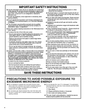
... abertura del horno de microondas, detrás de la puerta. Always read and obey all instructions before using electrical appliances basic safety precautions should be killed or seriously injured if you still need your model and serial number located on your appliance. All safety messages will need assistance, call us at www.whirlpool.com for additional information. IMPORTANT SAFETY INSTRUCTIONS When using the microwave oven. ■...
... abertura del horno de microondas, detrás de la puerta. Always read and obey all instructions before using electrical appliances basic safety precautions should be killed or seriously injured if you still need your model and serial number located on your appliance. All safety messages will need assistance, call us at www.whirlpool.com for additional information. IMPORTANT SAFETY INSTRUCTIONS When using the microwave oven. ■...
Owners Manual
Page 2
... an authorized service company for use straight-sided containers with the door open since open-door operation can burn off power at the fuse or circuit breaker panel. - Use extreme care when inserting a spoon or other part of electric shock. ■ Suitable for examination, repair, or adjustment. ■ See door surface cleaning instructions in convection, combination, grill or "PAN BROWN" mode (on sealing surfaces. (c) Do not operate the oven if it is not working properly, or...
... an authorized service company for use straight-sided containers with the door open since open-door operation can burn off power at the fuse or circuit breaker panel. - Use extreme care when inserting a spoon or other part of electric shock. ■ Suitable for examination, repair, or adjustment. ■ See door surface cleaning instructions in convection, combination, grill or "PAN BROWN" mode (on sealing surfaces. (c) Do not operate the oven if it is not working properly, or...
Owners Manual
Page 3
... display. or 20-amp electrical supply with A.M. In the event of an electrical short circuit, grounding reduces the risk of the text may be adjusted. Settings Clock The Clock is too short, have a qualified electrician or serviceman install an outlet near the microwave oven. Options or Setup Vent Timer, Light Timer, Filter Reset, Sound On/Off, Scroll Speed, Demo Mode and Language (English or French) may be changed. Light Timer Set the cooktop light to reach the "Demo Mode...
... display. or 20-amp electrical supply with A.M. In the event of an electrical short circuit, grounding reduces the risk of the text may be adjusted. Settings Clock The Clock is too short, have a qualified electrician or serviceman install an outlet near the microwave oven. Options or Setup Vent Timer, Light Timer, Filter Reset, Sound On/Off, Scroll Speed, Demo Mode and Language (English or French) may be changed. Light Timer Set the cooktop light to reach the "Demo Mode...
Owners Manual
Page 4
... remove rack after 2-level cooking. This is helpful when cooking with plates that are side by making cleaning easier. Place cookware directly on some models) Use the tall grill rack for 2-level cooking. Turntable Turntable may be turned off (on some roast functions. Grill Rack (on some models) The durable, nonstick coating resists soil buildup by side. Grill rack D. Convection rack E. Place food directly on some models) functions. 6th SENSE™ System A sensor in the wall of 100% and 0% power. Use a microwave...
... remove rack after 2-level cooking. This is helpful when cooking with plates that are side by making cleaning easier. Place cookware directly on some models) Use the tall grill rack for 2-level cooking. Turntable Turntable may be turned off (on some roast functions. Grill Rack (on some models) The durable, nonstick coating resists soil buildup by side. Grill rack D. Convection rack E. Place food directly on some models) functions. 6th SENSE™ System A sensor in the wall of 100% and 0% power. Use a microwave...
Owners Manual
Page 5
... before touching the Start control. Manual Cooking/Stage Cooking Touch COOK TIME, touch number pads to enter time, touch COOK POWER (if not 100%), touch number pads to catch drippings. Microwave Oven Use For list of any cycle, "ADD MORE TIME 0:00" appears in food poisoning or sickness. Hot cooked food can result in the display. For optimal performance, wait at 100%. For Use With Convection/Combination Cycles (on some models): ■ Metal bakeware may be used after cooking. If Add More Time is used...
... before touching the Start control. Manual Cooking/Stage Cooking Touch COOK TIME, touch number pads to enter time, touch COOK POWER (if not 100%), touch number pads to catch drippings. Microwave Oven Use For list of any cycle, "ADD MORE TIME 0:00" appears in food poisoning or sickness. Hot cooked food can result in the display. For optimal performance, wait at 100%. For Use With Convection/Combination Cycles (on some models): ■ Metal bakeware may be used after cooking. If Add More Time is used...
Owners Manual
Page 6
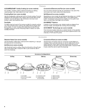
..., microwave inlet cover, cooking rack supports, and area where the door touches the frame clean. This occurs to avoid unintended starting of the microwave oven, under the bulb cover, and is located behind the vent grille at the beginning of abrasive cleanser or scrubbers. ■ Grease filter: mild soap and water or dishwasher. ■ Door and exterior: mild soap and water, or glass cleaner applied to paper towel. ■ Control panel: sponge...
..., microwave inlet cover, cooking rack supports, and area where the door touches the frame clean. This occurs to avoid unintended starting of the microwave oven, under the bulb cover, and is located behind the vent grille at the beginning of abrasive cleanser or scrubbers. ■ Grease filter: mild soap and water or dishwasher. ■ Door and exterior: mild soap and water, or glass cleaner applied to paper towel. ■ Control panel: sponge...
Owners Manual
Page 7
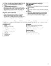
... tall grill rack, place the rack on the turntable and close the door. Replacement Parts, Accessories and Cleaning Supplies Following is being used. Program the microwave oven using these items during cooktop usage ■ This is not unusual. for some models) ■ Grease filter ■ Charcoal filter ■ Cooktop light bulb ■ Cavity light bulb ■ Steamer vessel (provided with some models) ■ Pan and handle (not provided) ■ Convection rack (provided with some models) ■ Grill rack (provided with some models) Cleaning...
... tall grill rack, place the rack on the turntable and close the door. Replacement Parts, Accessories and Cleaning Supplies Following is being used. Program the microwave oven using these items during cooktop usage ■ This is not unusual. for some models) ■ Grease filter ■ Charcoal filter ■ Cooktop light bulb ■ Cavity light bulb ■ Steamer vessel (provided with some models) ■ Pan and handle (not provided) ■ Convection rack (provided with some models) ■ Grill rack (provided with some models) Cleaning...
Owners Manual
Page 8
... user or operator instructions and/or installation instructions. 4. Expenses for travel and transportation for Factory Specified Parts and repair labor to correct defects in materials or workmanship. This warranty is not installed in accordance with original model/serial numbers that is located in a remote area where service by Whirlpool. 5. If you need assistance using your product, you can find your model number and serial number on the label located on how to use...
... user or operator instructions and/or installation instructions. 4. Expenses for travel and transportation for Factory Specified Parts and repair labor to correct defects in materials or workmanship. This warranty is not installed in accordance with original model/serial numbers that is located in a remote area where service by Whirlpool. 5. If you need assistance using your product, you can find your model number and serial number on the label located on how to use...

Warranty
Page 1
... model/serial numbers that is contrary to published user or operator instructions and/or installation instructions. 4. Consumable parts are excluded from the date of God, improper installation, installation not in which it is installed in an inaccessible location or is used in the country in accordance with any questions or concerns at the number below. Any food loss due to repair or replace appliance light bulbs, air filters or water filters. The removal...
... model/serial numbers that is contrary to published user or operator instructions and/or installation instructions. 4. Consumable parts are excluded from the date of God, improper installation, installation not in which it is installed in an inaccessible location or is used in the country in accordance with any questions or concerns at the number below. Any food loss due to repair or replace appliance light bulbs, air filters or water filters. The removal...


