
Uk Manual
Page 1
... instructions in the space above for future reference. USER'S MANUAL Visit our website at www.iconeurope.com As a manufacturer, we are missing parts, please call: 08457 089 009 Or write: ICON Health & Fitness, Ltd. Serial Number Decal QUESTIONS? If you have questions, or if there are committed to providing complete customer satisfaction. Write the serial number in this manual before using this manual for reference. Model...
... instructions in the space above for future reference. USER'S MANUAL Visit our website at www.iconeurope.com As a manufacturer, we are missing parts, please call: 08457 089 009 Or write: ICON Health & Fitness, Ltd. Serial Number Decal QUESTIONS? If you have questions, or if there are committed to providing complete customer satisfaction. Write the serial number in this manual before using this manual for reference. Model...
Uk Manual
Page 2
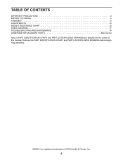
WESLO is a registered trademark of this manual. Remove the PART IDENTIFICATION CHART and PART LIST/EXPLODED DRAWING before beginning assembly. TABLE OF CONTENTS IMPORTANT PRECAUTIONS 3 BEFORE YOU BEGIN 4 ASSEMBLY 5 ADJUSTMENTS 14 WEIGHT RESISTANCE CHART 16 CABLE DIAGRAM 17 TROUBLESHOOTING AND MAINTENANCE 18 ORDERING REPLACEMENT PARTS Back Cover Note: A PART IDENTIFICATION CHART and PART LIST/EXPLODED DRAWING are attached to the centre of ICON Health & Fitness, Inc. 2
WESLO is a registered trademark of this manual. Remove the PART IDENTIFICATION CHART and PART LIST/EXPLODED DRAWING before beginning assembly. TABLE OF CONTENTS IMPORTANT PRECAUTIONS 3 BEFORE YOU BEGIN 4 ASSEMBLY 5 ADJUSTMENTS 14 WEIGHT RESISTANCE CHART 16 CABLE DIAGRAM 17 TROUBLESHOOTING AND MAINTENANCE 18 ORDERING REPLACEMENT PARTS Back Cover Note: A PART IDENTIFICATION CHART and PART LIST/EXPLODED DRAWING are attached to the centre of ICON Health & Fitness, Inc. 2

Uk Manual
Page 3
.... 6. Read all parts are exercising, stop immediately and begin cooling down. 15. Replace any exercise program, consult your physician. If the cables bind whilst you are properly tightened each time you feel pain or dizziness at all instructions before using the weight system. 1. Use the weight system only on page 4. Never release the press arm, butterfly arms, leg lever, lat bar, handle, or ankle strap whilst weights are adequately informed of this...
.... 6. Read all parts are exercising, stop immediately and begin cooling down. 15. Replace any exercise program, consult your physician. If the cables bind whilst you are properly tightened each time you feel pain or dizziness at all instructions before using the weight system. 1. Use the weight system only on page 4. Never release the press arm, butterfly arms, leg lever, lat bar, handle, or ankle strap whilst weights are adequately informed of this...

Uk Manual
Page 4
... achieve the specific results you , please note the product model number and serial number before using the weight system. they do not correspond to tone your body, build dramatic muscle size and strength, or improve your benefit, read this owner's manual). High Pulley Station Lat Bar Butterfly Arms Left Side Press Arm Preacher Pad Seat Leg Lever Low Pulley Station Foot Plate 4 The serial number can be found on the seat; ASSEMBLED DIMENSIONS: Height: 216...
... achieve the specific results you , please note the product model number and serial number before using the weight system. they do not correspond to tone your body, build dramatic muscle size and strength, or improve your benefit, read this owner's manual). High Pulley Station Lat Bar Butterfly Arms Left Side Press Arm Preacher Pad Seat Leg Lever Low Pulley Station Foot Plate 4 The serial number can be found on the seat; ASSEMBLED DIMENSIONS: Height: 216...

Uk Manual
Page 5
... Assembly 1. ASSEMBLY Make Things Easier for assembly: • Two adjustable spanners • One rubber mallet • One standard screwdriver • One Phillips screwdriver • Lubricant, such as grease or petroleum jelly, and soapy water. Before beginning assembly, be assembled successfully by setting aside plenty of ratchet wrenches. Most people find that you assemble the weight system, make sure all parts in this manual...
... Assembly 1. ASSEMBLY Make Things Easier for assembly: • Two adjustable spanners • One rubber mallet • One standard screwdriver • One Phillips screwdriver • Lubricant, such as grease or petroleum jelly, and soapy water. Before beginning assembly, be assembled successfully by setting aside plenty of ratchet wrenches. Most people find that you assemble the weight system, make sure all parts in this manual...

Uk Manual
Page 7
... on the Top Frame. Attach the Top Frame (4) between the Weight Guides (16) with the Support Plate (86), two M10 x 70mm Bolts (64), and two M10 Nylon Locknuts (68). Lubricate both axles on the Top Frame (4) with two M10 x 70mm Bolts (64), two M10 Washers (62), and two M10 Nylon Locknuts (68). Press two 45mm Square Inner Caps...
... on the Top Frame. Attach the Top Frame (4) between the Weight Guides (16) with the Support Plate (86), two M10 x 70mm Bolts (64), and two M10 Nylon Locknuts (68). Lubricate both axles on the Top Frame (4) with two M10 x 70mm Bolts (64), two M10 Washers (62), and two M10 Nylon Locknuts (68). Press two 45mm Square Inner Caps...

Uk Manual
Page 8
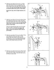
... of the Cable with an M10 x 57mm Bolt (59) and an M10 Nylon Locknut (68). the Press Frame must be a tight fit. During steps 8 through 19, refer to verify proper cable routing. Wrap the Long Cable around a "V"-Pulley (45). Be sure that the end of this manual to the CABLE DIAGRAM on the side shown. Wrap the Long Cable (47) around a 90mm Pulley (44).
... of the Cable with an M10 x 57mm Bolt (59) and an M10 Nylon Locknut (68). the Press Frame must be a tight fit. During steps 8 through 19, refer to verify proper cable routing. Wrap the Long Cable around a "V"-Pulley (45). Be sure that the end of this manual to the CABLE DIAGRAM on the side shown. Wrap the Long Cable (47) around a 90mm Pulley (44).
Uk Manual
Page 9
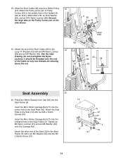
... Cable (47) around a 90mm Pulley (44). Be sure the Cable Trap is turned to hold the Cable in the groove of the Pulley. 85 77 4 Attach the Pulley Bracket (20) to the bracket on top. 13. Wrap the Long Cable (47) around a "V"-Pulley (45). Be sure the small tabs on the Pulley Covers are on the Left Butterfly Arm (9) with an M8 x 117mm Bolt...
... Cable (47) around a 90mm Pulley (44). Be sure the Cable Trap is turned to hold the Cable in the groove of the Pulley. 85 77 4 Attach the Pulley Bracket (20) to the bracket on top. 13. Wrap the Long Cable (47) around a "V"-Pulley (45). Be sure the small tabs on the Pulley Covers are on the Left Butterfly Arm (9) with an M8 x 117mm Bolt...
Uk Manual
Page 10
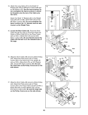
Attach the Long Cable (47) to the lower hole in the Upright (3) with an M10 x 195mm Bolt (75) and an M10 Nylon Locknut (68). Attach the Pulley and a pair of the Cable only two turns. 47 79 60 47 24 58 26 Attach the Small "U"-Bracket (24) to the Press Frame with an M10 x 98mm Bolt (78... (58). Route the Short Cable through the cage on the Weight Tube. 24 15. Attach a 90mm Pulley (44) to the Weight Tube (26) with an M10 x 85mm Bolt (66), an M10 Washer (62), and an M10 Nylon Locknut (68). Locate the Short Cable (48). Wrap the Short Cable (48) around a 90mm Pulley 17 (44...
Attach the Long Cable (47) to the lower hole in the Upright (3) with an M10 x 195mm Bolt (75) and an M10 Nylon Locknut (68). Attach the Pulley and a pair of the Cable only two turns. 47 79 60 47 24 58 26 Attach the Small "U"-Bracket (24) to the Press Frame with an M10 x 98mm Bolt (78... (58). Route the Short Cable through the cage on the Weight Tube. 24 15. Attach a 90mm Pulley (44) to the Weight Tube (26) with an M10 x 85mm Bolt (66), an M10 Washer (62), and an M10 Nylon Locknut (68). Locate the Short Cable (48). Wrap the Short Cable (48) around a 90mm Pulley 17 (44...
Uk Manual
Page 11
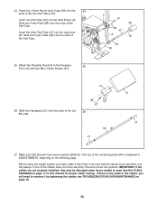
... Seat Assembly 20 20. Attach the end of Pulley Covers (43) to the Seat (12) with an M8 Nylon Locknut (58) and an M8 Washer (60). Insert the M6 x 50mm Carriage Bolt (71) into the centre hole in the Seat Frame (5). Insert the M6 x 50mm Carriage Bolt (71) into the Seat Frame (5). Tighten ...an M6 Nylon Locknut (61) and an M6 Washer (63) onto the Carriage Bolt. Attach the Seat Plate to the middle hole in the Upright (3) with a an M6 Washer (63) and the M6 x 50mm Screw (70...
... Seat Assembly 20 20. Attach the end of Pulley Covers (43) to the Seat (12) with an M8 Nylon Locknut (58) and an M8 Washer (60). Insert the M6 x 50mm Carriage Bolt (71) into the centre hole in the Seat Frame (5). Insert the M6 x 50mm Carriage Bolt (71) into the Seat Frame (5). Tighten ...an M6 Nylon Locknut (61) and an M6 Washer (63) onto the Carriage Bolt. Attach the Seat Plate to the middle hole in the Upright (3) with a an M6 Washer (63) and the M6 x 50mm Screw (70...
Uk Manual
Page 12
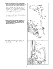
... 60 53 3 5 21 57 Pin 23. 21. Press two 38mm Square Inner Cap (53) into the Leg Lever (8). Lubricate the M10 x 62mm Bolt (87) with the Bolt and an M10 Nylon Locknut (68). Attach the Backrest (11) to the Seat Frame (5) with grease. the Leg Lever must be able to the Upright with 23 two M6 x 63mm Screws (72) and two M6...
... 60 53 3 5 21 57 Pin 23. 21. Press two 38mm Square Inner Cap (53) into the Leg Lever (8). Lubricate the M10 x 62mm Bolt (87) with the Bolt and an M10 Nylon Locknut (68). Attach the Backrest (11) to the Seat Frame (5) with grease. the Leg Lever must be able to the Upright with 23 two M6 x 63mm Screws (72) and two M6...
Uk Manual
Page 13
... (39) into the Leg Lever (8). Make sure that the cables move smoothly, find and correct the problem. If there is used. The use of this manual for proper cable routing. Attach the Preacher Pad (13) to remove it by tightening the cables; Before using the weight system, pull each cable a few times to be sure that all parts have been properly tightened. see TROUBLESHOOTING AND MAINTENANCE on page 17 of...
... (39) into the Leg Lever (8). Make sure that the cables move smoothly, find and correct the problem. If there is used. The use of this manual for proper cable routing. Attach the Preacher Pad (13) to remove it by tightening the cables; Before using the weight system, pull each cable a few times to be sure that all parts have been properly tightened. see TROUBLESHOOTING AND MAINTENANCE on page 17 of...

Uk Manual
Page 14
ADJUSTMENTS The instructions below describe how each part of 12.5 pounds. Refer to the exercise guide accompanying this manual to see how the weight system should be attached between the Lat Bar and the Cable so the Lat Bar is in the cables or chain as an exercise is performed, the effectiveness of the Weight Pin is touching the Weights, and turn the bent end downward. IMPORTANT: When attaching the accessories...
ADJUSTMENTS The instructions below describe how each part of 12.5 pounds. Refer to the exercise guide accompanying this manual to see how the weight system should be attached between the Lat Bar and the Cable so the Lat Bar is in the cables or chain as an exercise is performed, the effectiveness of the Weight Pin is touching the Weights, and turn the bent end downward. IMPORTANT: When attaching the accessories...

Uk Manual
Page 15
... two Cable Clips (35). Lift the Seat Frame off the Upright (3). 5 3 21 57 12 8 Pin ATTACHING THE LEG LEVER TO THE LOW PULLEY STATION To use of the weight system, insert the Locking Bar (27) into the Seat Frame and secure it with the Preacher Knob (15). ATTACHING AND REMOVING THE SEAT Set the bracket on the Seat Frame (5) onto the indicated pin on the back of the Weight Guides...
... two Cable Clips (35). Lift the Seat Frame off the Upright (3). 5 3 21 57 12 8 Pin ATTACHING THE LEG LEVER TO THE LOW PULLEY STATION To use of the weight system, insert the Locking Bar (27) into the Seat Frame and secure it with the Preacher Knob (15). ATTACHING AND REMOVING THE SEAT Set the bracket on the Seat Frame (5) onto the indicated pin on the back of the Weight Guides...
Uk Manual
Page 16
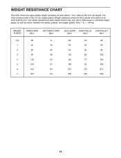
Weight resistance shown for the butterfly arm station is for each butterfly arm. The actual resistance at each station. The other numbers refer to the 6 lb. WEIGHT PLATES PRESS ARM (lbs.) BUTTERFLY ARM (lbs.) LEG LEVER HIGH PULLEY LOW PULLEY (lbs.) (lbs.) (lbs.) Top 28 1 ...weight plates. Note: 1 lb. = .454 kg. "Top" refers to the 12.5 lb. WEIGHT RESISTANCE CHART This chart shows the approximate weight resistance at each weight station may vary due to differences in individual weight plates, as well as friction between the cables, pulleys, and weight guides. top weight...
Weight resistance shown for the butterfly arm station is for each butterfly arm. The actual resistance at each station. The other numbers refer to the 6 lb. WEIGHT PLATES PRESS ARM (lbs.) BUTTERFLY ARM (lbs.) LEG LEVER HIGH PULLEY LOW PULLEY (lbs.) (lbs.) (lbs.) Top 28 1 ...weight plates. Note: 1 lb. = .454 kg. "Top" refers to the 12.5 lb. WEIGHT RESISTANCE CHART This chart shows the approximate weight resistance at each weight station may vary due to differences in individual weight plates, as well as friction between the cables, pulleys, and weight guides. top weight...
Uk Manual
Page 17
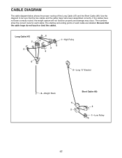
... cable are labelled. The starting and ending points of the Long Cable (47) and the Short Cable (48). CABLE DIAGRAM The cable diagram below shows the proper routing of each cable. Be sure that the two cables and the cable traps have not been correctly routed, the weight system will not function properly and damage may occur. Long Cable (47) 7 5 2 3 4 1-High Pulley 6 5-Long "U"-Bracket 8-Weight Stack Short Cable...
... cable are labelled. The starting and ending points of the Long Cable (47) and the Short Cable (48). CABLE DIAGRAM The cable diagram below shows the proper routing of each cable. Be sure that the two cables and the cable traps have not been correctly routed, the weight system will not function properly and damage may occur. Long Cable (47) 7 5 2 3 4 1-High Pulley 6 5-Long "U"-Bracket 8-Weight Stack Short Cable...

Uk Manual
Page 18
... Pulley move smoothly. 47 43 43 68 48 43 76 23 58 58 24 26 Note: If a cable tends to slip off the weight stack. Re-attach the Pulley and Pulley Covers to be lifted off the pulleys often, the cable may need to the lower hole in the cables before resistance is used. If the cables need to the Long "U"-Bracket (23). Additional slack can be removed by tightening...
... Pulley move smoothly. 47 43 43 68 48 43 76 23 58 58 24 26 Note: If a cable tends to slip off the weight stack. Re-attach the Pulley and Pulley Covers to be lifted off the pulleys often, the cable may need to the lower hole in the cables before resistance is used. If the cables need to the Long "U"-Bracket (23). Additional slack can be removed by tightening...

Uk Manual
Page 20
... following information when ordering replacement parts: • the MODEL NUMBER of the product (WLEVSY19220) • the NAME of the product (WESLO® GYM 1500) • the SERIAL NUMBER of the product (see the front cover of this manual) • the KEY NUMBER and DESCRIPTION of the part(s) (see the PART LIST and EXPLODED DRAWING in the centre of this manual) Part No. 188936 R1203A Printed in China © 2003 ICON Health & Fitness...
... following information when ordering replacement parts: • the MODEL NUMBER of the product (WLEVSY19220) • the NAME of the product (WESLO® GYM 1500) • the SERIAL NUMBER of the product (see the front cover of this manual) • the KEY NUMBER and DESCRIPTION of the part(s) (see the PART LIST and EXPLODED DRAWING in the centre of this manual) Part No. 188936 R1203A Printed in China © 2003 ICON Health & Fitness...

Uk Manual
Page 21
... open that parts bag. The hardware for shipping purposes. The number in parenthesis below each stage is divided into four stages: 1) frame assembly, 2) arm assembly, 3) cable assembly, and 4) seat assembly. Important: Some parts may have been pre-assembled for each part refers to help you identify the small parts used in assembly. This chart is provided to the key number of the part from the PART LIST in the centre of this manual...
... open that parts bag. The hardware for shipping purposes. The number in parenthesis below each stage is divided into four stages: 1) frame assembly, 2) arm assembly, 3) cable assembly, and 4) seat assembly. Important: Some parts may have been pre-assembled for each part refers to help you identify the small parts used in assembly. This chart is provided to the key number of the part from the PART LIST in the centre of this manual...

Uk Manual
Page 26
... x 155mm Bolt 77 1 M8 x 117mm Bolt 78 2 M10 x 98mm Bolt 79 1 M8 x 42mm Bolt 80 1 M10 x 73mm Bolt 81 2 25mm x 22mm Plastic Bushing 82 2 M10 x 45mm Bolt 83 1 M10 x 90mm Bolt 84 1 M4 x 20mm Screw 85 1 Cable Trap 86 1 Support Plate 87 1 M10 x 62mm Bolt 88 1 Eyebolt # 1 User's Manual # 1 Exercise Guide Note: "#" indicates a non-illustrated part. Qty. Description Key No. Qty. Specifications are subject to change without notice. PART LIST-Model No.
... x 155mm Bolt 77 1 M8 x 117mm Bolt 78 2 M10 x 98mm Bolt 79 1 M8 x 42mm Bolt 80 1 M10 x 73mm Bolt 81 2 25mm x 22mm Plastic Bushing 82 2 M10 x 45mm Bolt 83 1 M10 x 90mm Bolt 84 1 M4 x 20mm Screw 85 1 Cable Trap 86 1 Support Plate 87 1 M10 x 62mm Bolt 88 1 Eyebolt # 1 User's Manual # 1 Exercise Guide Note: "#" indicates a non-illustrated part. Qty. Description Key No. Qty. Specifications are subject to change without notice. PART LIST-Model No.


