
User Manual
Page 2
... proof of incidental or consequential damages. ICON OF/DU CANADA, 900 de l'Industrie, St-Jérôme, QC J7Y 4B8 WEIDER is limited in its scope and duration to the terms set forth above limitation may not apply to products used as store display...limited in its scope and duration to the original purchaser. TABLE OF CONTENTS LIMITED WARRANTY 2 IMPORTANT PRECAUTIONS 3 BEFORE YOU BEGIN 4 ASSEMBLY 5 CABLE DIAGRAMS 19 ADJUSTMENT 21 TROUBLE-SHOOTING AND MAINTENANCE 22 WEIGHT RESISTANCE CHART 23 ORDERING REPLACEMENT PARTS Back Cover Note: A PART LIST/EXPLODED DRAWING and...
... proof of incidental or consequential damages. ICON OF/DU CANADA, 900 de l'Industrie, St-Jérôme, QC J7Y 4B8 WEIDER is limited in its scope and duration to the terms set forth above limitation may not apply to products used as store display...limited in its scope and duration to the original purchaser. TABLE OF CONTENTS LIMITED WARRANTY 2 IMPORTANT PRECAUTIONS 3 BEFORE YOU BEGIN 4 ASSEMBLY 5 CABLE DIAGRAMS 19 ADJUSTMENT 21 TROUBLE-SHOOTING AND MAINTENANCE 22 WEIGHT RESISTANCE CHART 23 ORDERING REPLACEMENT PARTS Back Cover Note: A PART LIST/EXPLODED DRAWING and...
User Manual
Page 3
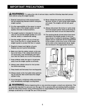
... strap while weights are exercising, stop immediately and begin cooling down. Always stand on the foot plate when performing an exercise that the cables are adequately informed of all instructions in this manual and in the locations shown. If you are raised. This is intended for foot ... especially important for personal injury or property damage sustained by or through the use the weight system in the appropriate location. 6. If the cables bind while you feel pain or dizziness while exercising, stop immediately and make sure that could cause the weight system to order a free ...
... strap while weights are exercising, stop immediately and begin cooling down. Always stand on the foot plate when performing an exercise that the cables are adequately informed of all instructions in this manual and in the locations shown. If you are raised. This is intended for foot ... especially important for personal injury or property damage sustained by or through the use the weight system in the appropriate location. 6. If the cables bind while you feel pain or dizziness while exercising, stop immediately and make sure that could cause the weight system to order a free ...
User Manual
Page 5
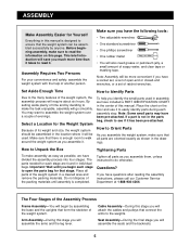
...needed for that there is completed. Important: Wait until assembly is enough room to walk around the weight system as shown in the drawings. Cable Assembly-During this stage you assemble them, unless instructed to ensure that all parts are found in individual bags. Before beginning assembly, make ... as you will assemble the seats and the backrests. 5 This brief introduction will save you much more convenient if you will attach the cables and pulleys that form the skeleton of soapy water, and clear tape or masking tape. To help of evenings. How to assemble the ...
...needed for that there is completed. Important: Wait until assembly is enough room to walk around the weight system as shown in the drawings. Cable Assembly-During this stage you assemble them, unless instructed to ensure that all parts are found in individual bags. Before beginning assembly, make ... as you will assemble the seats and the backrests. 5 This brief introduction will save you much more convenient if you will attach the cables and pulleys that form the skeleton of soapy water, and clear tape or masking tape. To help of evenings. How to assemble the ...
User Manual
Page 10
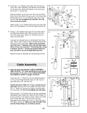
...17) and 3/8" Nylon Locknut (4). 52 90 81 32 33 83 79 49 17 4 79 13. For cable identification and routing during steps 14-32, refer to the Leg Lever (49) with the teeth down- 25...ward, on top of the Arm. 64 Lubricate Lubricate the indicated axle on pages 19 and 20. Secure the Cable to the Press Seat Frame with 3/8" Jam Nuts (18). 12. Attach the Leg Lever to the Bolts with...the direction shown. ing. Slide one end of the 3/8" x 1" Bolts (15). Attach the Pulley and a Cable Trap (39) to the inset draw- Wet the lower end of 13 the Right Butterfly Arm (68). Using ...
...17) and 3/8" Nylon Locknut (4). 52 90 81 32 33 83 79 49 17 4 79 13. For cable identification and routing during steps 14-32, refer to the Leg Lever (49) with the teeth down- 25...ward, on top of the Arm. 64 Lubricate Lubricate the indicated axle on pages 19 and 20. Secure the Cable to the Press Seat Frame with 3/8" Jam Nuts (18). 12. Attach the Leg Lever to the Bolts with...the direction shown. ing. Slide one end of the 3/8" x 1" Bolts (15). Attach the Pulley and a Cable Trap (39) to the inset draw- Wet the lower end of 13 the Right Butterfly Arm (68). Using ...

User Manual
Page 11
.... Note: It may be helpful to the other . Tighten the 3/8" x 1 3/4" Bolt (22). 11 72 5 22 36 Wrap the Medium Cable over a "V" Pulley (21) as shown. Wrap the Short Cable (71) over a 3 1/2" Pulley (5) as 15 shown. Make sure that are already mounted in the same manner. 16. Route the threaded shaft... on the Medium Cable (72) 18 under one side of the welded bracket on the Press Top Frame (63). 6 21 14 4 21 6 Welded Bracket 14 71 63 24...
.... Note: It may be helpful to the other . Tighten the 3/8" x 1 3/4" Bolt (22). 11 72 5 22 36 Wrap the Medium Cable over a "V" Pulley (21) as shown. Wrap the Short Cable (71) over a 3 1/2" Pulley (5) as 15 shown. Make sure that are already mounted in the same manner. 16. Route the threaded shaft... on the Medium Cable (72) 18 under one side of the welded bracket on the Press Top Frame (63). 6 21 14 4 21 6 Welded Bracket 14 71 63 24...

User Manual
Page 12
...the 19 64 Butterfly Top Frame (64) with a 3/8" x 1 3/4" Bolt (22) and a 3/8" Nylon Locknut (4). 22 4 34 72 20. Route the Long Cable (73) under a 3 1/2" Pulley (5) as shown. 4 Cable Guide 73 61 5 35 39 12 Route the end with a 5/16" x 1 3/4" Bolt (9) and a 5/16" Nylon 2 43 11 16 9 77 72 ...Locknut (2). 11 16 43 21. Identify the Long Cable (73). Note: See the 72 inset drawing. Attach the Pulley to the Weight Tube (77) with the loop through the slot in the direction shown...
...the 19 64 Butterfly Top Frame (64) with a 3/8" x 1 3/4" Bolt (22) and a 3/8" Nylon Locknut (4). 22 4 34 72 20. Route the Long Cable (73) under a 3 1/2" Pulley (5) as shown. 4 Cable Guide 73 61 5 35 39 12 Route the end with a 5/16" x 1 3/4" Bolt (9) and a 5/16" Nylon 2 43 11 16 9 77 72 ...Locknut (2). 11 16 43 21. Identify the Long Cable (73). Note: See the 72 inset drawing. Attach the Pulley to the Weight Tube (77) with the loop through the slot in the direction shown...

User Manual
Page 13
... 3/8" Nylon Locknut (4). 73 35 5 24. Wrap the Long Cable (73) over a 3 1/2" Pulley (5) in the direction shown. Attach the Pulley and a Cable 23 Trap (39) to the lower hole in the direction shown. Wrap the Long Cable (73) around a 3 1/2" Pulley (5) 22 in the direction...a 3/8" Flat Washer (17), and a 3/8" Nylon Locknut (4). Attach the Pulley and a Cable Trap (39) to the indicat- 24 ed bracket on the Butterfly Base (61) with a 3/8" x 2" Bolt (35) and a 3/8" Nylon Locknut (4). Attach the Pulley and a Cable Trap (39) to the Butterfly Upright (62) with a 3/8" x 2" Bolt (35)...
... 3/8" Nylon Locknut (4). 73 35 5 24. Wrap the Long Cable (73) over a 3 1/2" Pulley (5) in the direction shown. Attach the Pulley and a Cable 23 Trap (39) to the lower hole in the direction shown. Wrap the Long Cable (73) around a 3 1/2" Pulley (5) 22 in the direction...a 3/8" Flat Washer (17), and a 3/8" Nylon Locknut (4). Attach the Pulley and a Cable Trap (39) to the indicat- 24 ed bracket on the Butterfly Base (61) with a 3/8" x 2" Bolt (35) and a 3/8" Nylon Locknut (4). Attach the Pulley and a Cable Trap (39) to the Butterfly Upright (62) with a 3/8" x 2" Bolt (35)...

User Manual
Page 14
... (39) to the indicated hole in the Press Frame (53) with a 3/8" x 2" Bolt (35) and a 3/8" Nylon Locknut (4). In step 31, anoth- Attach the Pulley and a Cable 28 Trap (39) to the Press Frame Upright (59) with a 3/8" x 1 3/4" Bolt (22) and a 3/8" Nylon Locknut (4). Note: For clarity, this and the following drawings 25 show... the Pulley in the direction shown. er Pulley will be attached to the indicated bracket on the inside of the Press Frame and that the Cable Trap is oriented as shown. 14 36 4 22 5 73 73 5 35 39 4 60 59 73 5 23 39 4 73 53 39 17 28 45 Make ...
... (39) to the indicated hole in the Press Frame (53) with a 3/8" x 2" Bolt (35) and a 3/8" Nylon Locknut (4). In step 31, anoth- Attach the Pulley and a Cable 28 Trap (39) to the Press Frame Upright (59) with a 3/8" x 1 3/4" Bolt (22) and a 3/8" Nylon Locknut (4). Note: For clarity, this and the following drawings 25 show... the Pulley in the direction shown. er Pulley will be attached to the indicated bracket on the inside of the Press Frame and that the Cable Trap is oriented as shown. 14 36 4 22 5 73 73 5 35 39 4 60 59 73 5 23 39 4 73 53 39 17 28 45 Make ...

User Manual
Page 15
... (14) to create slack in the Press Frame (53) with a 3/8" x 3 1/4" Bolt (28), a 3/8" Flat Washer (17), and a 3/8" Nylon Locknut (4). Wrap the Long Cable (73) around a "V" Pulley (21) in the direction shown. Note: The small tube has three adjustment holes. Note: Lift the Top Weight (78) on the weight ... the small tube on the inside of the 3/8" x 2 1/2" Eyebolt (83). 83 49 73 15 Attach the Pulley and a Cable Trap (39) to the Leg Lever (49) by slipping the looped end of the Cable onto the looped end of the Press Frame and that the Pulley is mounted on the Press Seat...
... (14) to create slack in the Press Frame (53) with a 3/8" x 3 1/4" Bolt (28), a 3/8" Flat Washer (17), and a 3/8" Nylon Locknut (4). Wrap the Long Cable (73) around a "V" Pulley (21) in the direction shown. Note: The small tube has three adjustment holes. Note: Lift the Top Weight (78) on the weight ... the small tube on the inside of the 3/8" x 2 1/2" Eyebolt (83). 83 49 73 15 Attach the Pulley and a Cable Trap (39) to the Leg Lever (49) by slipping the looped end of the Cable onto the looped end of the Press Frame and that the Pulley is mounted on the Press Seat...
User Manual
Page 18
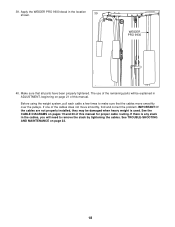
... IMPORTANT: If the cables are not properly installed, they may be explained in ADJUSTMENT, beginning on page 21 of the cables does not move smoothly over the pulleys. Apply the WEIDER PRO 9930 decal in the cables, you will be damaged when heavy weight is used. WEIDER PRO 9930 40. If one of... this manual for proper cable routing. If there is any slack in ...
... IMPORTANT: If the cables are not properly installed, they may be explained in ADJUSTMENT, beginning on page 21 of the cables does not move smoothly over the pulleys. Apply the WEIDER PRO 9930 decal in the cables, you will be damaged when heavy weight is used. WEIDER PRO 9930 40. If one of... this manual for proper cable routing. If there is any slack in ...
User Manual
Page 19
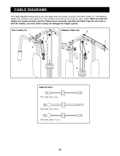
CABLE DIAGRAMS The cable diagrams below and on the next page show the correct route for each Cable. Incorrect cable routing can damage the weight system. Short Cable (71) 1 Medium Cable (72) 2 2 4 1 4 5 3 3 5 Cable ID Chart (71) 1.9m (6 ft. 3 in.) (72) 3.5m (11 ft. 6 in.) (73) 7.6m (24 ft. 11 in.) 19 Make sure that the Cables are routed correctly, that the Pulleys move smoothly, and that the Cable Traps do not touch or bind the Cables. The numbers show the proper routing of the Short Cable (71), the Medium Cable (72), and the Long Cable (73).
CABLE DIAGRAMS The cable diagrams below and on the next page show the correct route for each Cable. Incorrect cable routing can damage the weight system. Short Cable (71) 1 Medium Cable (72) 2 2 4 1 4 5 3 3 5 Cable ID Chart (71) 1.9m (6 ft. 3 in.) (72) 3.5m (11 ft. 6 in.) (73) 7.6m (24 ft. 11 in.) 19 Make sure that the Cables are routed correctly, that the Pulleys move smoothly, and that the Cable Traps do not touch or bind the Cables. The numbers show the proper routing of the Short Cable (71), the Medium Cable (72), and the Long Cable (73).
User Manual
Page 21
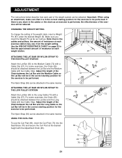
... system can be performed. Important: When using an attachment, make sure that it will be in the correct starting position for the exercise to the cables and pulleys, the amount of the weight stack, insert a Weight Pin (87) under the desired Weight (8). Make sure you insert the Weight Pin...21 For some exercises, the Chain (55) should be performed. The Nylon Strap (56) can be reduced. If there is any slack in the cables or the chain as it is performed, the effectiveness of the exercise will be in the correct starting position for the exercise to be attached...
... system can be performed. Important: When using an attachment, make sure that it will be in the correct starting position for the exercise to the cables and pulleys, the amount of the weight stack, insert a Weight Pin (87) under the desired Weight (8). Make sure you insert the Weight Pin...21 For some exercises, the Chain (55) should be performed. The Nylon Strap (56) can be reduced. If there is any slack in the cables or the chain as it is performed, the effectiveness of the exercise will be in the correct starting position for the exercise to be attached...
User Manual
Page 22
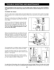
...Seat Frame (52). See the inset drawing. Tighten the 1/4" Nylon Locknut (16) at the second or third hole, as it . Remove the cable and re-install it will tight- Note: If additional adjustment is first used. Reattach the Pulley at the end of the Medium... different set of this , remove the 3/8" Nylon Locknut (4), 3/8" Flat Washer (17), and 3/8" x 2 1/2" Bolt (6). If the cables need to tighten the cables. If there is felt, the cables should be replaced, see ORDERING REPLACEMENT PARTS on weight systems can also be used on the back cover of holes in several different ways...
...Seat Frame (52). See the inset drawing. Tighten the 1/4" Nylon Locknut (16) at the second or third hole, as it . Remove the cable and re-install it will tight- Note: If additional adjustment is first used. Reattach the Pulley at the end of the Medium... different set of this , remove the 3/8" Nylon Locknut (4), 3/8" Flat Washer (17), and 3/8" x 2 1/2" Bolt (6). If the cables need to tighten the cables. If there is felt, the cables should be replaced, see ORDERING REPLACEMENT PARTS on weight systems can also be used on the back cover of holes in several different ways...
User Manual
Page 23
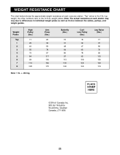
....5-lb. top weight; Note: The actual resistance at each station may vary due to differences in individual weight plates as well as friction between the cables, pulleys, and weight guides. weight plates. WEIGHT RESISTANCE CHART The chart below shows the approximate weight resistance at each exercise station. Weight Plates Top 1 2 3 4 5 6 7 8 High...
....5-lb. top weight; Note: The actual resistance at each station may vary due to differences in individual weight plates as well as friction between the cables, pulleys, and weight guides. weight plates. WEIGHT RESISTANCE CHART The chart below shows the approximate weight resistance at each exercise station. Weight Plates Top 1 2 3 4 5 6 7 8 High...
User Manual
Page 25
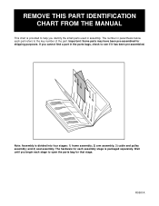
... the parts bag for that stage. The number in assembly. If you begin each assembly stage is divided into four stages: 1) frame assembly; 2) arm assembly; 3) cable and pulley assembly; The hardware for shipping purposes.
... the parts bag for that stage. The number in assembly. If you begin each assembly stage is divided into four stages: 1) frame assembly; 2) arm assembly; 3) cable and pulley assembly; The hardware for shipping purposes.
User Manual
Page 27
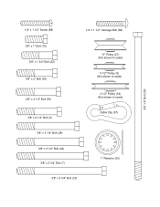
1/4" x 1 1/2" Screw (88) 1/4" x 1 1/2" Carriage Bolt (82) 3/8" x 8" Bolt (30) 3/8" x 1" Bolt (15) 3/8" x 1 3/4" Bolt (22) 3/8" x 2" Bolt (35) 3/8" x 2 1/4" Bolt (81) 3/8" x 2 1/2" Bolt (6) 3/8" x 3 1/4" Bolt (28) "V" Pulley (21) (Not shown to scale) 3 1/2" Pulley (5) (Not shown to scale) 4 1/2" Pulley (34) (Not shown to scale) Cable Clip (57) 3/8" x 3 1/2" Bolt (24) 3/8" x 3 3/4" Bolt (7) 3/8" x 4 3/4" Bolt (23) 1" Retainer (25)
1/4" x 1 1/2" Screw (88) 1/4" x 1 1/2" Carriage Bolt (82) 3/8" x 8" Bolt (30) 3/8" x 1" Bolt (15) 3/8" x 1 3/4" Bolt (22) 3/8" x 2" Bolt (35) 3/8" x 2 1/4" Bolt (81) 3/8" x 2 1/2" Bolt (6) 3/8" x 3 1/4" Bolt (28) "V" Pulley (21) (Not shown to scale) 3 1/2" Pulley (5) (Not shown to scale) 4 1/2" Pulley (34) (Not shown to scale) Cable Clip (57) 3/8" x 3 1/2" Bolt (24) 3/8" x 3 3/4" Bolt (7) 3/8" x 4 3/4" Bolt (23) 1" Retainer (25)
User Manual
Page 30
... 2 1/2" Bolt 3/8" Nylon Locknut 3 1/2" Pulley 3/8" x 2 1/2" Bolt 3/8" x 3 3/4" Bolt Weight 5/16" x 1 3/4" Bolt 1/4" x 2 1/2" Screw 1/4" Flat Washer 1/4" x 2 1/2" Carriage Bolt 1/4" x 3/4" Screw Long Cable Trap 3/8" x 1" Bolt 1/4" Nylon Locknut 3/8" Flat Washer 3/8" Jam Nut 5/16" Flat Washer 5/16" x 2 3/4" Bolt "V" Pulley 3/8" x 1 3/4" Bolt 3/8" x 4 3/4" Bolt 3/8" x 3 1/2" Bolt 1" Retainer 1" Round...Frame 10" Pad Backrest Left Butterfly Arm Right Butterfly Arm Curl Pad Curl Post Short Cable Medium Cable Long Cable Seat Bar Seat Brace Weight Tube Bumper Weight Tube Top Weight 1 1/2" Square Inner ...
... 2 1/2" Bolt 3/8" Nylon Locknut 3 1/2" Pulley 3/8" x 2 1/2" Bolt 3/8" x 3 3/4" Bolt Weight 5/16" x 1 3/4" Bolt 1/4" x 2 1/2" Screw 1/4" Flat Washer 1/4" x 2 1/2" Carriage Bolt 1/4" x 3/4" Screw Long Cable Trap 3/8" x 1" Bolt 1/4" Nylon Locknut 3/8" Flat Washer 3/8" Jam Nut 5/16" Flat Washer 5/16" x 2 3/4" Bolt "V" Pulley 3/8" x 1 3/4" Bolt 3/8" x 4 3/4" Bolt 3/8" x 3 1/2" Bolt 1" Retainer 1" Round...Frame 10" Pad Backrest Left Butterfly Arm Right Butterfly Arm Curl Pad Curl Post Short Cable Medium Cable Long Cable Seat Bar Seat Brace Weight Tube Bumper Weight Tube Top Weight 1 1/2" Square Inner ...


