
User Manual
Page 1
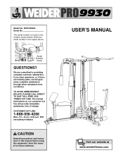
... missing parts, we will provide immediate assistance, free of charge. The trained technicians on our customer hot line will guarantee complete satisfaction through direct assistance from our factory. EST (excluding holidays) CAUTION Read all precautions and instructions in this manual before using this manual for future reference. The serial number is found in the space above. Write the serial number in the location shown...
... missing parts, we will provide immediate assistance, free of charge. The trained technicians on our customer hot line will guarantee complete satisfaction through direct assistance from our factory. EST (excluding holidays) CAUTION Read all precautions and instructions in this manual before using this manual for future reference. The serial number is found in the space above. Write the serial number in the location shown...
User Manual
Page 2
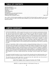
... the date of purchase. TABLE OF CONTENTS LIMITED WARRANTY 2 IMPORTANT PRECAUTIONS 3 BEFORE YOU BEGIN 4 ASSEMBLY 5 CABLE DIAGRAMS 19 ADJUSTMENT 21 TROUBLE-SHOOTING AND MAINTENANCE 22 WEIGHT RESISTANCE CHART 23 ORDERING REPLACEMENT PARTS Back Cover Note: A PART LIST/EXPLODED DRAWING and a PART IDENTIFICATION CHART are attached in the center of this warranty is limited to be free from defects in workmanship and material, under normal use and service conditions, for a period of one of its...
... the date of purchase. TABLE OF CONTENTS LIMITED WARRANTY 2 IMPORTANT PRECAUTIONS 3 BEFORE YOU BEGIN 4 ASSEMBLY 5 CABLE DIAGRAMS 19 ADJUSTMENT 21 TROUBLE-SHOOTING AND MAINTENANCE 22 WEIGHT RESISTANCE CHART 23 ORDERING REPLACEMENT PARTS Back Cover Note: A PART LIST/EXPLODED DRAWING and a PART IDENTIFICATION CHART are attached in the center of this warranty is limited to be free from defects in workmanship and material, under normal use and service conditions, for a period of one of its...
User Manual
Page 3
... the cables remain on the pulleys at all instructions before using. Read all users of the weight system are exercising, stop immediately and begin cooling down. It is missing or illegible, please call our Customer Service Department at the number on all of 12 and pets away from the weight system at all parts. Never release the press arm, butterfly arms, leg lever, lat bar, or nylon strap while weights...
... the cables remain on the pulleys at all instructions before using. Read all users of the weight system are exercising, stop immediately and begin cooling down. It is missing or illegible, please call our Customer Service Department at the number on all of 12 and pets away from the weight system at all parts. Never release the press arm, butterfly arms, leg lever, lat bar, or nylon strap while weights...
User Manual
Page 4
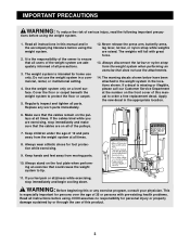
... Service Department toll-free at 1-888-936-4266, Mon.-Fri., 8 a.m.-6:30 p.m. The model number is to achieve the results you , please note the product model number and serial number before calling. EST (excluding holidays). ASSEMBLED DIMENSIONS: Height: 198 cm Width: 165 cm Depth: 86 cm Lat Bar High Pulley Station Butterfly Arms Backrest Curl Pad Adjustment Knob Low Pulley Station Foot Plate Weight Stack Backrest Press Arm Seat Leg Press Lever 4 The WEIDER® PRO 9930...
... Service Department toll-free at 1-888-936-4266, Mon.-Fri., 8 a.m.-6:30 p.m. The model number is to achieve the results you , please note the product model number and serial number before calling. EST (excluding holidays). ASSEMBLED DIMENSIONS: Height: 198 cm Width: 165 cm Depth: 86 cm Lat Bar High Pulley Station Butterfly Arms Backrest Curl Pad Adjustment Knob Low Pulley Station Foot Plate Weight Stack Backrest Press Arm Seat Leg Press Lever 4 The WEIDER® PRO 9930...
User Manual
Page 5
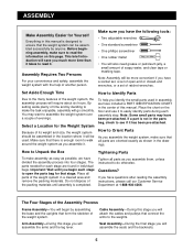
... has been pre-attached. Select a Location for the Weight System Because of its weight and size, the weight system should be used in assembly, we have a socket set, a set of ratchet wrenches. If a part is not in the location where it . The parts needed for each stage are oriented exactly as you assemble them, unless instructed to read the information on the floor and use it to easily...
... has been pre-attached. Select a Location for the Weight System Because of its weight and size, the weight system should be used in assembly, we have a socket set, a set of ratchet wrenches. If a part is not in the location where it . The parts needed for each stage are oriented exactly as you assemble them, unless instructed to read the information on the floor and use it to easily...

User Manual
Page 6
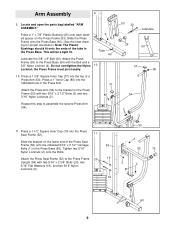
... understood the information on the lower end of the Butterfly Upright over the head of each Bolt. Do not tighten the Nylon Locknuts yet. 38 2 19 20 61 60 38 2 1 1 1 1 Position with two 5/16" x 2 3/4" Bolts (20), two 5/16" Flat Washers (19), and two 5/16" Nylon Locknuts (2). 2. Locate and open the parts bag labelled "FRAME ASSEMBLY." Note: If the Bolts fall out...
... understood the information on the lower end of the Butterfly Upright over the head of each Bolt. Do not tighten the Nylon Locknuts yet. 38 2 19 20 61 60 38 2 1 1 1 1 Position with two 5/16" x 2 3/4" Bolts (20), two 5/16" Flat Washers (19), and two 5/16" Nylon Locknuts (2). 2. Locate and open the parts bag labelled "FRAME ASSEMBLY." Note: If the Bolts fall out...
User Manual
Page 8
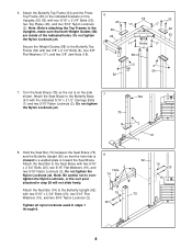
..." Nylon Locknuts (2). Secure the Weight Guides (58) to the Butterfly Base (61) with two 3/8" x 2 1/2" Bolts (6), four 3/8" 17 Holes 17 6 Flat Washers (17), and two 3/8" Jam Nuts (18). 58 2 2 59 62 7. Tighten all nylon locknuts used in step 38 will not slide freely. Hold the Seat Bar (74) between the Seat Brace (75) and the Butterfly Upright (62) so that the...
..." Nylon Locknuts (2). Secure the Weight Guides (58) to the Butterfly Base (61) with two 3/8" x 2 1/2" Bolts (6), four 3/8" 17 Holes 17 6 Flat Washers (17), and two 3/8" Jam Nuts (18). 58 2 2 59 62 7. Tighten all nylon locknuts used in step 38 will not slide freely. Hold the Seat Bar (74) between the Seat Brace (75) and the Butterfly Upright (62) so that the...
User Manual
Page 9
...: The Plastic Bushings should fit onto the ends of the tube in the Press Arm. Press a 1 3/4" Square Inner Cap (37) into the Press Seat Frame (52). 11 Slide the bracket on the lower end of a Press Arm (54). Press a 1" Inner Cap (80) into the indicated hole in the Press Base. Tighten two 5/16" Nylon Locknuts (2) onto the Bolts. Attach the Press Frame (53) to the...
...: The Plastic Bushings should fit onto the ends of the tube in the Press Arm. Press a 1 3/4" Square Inner Cap (37) into the Press Seat Frame (52). 11 Slide the bracket on the lower end of a Press Arm (54). Press a 1" Inner Cap (80) into the indicated hole in the Press Base. Tighten two 5/16" Nylon Locknuts (2) onto the Bolts. Attach the Press Frame (53) to the...
User Manual
Page 10
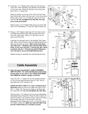
...Cable (71). Secure the Cable to the Press Seat Frame with a #10 x 1" Screw (32). Attach the Pulley and a Cable Trap (39) to the Leg Lever (49) with a 3/8" x 2" Bolt (35) and a 3/8" Nylon Locknut (4). Slide the bracket on each end of the Arm. 64 Lubricate Lubricate the indicated axle on pages 19 and 20. Wet the lower...and Right Butterfly Arms (67, 68). The Leg Lever must pivot easily. Refer to the CABLE DIAGRAMS and CABLE ID CHART on the Butterfly Top Frame (64). Open the parts bag labelled "CABLE ASSEMBLY AND PULLEYS." Slide one end of the Cable onto each Bolt with 3/8" ...
...Cable (71). Secure the Cable to the Press Seat Frame with a #10 x 1" Screw (32). Attach the Pulley and a Cable Trap (39) to the Leg Lever (49) with a 3/8" x 2" Bolt (35) and a 3/8" Nylon Locknut (4). Slide the bracket on each end of the Arm. 64 Lubricate Lubricate the indicated axle on pages 19 and 20. Wet the lower...and Right Butterfly Arms (67, 68). The Leg Lever must pivot easily. Refer to the CABLE DIAGRAMS and CABLE ID CHART on the Butterfly Top Frame (64). Open the parts bag labelled "CABLE ASSEMBLY AND PULLEYS." Slide one end of the Cable onto each Bolt with 3/8" ...

User Manual
Page 11
... 24 5 18 17 72 Pin 17. Attach the "V" Pulley and a Long Cable Trap (14) to one end and a threaded shaft on the Butterfly Upright (62) with a 3/8" x 2 1/2" Bolt (6) and a 3/8" Nylon Locknut (4). Note: It may be helpful to the other . Attach the Pulley and a Cable Trap (39) to the Press Top Frame (63) with a 3/8" x 3 3/4" Bolt (7). 2 5 39 7 72 63 18. Tighten the 3/8" x 1 3/4" Bolt (22). 11 72...
... 24 5 18 17 72 Pin 17. Attach the "V" Pulley and a Long Cable Trap (14) to one end and a threaded shaft on the Butterfly Upright (62) with a 3/8" x 2 1/2" Bolt (6) and a 3/8" Nylon Locknut (4). Note: It may be helpful to the other . Attach the Pulley and a Cable Trap (39) to the Press Top Frame (63) with a 3/8" x 3 3/4" Bolt (7). 2 5 39 7 72 63 18. Tighten the 3/8" x 1 3/4" Bolt (22). 11 72...

User Manual
Page 14
... sure that the Pulley is mounted on the Press Base (60) with a 3/8" x 3 1/4" Bolt (28), a 3/8" Flat Washer (17), and a 3/8" Nylon Locknut (4). Attach the Pulley and a Cable Trap (39) to the Bolt. 28. Hand tighten a 3/8" Nylon Locknut (4) two turns onto the Bolt. In step 31, anoth- Attach the Pulley and a Cable 28 Trap (39) to the indicated hole in the direction shown. er Pulley will be attached to the...
... sure that the Pulley is mounted on the Press Base (60) with a 3/8" x 3 1/4" Bolt (28), a 3/8" Flat Washer (17), and a 3/8" Nylon Locknut (4). Attach the Pulley and a Cable Trap (39) to the Bolt. 28. Hand tighten a 3/8" Nylon Locknut (4) two turns onto the Bolt. In step 31, anoth- Attach the Pulley and a Cable 28 Trap (39) to the indicated hole in the direction shown. er Pulley will be attached to the...

User Manual
Page 15
... 53 73 73 4 5 39 31. Attach the Pulley and a Cable Trap (39) to the small tube on the Press Seat Frame (52) with the Nylon Locknut. Route the Long Cable (73) around a 3 1/2" Pulley (5) and back through the opening in the Long Cable (73) before beginning this step. Attach the Long Cable (73) to the Bolt and secure them with a 3/8" x 3 1/4" Bolt (28), a 3/8" Flat Washer (17), and...
... 53 73 73 4 5 39 31. Attach the Pulley and a Cable Trap (39) to the small tube on the Press Seat Frame (52) with the Nylon Locknut. Route the Long Cable (73) around a 3 1/2" Pulley (5) and back through the opening in the Long Cable (73) before beginning this step. Attach the Long Cable (73) to the Bolt and secure them with a 3/8" x 3 1/4" Bolt (28), a 3/8" Flat Washer (17), and...

User Manual
Page 16
Locate and open the parts bag labelled "SEAT ASSEMBLY." Press four 3/4" Round Inner Caps (40) into the ends of the Seat (51) with a 1/4" Flat Washer (11) and a 1/4" Nylon Locknut (16). Insert the 1/4" x 2 1/2" Carriage Bolt (12) into the indicated holes in the Leg Lever (49) and the Press Seat Frame (52). Insert a 1/4" x 2" Carriage Bolt (85) into the center hole in the Press Seat Frame (52) and...
Locate and open the parts bag labelled "SEAT ASSEMBLY." Press four 3/4" Round Inner Caps (40) into the ends of the Seat (51) with a 1/4" Flat Washer (11) and a 1/4" Nylon Locknut (16). Insert the 1/4" x 2 1/2" Carriage Bolt (12) into the indicated holes in the Leg Lever (49) and the Press Seat Frame (52). Insert a 1/4" x 2" Carriage Bolt (85) into the center hole in the Press Seat Frame (52) and...
User Manual
Page 18
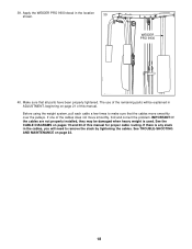
... problem. If one of this manual. See the CABLE DIAGRAMS on pages 19 and 20 of the cables does not move smoothly over the pulleys. IMPORTANT: If the cables are not properly installed, they may be explained in the location 39 shown. See TROUBLE-SHOOTING AND MAINTENANCE on page 21 of this manual for proper cable routing. If there is used. 39. The use of the remaining parts...
... problem. If one of this manual. See the CABLE DIAGRAMS on pages 19 and 20 of the cables does not move smoothly over the pulleys. IMPORTANT: If the cables are not properly installed, they may be explained in the location 39 shown. See TROUBLE-SHOOTING AND MAINTENANCE on page 21 of this manual for proper cable routing. If there is used. 39. The use of the remaining parts...
User Manual
Page 21
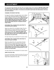
... insert the Weight Pin as far as an exercise is in the correct starting position for the exercise to the Long Cable (73) with the Adjustment Knob (45). 72 56 55 57 50 56 73 55 57 69 70 45 75 21 Adjust the length of resistance at each weight station. 8 87 ATTACHING THE LAT BAR OR NYLON STRAP TO THE HIGH PULLEY STATION Attach the Lat Bar (50...
... insert the Weight Pin as far as an exercise is in the correct starting position for the exercise to the Long Cable (73) with the Adjustment Knob (45). 72 56 55 57 50 56 73 55 57 69 70 45 75 21 Adjust the length of resistance at each weight station. 8 87 ATTACHING THE LAT BAR OR NYLON STRAP TO THE HIGH PULLEY STATION Attach the Lat Bar (50...
User Manual
Page 22
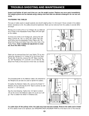
... far as needed , move one or both of the 3 1/2" Pulleys (5) to tighten the cables. To tighten the Medium Cable (72), remove the Small "U"Bracket (43) by relocating the indicated 3 1/2" Pulley (5) on the Medium Cable (72) attached to the Weights (8) can also be used to a different set of this , remove the 3/8" Nylon Locknut (4), 3/8" Flat Washer (17), and 3/8" x 2 1/2" Bolt (6). Remove the cable and re-install it will tight- The weight system can...
... far as needed , move one or both of the 3 1/2" Pulleys (5) to tighten the cables. To tighten the Medium Cable (72), remove the Small "U"Bracket (43) by relocating the indicated 3 1/2" Pulley (5) on the Medium Cable (72) attached to the Weights (8) can also be used to a different set of this , remove the 3/8" Nylon Locknut (4), 3/8" Flat Washer (17), and 3/8" x 2 1/2" Bolt (6). Remove the cable and re-install it will tight- The weight system can...
User Manual
Page 23
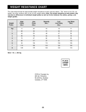
WEIGHT RESISTANCE CHART The chart below shows the approximate weight resistance at each exercise station. PLACE STAMP HERE ICON of Canada Inc. 900 de l'Industrie St-Jérôme, Québec Canada, J7Y 4B8 23 the other numbers refer to the 6-lb. Weight Plates Top 1 2 3 4 5 6 7 8 High Pulley (lbs.) 11 25 40 55 70 84 99 114 128 Arm Press (lbs.) 20 39 59...
WEIGHT RESISTANCE CHART The chart below shows the approximate weight resistance at each exercise station. PLACE STAMP HERE ICON of Canada Inc. 900 de l'Industrie St-Jérôme, Québec Canada, J7Y 4B8 23 the other numbers refer to the 6-lb. Weight Plates Top 1 2 3 4 5 6 7 8 High Pulley (lbs.) 11 25 40 55 70 84 99 114 128 Arm Press (lbs.) 20 39 59...
User Manual
Page 24
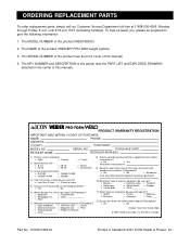
... about ICON products? EST (excluding holidays). o Bicycle o Exercise cycle o Treadmill o Home gym o Weight bench o Stepper o Cardio glide o Other____________ 11) Which types of the product (WEIDER® PRO 9930 weight system) 3. until 6:30 p.m. The NAME of magazines do you exercise? o Less than 3 times o 3 times or more 5) Have you consider purchasing fitness equipment from another ICON product? o Yes o No 6) Where did you first see the front cover of...
... about ICON products? EST (excluding holidays). o Bicycle o Exercise cycle o Treadmill o Home gym o Weight bench o Stepper o Cardio glide o Other____________ 11) Which types of the product (WEIDER® PRO 9930 weight system) 3. until 6:30 p.m. The NAME of magazines do you exercise? o Less than 3 times o 3 times or more 5) Have you consider purchasing fitness equipment from another ICON product? o Yes o No 6) Where did you first see the front cover of...
User Manual
Page 25
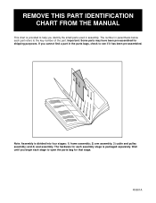
... each part refers to the key number of the part. The hardware for each assembly stage is divided into four stages: 1) frame assembly; 2) arm assembly; 3) cable and pulley assembly; R0501A Note: Assembly is packaged separately. Wait until you identify the small parts used in assembly. REMOVE THIS PART IDENTIFICATION CHART FROM THE MANUAL This chart is provided to help you begin each stage to open the parts bag for that stage. and 4) seat assembly.
... each part refers to the key number of the part. The hardware for each assembly stage is divided into four stages: 1) frame assembly; 2) arm assembly; 3) cable and pulley assembly; R0501A Note: Assembly is packaged separately. Wait until you identify the small parts used in assembly. REMOVE THIS PART IDENTIFICATION CHART FROM THE MANUAL This chart is provided to help you begin each stage to open the parts bag for that stage. and 4) seat assembly.
User Manual
Page 30
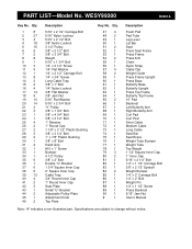
... Upright Press Top Frame Butterfly Top Frame 10" Pad Backrest Left Butterfly Arm Right Butterfly Arm Curl Pad Curl Post Short Cable Medium Cable Long Cable Seat Bar Seat Brace Weight Tube Bumper Weight Tube Top Weight 1 1/2" Square Inner Cap 1" Inner Cap 5/16" x 2 1/4" Bolt 1/4" x 1 1/2" Carriage Bolt 3/8" x 2 1/2" Eyebolt Weight Bumper 1/4" x 2" Carriage Bolt 1/4" x 2" Bolt Weight Pin 1/4" x 1 1/2" Screw Press Backrest 5/16" Jam Nut User's Manual Note: "#" indicates a non-illustrated part. Specifications are subject to change without notice. WESY99300 R0501A Key No. PART LIST-Model...
... Upright Press Top Frame Butterfly Top Frame 10" Pad Backrest Left Butterfly Arm Right Butterfly Arm Curl Pad Curl Post Short Cable Medium Cable Long Cable Seat Bar Seat Brace Weight Tube Bumper Weight Tube Top Weight 1 1/2" Square Inner Cap 1" Inner Cap 5/16" x 2 1/4" Bolt 1/4" x 1 1/2" Carriage Bolt 3/8" x 2 1/2" Eyebolt Weight Bumper 1/4" x 2" Carriage Bolt 1/4" x 2" Bolt Weight Pin 1/4" x 1 1/2" Screw Press Backrest 5/16" Jam Nut User's Manual Note: "#" indicates a non-illustrated part. Specifications are subject to change without notice. WESY99300 R0501A Key No. PART LIST-Model...


