

English Manual
Page 13
... Cables by comparing the lengths and the ends. Insert the Bolt through 58, refer to verify proper cable routing. Before beginning this manual to the CABLE DIAGRAMS on pages 30 and 31 of the Pulley. 85-72.5" 86-103" 87-148.75" 89-209.5" 88-243" 77 85 5 42 42... Nylon Locknut (42) onto the Bolt, but do not overtighten the bolts and nuts attaching the pulleys. The approximate length of the Butterfly Cable onto a 3/8" x 1" Bolt (77). Wrap the Butterfly Cable (85) around a 3 1/2" 25 Pulley (82) as shown and be able to pivot. 25. Locate and open the parts bags labeled ...
... Cables by comparing the lengths and the ends. Insert the Bolt through 58, refer to verify proper cable routing. Before beginning this manual to the CABLE DIAGRAMS on pages 30 and 31 of the Pulley. 85-72.5" 86-103" 87-148.75" 89-209.5" 88-243" 77 85 5 42 42... Nylon Locknut (42) onto the Bolt, but do not overtighten the bolts and nuts attaching the pulleys. The approximate length of the Butterfly Cable onto a 3/8" x 1" Bolt (77). Wrap the Butterfly Cable (85) around a 3 1/2" 25 Pulley (82) as shown and be able to pivot. 25. Locate and open the parts bags labeled ...

English Manual
Page 14
... 80 27. Note: The Left Arm (6) is positioned to hold the Cable in the groove of Pulley Plates (31) and 3 1/2" Pulleys (82). Wrap the Butterfly Cable (85) around a 3 1/2" Pulley (82) as shown and be positioned to hold the Cable in place. Locate one of the pre...-assembled pairs of the Pulley. 80 50 42 82 85 4 CABLE ASSEMBLY 28. Route the Butterfly Cable (85) under the indicated 3 1/2" Pulley (82). Leave just enough room for easier part identification. Tighten the 3/8" x 2" Bolt (50...
... 80 27. Note: The Left Arm (6) is positioned to hold the Cable in the groove of Pulley Plates (31) and 3 1/2" Pulleys (82). Wrap the Butterfly Cable (85) around a 3 1/2" Pulley (82) as shown and be positioned to hold the Cable in place. Locate one of the pre...-assembled pairs of the Pulley. 80 50 42 82 85 4 CABLE ASSEMBLY 28. Route the Butterfly Cable (85) under the indicated 3 1/2" Pulley (82). Leave just enough room for easier part identification. Tighten the 3/8" x 2" Bolt (50...

English Manual
Page 15
...50 82 86 15 Note: The 3 1/2" Pulley (82) in this is the shortest remaining Cable. Wrap the High Cable (86) around a 3 1/2" 30 Pulley (82). The Cable must be down 86 82 80 32. Route the High Cable around the 3 1/2" Pulley (82) attached to the inset drawing. Wrap ...the High Cable (86) around a 3 1/2" 32 Pulley (82). Route the High Cable (86) under the indicated 3 1/2" Pulley (82). The end of the...
...50 82 86 15 Note: The 3 1/2" Pulley (82) in this is the shortest remaining Cable. Wrap the High Cable (86) around a 3 1/2" 30 Pulley (82). The Cable must be down 86 82 80 32. Route the High Cable around the 3 1/2" Pulley (82) attached to the inset drawing. Wrap ...the High Cable (86) around a 3 1/2" 32 Pulley (82). Route the High Cable (86) under the indicated 3 1/2" Pulley (82). The end of the...

English Manual
Page 17
...positioned to the inset draw- Attach the Pulley and a Cable 37 Trap (80) to the Pulley Plates (31). The Cable must be routed from the direction shown. ing. Be sure that the Cable and Pulley move smoothly and that the Cable Trap is between the Pulley and the post. 66 80 82 ...87 1 38 43 17 Route the Press Cable (88) over the indicated 36 3 1/2" Pulley (82) attached to the Ab Upright (1) with a 3/8" x 3 1/2" Bolt (66), a 3/8" ...
...positioned to the inset draw- Attach the Pulley and a Cable 37 Trap (80) to the Pulley Plates (31). The Cable must be routed from the direction shown. ing. Be sure that the Cable and Pulley move smoothly and that the Cable Trap is between the Pulley and the post. 66 80 82 ...87 1 38 43 17 Route the Press Cable (88) over the indicated 36 3 1/2" Pulley (82) attached to the Ab Upright (1) with a 3/8" x 3 1/2" Bolt (66), a 3/8" ...

English Manual
Page 19
... the direction shown. 2 42 50 82 89 CABLE ASSEMBLY 43. Wrap the Low Cable (89) around a 3 1/2" Pulley (82). The Cable must be routed from the direction shown. 42 2 50 82 89 19 Attach a 3 1/2" Pulley (82) and a Cable Trap (80) to the Top 44 Frame (2) with a 3/8" x 2" Bolt (50) and a 3/8"...Large "U" Bracket. Wrap the Low Cable (89) around a 3 1/2" 42 Pulley (82). Note: This may come pre-assembled. 80 82 Route the Low Cable (89) through the Large "U" Bracket (84) and the 3 1/2" Pulley (82). Attach the Pulley to the upper hole 43 in the groove of 42 50 the...
... the direction shown. 2 42 50 82 89 CABLE ASSEMBLY 43. Wrap the Low Cable (89) around a 3 1/2" Pulley (82). The Cable must be routed from the direction shown. 42 2 50 82 89 19 Attach a 3 1/2" Pulley (82) and a Cable Trap (80) to the Top 44 Frame (2) with a 3/8" x 2" Bolt (50) and a 3/8"...Large "U" Bracket. Wrap the Low Cable (89) around a 3 1/2" 42 Pulley (82). Note: This may come pre-assembled. 80 82 Route the Low Cable (89) through the Large "U" Bracket (84) and the 3 1/2" Pulley (82). Attach the Pulley to the upper hole 43 in the groove of 42 50 the...

English Manual
Page 20
... the Cable in the groove of threads are showing above the Nylon Locknut, as shown in this step is 47 pre-assembled. Route the Press Cable (88) around the 3 1/2" Pulley (82) attached to the indi- 32 cated Weight Tube (25) with a 5/16" x 1 3/4" Bolt (68) and a 5/16" Nylon Locknut (40). 46. Be sure... 44 37 84 89 32 40 68 37 44 25 44 37 84 88 CABLE ASSEMBLY 88 80 42 82 50 13 20 Note: The 3 1/2" Pulley (82) in the inset drawing. It should be threaded onto the end of the Cable so only a couple of 46 the Press Cable (88) to...
... the Cable in the groove of threads are showing above the Nylon Locknut, as shown in this step is 47 pre-assembled. Route the Press Cable (88) around the 3 1/2" Pulley (82) attached to the indi- 32 cated Weight Tube (25) with a 5/16" x 1 3/4" Bolt (68) and a 5/16" Nylon Locknut (40). 46. Be sure... 44 37 84 89 32 40 68 37 44 25 44 37 84 88 CABLE ASSEMBLY 88 80 42 82 50 13 20 Note: The 3 1/2" Pulley (82) in the inset drawing. It should be threaded onto the end of the Cable so only a couple of 46 the Press Cable (88) to...

English Manual
Page 21
... It is pre-assembled. Route the Press Cable (88) over the indicated 3 1/2" Pulley (82) attached to the inset draw- Refer to the Pulley 49 Plates (31). Wrap the Press Cable (88) around a 3 1/2" Pulley (82). Wrap the Press Cable (88) around a 3 1/2" Pulley (82). ing. Attach the Pulley and a Cable 50 Trap ... hold the Cable in place. 88 82 66 80 88 66 38 12 4 38 43 42 80 82 21 Note: The 3 1/2" Pulley (82) in place. Route the Press Cable (88) around the 3 1/2" Pulley (82) attached to the Leg Press Upright (4) with a 3/8" x 3 1/2" Bolt (66), a 3/8" Washer (38) and a 3/8" Nylon...
... It is pre-assembled. Route the Press Cable (88) over the indicated 3 1/2" Pulley (82) attached to the inset draw- Refer to the Pulley 49 Plates (31). Wrap the Press Cable (88) around a 3 1/2" Pulley (82). Wrap the Press Cable (88) around a 3 1/2" Pulley (82). ing. Attach the Pulley and a Cable 50 Trap ... hold the Cable in place. 88 82 66 80 88 66 38 12 4 38 43 42 80 82 21 Note: The 3 1/2" Pulley (82) in place. Route the Press Cable (88) around the 3 1/2" Pulley (82) attached to the Leg Press Upright (4) with a 3/8" x 3 1/2" Bolt (66), a 3/8" Washer (38) and a 3/8" Nylon...

English Manual
Page 23
...- Attach the Large Backrest (19) to hold the Cable in place and that the Cable is routed as shown. Attach the "V" Pulley and a Large Cable Trap (83) to pivot. 59. Route the Press Cable (88) around a "V" 56 Pulley (81). Slide a 5/16" Washer (20) onto a 5/16" x 2 3/4" 58 Bolt (55). Slide ...Seat Frame (8). Leave enough room between the two Jam Nuts for easier part identification. Note: The 3 1/2" Pulley (82) used in this step was attached in place and that the Cable and Pulley move smoothly. 83 65 81 57. CABLE ASSEMBLY 56. Wrap the Press Cable (88) around the...
...- Attach the Large Backrest (19) to hold the Cable in place and that the Cable is routed as shown. Attach the "V" Pulley and a Large Cable Trap (83) to pivot. 59. Route the Press Cable (88) around a "V" 56 Pulley (81). Slide a 5/16" Washer (20) onto a 5/16" x 2 3/4" 58 Bolt (55). Slide ...Seat Frame (8). Leave enough room between the two Jam Nuts for easier part identification. Note: The 3 1/2" Pulley (82) used in this step was attached in place and that the Cable and Pulley move smoothly. 83 65 81 57. CABLE ASSEMBLY 56. Wrap the Press Cable (88) around the...

English Manual
Page 25
... the cables move smoothly, find and correct the problem. See TROUBLE-SHOOTING AND MAINTENANCE on page 30 and 31 of this manual for proper cable routing. Before using the home gym system, pull each cable a few times to the home gym system in the locations shown in HOW TO USE THE... decals from the decal sheets (not shown) and apply them to be explained in the illustration below. 64 HIGH PULLEY BUTTERFLY AB LEG EXTENSION/CURL ARM PRESS LEG PRESS SERIAL NUMBER DECAL LOW PULLEY/ROW 65. If there is used. 64. The use of the cables does not move smoothly over the...
... the cables move smoothly, find and correct the problem. See TROUBLE-SHOOTING AND MAINTENANCE on page 30 and 31 of this manual for proper cable routing. Before using the home gym system, pull each cable a few times to the home gym system in the locations shown in HOW TO USE THE... decals from the decal sheets (not shown) and apply them to be explained in the illustration below. 64 HIGH PULLEY BUTTERFLY AB LEG EXTENSION/CURL ARM PRESS LEG PRESS SERIAL NUMBER DECAL LOW PULLEY/ROW 65. If there is used. 64. The use of the cables does not move smoothly over the...
English Manual
Page 30
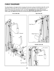
...CABLE DIAGRAMS The cable diagrams on this page and the next page show the proper route for each Cable have been assembled correctly. Press Cable (88) High Cable (86) 4 2 3 High Pulley-1 1-Long "U" Bracket 4 Weight Stack-5 5 76 11 8 2 3 9 12... 10 Leg Press-13 30 Butterfly Cable (85) 4 5-Left Arm 2 1-Right Arm 3 Use the diagrams to be sure that the Cables have been labeled. The numbers show the proper routing of each Cable. IMPORTANT: If the Cables have not been correctly routed, the WEIDER PRO 9735...
...CABLE DIAGRAMS The cable diagrams on this page and the next page show the proper route for each Cable have been assembled correctly. Press Cable (88) High Cable (86) 4 2 3 High Pulley-1 1-Long "U" Bracket 4 Weight Stack-5 5 76 11 8 2 3 9 12... 10 Leg Press-13 30 Butterfly Cable (85) 4 5-Left Arm 2 1-Right Arm 3 Use the diagrams to be sure that the Cables have been labeled. The numbers show the proper routing of each Cable. IMPORTANT: If the Cables have not been correctly routed, the WEIDER PRO 9735...


