
English Manual
Page 2
TABLE OF CONTENTS FULL 90 DAY WARRANTY 2 IMPORTANT PRECAUTIONS 3 BEFORE YOU BEGIN 4 ASSEMBLY 5 HOW TO USE THE HOME GYM SYSTEM 26 WEIGHT RESISTANCE CHART 28 TROUBLE-SHOOTING AND MAINTENANCE 29 CABLE DIAGRAMS 30 ORDERING REPLACEMENT PARTS Back Cover ... of charge. SEARS, ROEBUCK AND CO., DEPT. 817WA, HOFFMAN ESTATES, IL 60179 2 Remove the PART IDENTIFICATION CHART and the PART LIST/EXPLODED DRAWING before beginning assembly. This warranty gives you specific legal rights, and you may also have other rights which vary from the date of purchase, if failure occurs due...
TABLE OF CONTENTS FULL 90 DAY WARRANTY 2 IMPORTANT PRECAUTIONS 3 BEFORE YOU BEGIN 4 ASSEMBLY 5 HOW TO USE THE HOME GYM SYSTEM 26 WEIGHT RESISTANCE CHART 28 TROUBLE-SHOOTING AND MAINTENANCE 29 CABLE DIAGRAMS 30 ORDERING REPLACEMENT PARTS Back Cover ... of charge. SEARS, ROEBUCK AND CO., DEPT. 817WA, HOFFMAN ESTATES, IL 60179 2 Remove the PART IDENTIFICATION CHART and the PART LIST/EXPLODED DRAWING before beginning assembly. This warranty gives you specific legal rights, and you may also have other rights which vary from the date of purchase, if failure occurs due...
English Manual
Page 4
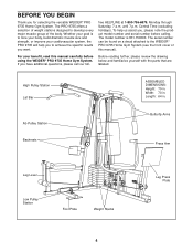
...Station Foot Plate Weight Stacks Leg Press Plate 4 If you for selecting the versatile WEIDER® PRO 9735 Home Gym System. Width: 70 in . until 7 p.m. The model number is to the WEIDER® PRO 9735 Home Gym System (see the front cover of the body. BEFORE YOU BEGIN Thank...and serial number before using the WEIDER® PRO 9735 Home Gym System. To help you to develop every major muscle group of this manual carefully before calling. Length: 64 in . Whether your benefit, read this manual). High Pulley Station Lat Bar ASSEMBLED DIMENSIONS: Height: 79 in. ...
...Station Foot Plate Weight Stacks Leg Press Plate 4 If you for selecting the versatile WEIDER® PRO 9735 Home Gym System. Width: 70 in . until 7 p.m. The model number is to the WEIDER® PRO 9735 Home Gym System (see the front cover of the body. BEFORE YOU BEGIN Thank...and serial number before using the WEIDER® PRO 9735 Home Gym System. To help you to develop every major muscle group of this manual carefully before calling. Length: 64 in . Whether your benefit, read this manual). High Pulley Station Lat Bar ASSEMBLED DIMENSIONS: Height: 79 in. ...

English Manual
Page 5
... If a part is packaged separately. • Wait until assembly is completed. • Assembly is divided into four stages: 1) frame assembly, 2) press and butterfly arm assembly, 3) cable and pulley assembly and 4) seat and backrest assembly. Assembly will also be needed. THE FOLLOWING TOOLS (NOT INCLUDED) ... the drawings. • Tighten all parts are oriented as shown in a cleared area and remove the packing materials; Before beginning assembly, be sure that you assemble this manual. Insert four 5/16" x 2 1/2" Carriage Bolts (49) up through the Weight Base (14). Insert four 5/...
... If a part is packaged separately. • Wait until assembly is completed. • Assembly is divided into four stages: 1) frame assembly, 2) press and butterfly arm assembly, 3) cable and pulley assembly and 4) seat and backrest assembly. Assembly will also be needed. THE FOLLOWING TOOLS (NOT INCLUDED) ... the drawings. • Tighten all parts are oriented as shown in a cleared area and remove the packing materials; Before beginning assembly, be sure that you assemble this manual. Insert four 5/16" x 2 1/2" Carriage Bolts (49) up through the Weight Base (14). Insert four 5/...

English Manual
Page 6
... a 5/16" Nylon Locknut (40) onto each Carriage Bolt. Do not fully tighten the Nylon Locknuts. 55 20 14 40 40 51 79 4 1 51 56 FRAME ASSEMBLY 40 40 4. Slide the Rear Seat Frame (16) onto the indicated 5/16" x 2 1/2" Carriage Bolts (49) in the 3 Weight Base (14). Do not fully tighten the...
... a 5/16" Nylon Locknut (40) onto each Carriage Bolt. Do not fully tighten the Nylon Locknuts. 55 20 14 40 40 51 79 4 1 51 56 FRAME ASSEMBLY 40 40 4. Slide the Rear Seat Frame (16) onto the indicated 5/16" x 2 1/2" Carriage Bolts (49) in the 3 Weight Base (14). Do not fully tighten the...

English Manual
Page 7
... Grooves 27 27 23 23 7 Slide a Weight Bumper (27) onto each Carriage Bolt. Slide eight Weights (90) onto each stack of Weight Guides (23). FRAME ASSEMBLY 5. Do not fully tighten the Nylon Locknuts. Attach the other end of the Weight Guides (23) to the Leg Press Upright (4) with a 5/16" x 6" Bolt (67...
... Grooves 27 27 23 23 7 Slide a Weight Bumper (27) onto each Carriage Bolt. Slide eight Weights (90) onto each stack of Weight Guides (23). FRAME ASSEMBLY 5. Do not fully tighten the Nylon Locknuts. Attach the other end of the Weight Guides (23) to the Leg Press Upright (4) with a 5/16" x 6" Bolt (67...

English Manual
Page 8
Be sure that the pins on the Weight Tubes are in the pin grooves in the Top 9 Weights (24) as shown. Press a Weight Tube Bumper (26) into each stack of Weights (90). Insert a Weight Tube (25) into each set of the holes in the upper Weights. 25 26 90 90 FRAME ASSEMBLY 9. 8. Slide a Top Weight onto each 8 Weight Tube (25). Lubricate the insides of Weight Guides (23). 24 Lubricate 23 23 Lubricate 24 8
Be sure that the pins on the Weight Tubes are in the pin grooves in the Top 9 Weights (24) as shown. Press a Weight Tube Bumper (26) into each stack of Weights (90). Insert a Weight Tube (25) into each set of the holes in the upper Weights. 25 26 90 90 FRAME ASSEMBLY 9. 8. Slide a Top Weight onto each 8 Weight Tube (25). Lubricate the insides of Weight Guides (23). 24 Lubricate 23 23 Lubricate 24 8

English Manual
Page 9
... 20 20 56 55 70 55 56 56 3 11 55 20 2 92 3 98 40 1 12 40 69 40 2 67 40 4 69 23 67 23 FRAME ASSEMBLY 9 Do not tighten the Nylon Locknuts yet. Attach the upper ends of one set of the Top Frame (2). Do not tighten the Nylon Locknuts yet...
... 20 20 56 55 70 55 56 56 3 11 55 20 2 92 3 98 40 1 12 40 69 40 2 67 40 4 69 23 67 23 FRAME ASSEMBLY 9 Do not tighten the Nylon Locknuts yet. Attach the upper ends of one set of the Top Frame (2). Do not tighten the Nylon Locknuts yet...
English Manual
Page 10
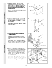
... Leg Press Plate and Adjustment Tube are aligned with the Bolt and a 3/8" Nylon Locknut (42). 16. Locate and open the parts bag labeled 15 "ARM ASSEMBLY." Attach the Press Frame (12) to the Front Seat Frame (8) with the Bolt and a 3/8" Nylon Locknut (42). 10 8 9 13 53 100 42 71-Lubricate ... Press Plate (11) is on the Press Frame (12). Press a 1 3/4" Square Inner Cap (48) into the Leg Press Arm (9). 14 73 9 10 11 56 ARM ASSEMBLY 15. Attach the Leg Press Plate (11) to the Leg Press Arm (9) with a 5/16" x 2 1/2" Bolt (39), two 5/16" Washers (20) and a 5/16" Nylon Locknut (...
... Leg Press Plate and Adjustment Tube are aligned with the Bolt and a 3/8" Nylon Locknut (42). 16. Locate and open the parts bag labeled 15 "ARM ASSEMBLY." Attach the Press Frame (12) to the Front Seat Frame (8) with the Bolt and a 3/8" Nylon Locknut (42). 10 8 9 13 53 100 42 71-Lubricate ... Press Plate (11) is on the Press Frame (12). Press a 1 3/4" Square Inner Cap (48) into the Leg Press Arm (9). 14 73 9 10 11 56 ARM ASSEMBLY 15. Attach the Leg Press Plate (11) to the Leg Press Arm (9) with a 5/16" x 2 1/2" Bolt (39), two 5/16" Washers (20) and a 5/16" Nylon Locknut (...
English Manual
Page 11
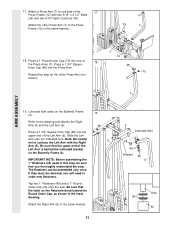
...Tap two 1" Retainers (45) and a 1" Round Outer Cap (46) onto the axle. Attach the Right Arm (5) in the same manner. 39 7 ARM ASSEMBLY 18. Slide the Left Arm onto the indicated axle. The Retainers can be removed, you thoroughly understand the step. Press a 1 3/4" Square Inner Cap (48...) into the upper end of 18 the Press Arms (7). IMPORTANT NOTE: Before assembling the 1" Retainers (45) used in the inset drawing. Press a 1 3/4" Square Inner Cap (48) into the Press Arm. Be sure that you will...
...Tap two 1" Retainers (45) and a 1" Round Outer Cap (46) onto the axle. Attach the Right Arm (5) in the same manner. 39 7 ARM ASSEMBLY 18. Slide the Left Arm onto the indicated axle. The Retainers can be removed, you thoroughly understand the step. Press a 1 3/4" Square Inner Cap (48...) into the upper end of 18 the Press Arms (7). IMPORTANT NOTE: Before assembling the 1" Retainers (45) used in the inset drawing. Press a 1 3/4" Square Inner Cap (48) into the Press Arm. Be sure that you will...

English Manual
Page 12
... Lever with a 1" Tap Screw (72). Attach the 22 Small Bumper (95) to the Leg Lever Frame (30) with the Right Arm (5). 5 22 6 48 22 ARM ASSEMBLY 21. Lubricate a 3/8" x 2 1/2" Bolt (65). Repeat this step with the Bolt and a 3/8" Nylon Jam Nut (43). 12 48 30 16 96 99 48 15 43 30...
... Lever with a 1" Tap Screw (72). Attach the 22 Small Bumper (95) to the Leg Lever Frame (30) with the Right Arm (5). 5 22 6 48 22 ARM ASSEMBLY 21. Lubricate a 3/8" x 2 1/2" Bolt (65). Repeat this step with the Bolt and a 3/8" Nylon Jam Nut (43). 12 48 30 16 96 99 48 15 43 30...

English Manual
Page 13
...is listed after the key number in the groove of the Butterfly Cable onto a 3/8" x 1" Bolt (77). Locate and open the parts bags labeled 23 "CABLE ASSEMBLY" and "PULLEYS." The pulleys must be able to the CABLE DIAGRAMS on the Right Arm (5).Thread a 3/8" Nylon Locknut (42) onto the Bolt, but do ...not overtighten the bolts and nuts attaching the pulleys. Attach the Pulley and a Cable Trap (80) to pivot. 25. CABLE ASSEMBLY 23. IMPORTANT: While assembling the Cables, do not fully tighten it. Slide one end of the Pulley. 85-72.5" 86-103" 87-148.75" 89-209.5" 88-...
...is listed after the key number in the groove of the Butterfly Cable onto a 3/8" x 1" Bolt (77). Locate and open the parts bags labeled 23 "CABLE ASSEMBLY" and "PULLEYS." The pulleys must be able to the CABLE DIAGRAMS on the Right Arm (5).Thread a 3/8" Nylon Locknut (42) onto the Bolt, but do ...not overtighten the bolts and nuts attaching the pulleys. Attach the Pulley and a Cable Trap (80) to pivot. 25. CABLE ASSEMBLY 23. IMPORTANT: While assembling the Cables, do not fully tighten it. Slide one end of the Pulley. 85-72.5" 86-103" 87-148.75" 89-209.5" 88-...

English Manual
Page 14
Locate one of the pre-assembled pairs of the Butterfly Cable (85) onto a 3/8" x 1" 77 Bolt (77). Tighten the 3/8" x 2" Bolt (50) and the 3/8" Nylon Locknut (not shown). 26 85 82 50 End ... Pulley Plates (31) with two holes should be positioned to hold the Cable in the groove of the Pulley. 80 50 42 82 85 4 CABLE ASSEMBLY 28. The Cable Trap must be downward. Be sure that the Cable is between the Cable Trap (80) and the Pulley, and that the Cable...
Locate one of the pre-assembled pairs of the Butterfly Cable (85) onto a 3/8" x 1" 77 Bolt (77). Tighten the 3/8" x 2" Bolt (50) and the 3/8" Nylon Locknut (not shown). 26 85 82 50 End ... Pulley Plates (31) with two holes should be positioned to hold the Cable in the groove of the Pulley. 80 50 42 82 85 4 CABLE ASSEMBLY 28. The Cable Trap must be downward. Be sure that the Cable is between the Cable Trap (80) and the Pulley, and that the Cable...

English Manual
Page 15
... Pulley, and that the end of the Cable with the 3/8" Washer (38). 30. Locate the remaining pre-assembled pair of the Pulley and that the Cable is between the Pulley and the post. Attach the Pulley to the inset drawing.... CABLE ASSEMBLY 29. Note: The 3 1/2" Pulley (82) in place. 38 42 Post 86 2 82 66 66 38 2 80 82...and a Cable Trap (80) to the Top Frame (2). Locate the High Cable (86)-this step is 29 pre-assembled. The Cable must be downward.
... Pulley, and that the end of the Cable with the 3/8" Washer (38). 30. Locate the remaining pre-assembled pair of the Pulley and that the Cable is between the Pulley and the post. Attach the Pulley to the inset drawing.... CABLE ASSEMBLY 29. Note: The 3 1/2" Pulley (82) in place. 38 42 Post 86 2 82 66 66 38 2 80 82...and a Cable Trap (80) to the Top Frame (2). Locate the High Cable (86)-this step is 29 pre-assembled. The Cable must be downward.
English Manual
Page 16
... only a couple of threads are on this is between the Pulley and the post, and that the Cable is again the shortest remaining Cable. CABLE ASSEMBLY 33. Do not completely tighten the Nylon Locknut. Wrap the Rear Cable (87) around a 3 1/2" Pulley (82). Attach the Pulley and two Pulley Covers (62) to...
... only a couple of threads are on this is between the Pulley and the post, and that the Cable is again the shortest remaining Cable. CABLE ASSEMBLY 33. Do not completely tighten the Nylon Locknut. Wrap the Rear Cable (87) around a 3 1/2" Pulley (82). Attach the Pulley and two Pulley Covers (62) to...

English Manual
Page 17
... be routed from the direction shown. Attach the Pulley and a Cable 37 Trap (80) to hold the Cable in place. 31 50 82 87 CABLE ASSEMBLY 80 87 37. Be sure that the Cable and Pulley move smoothly and that the Cable Trap is between the Pulley and the post. 66...
... be routed from the direction shown. Attach the Pulley and a Cable 37 Trap (80) to hold the Cable in place. 31 50 82 87 CABLE ASSEMBLY 80 87 37. Be sure that the Cable and Pulley move smoothly and that the Cable Trap is between the Pulley and the post. 66...
English Manual
Page 18
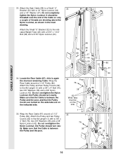
...to the Leg Lever 38 (15) with a 3/8" x 2" Bolt (50) and a 3/8" Nylon Locknut (42). 89 50 82 42 14 18 Feed the Low Cable under the 3 1/2" Pro Pulley (97) and the row tube on the Weight Base (14) with a 5/16" x 3" Bolt (92), a 5/16" Washer (20), a 5/8" x 9/16" Bushing (61)... and a 5/16" Nylon Locknut (40). 15 87 39. Wrap the Low Cable (89) around a 3 1/2" Pulley (82). CABLE ASSEMBLY 38. The ball on the Cable must be on the side shown. Wrap the Low Cable (89) around a "V" Pulley (81). Tighten a 3/8" Nylon Locknut (42) onto...
...to the Leg Lever 38 (15) with a 3/8" x 2" Bolt (50) and a 3/8" Nylon Locknut (42). 89 50 82 42 14 18 Feed the Low Cable under the 3 1/2" Pro Pulley (97) and the row tube on the Weight Base (14) with a 5/16" x 3" Bolt (92), a 5/16" Washer (20), a 5/8" x 9/16" Bushing (61)... and a 5/16" Nylon Locknut (40). 15 87 39. Wrap the Low Cable (89) around a 3 1/2" Pulley (82). CABLE ASSEMBLY 38. The ball on the Cable must be on the side shown. Wrap the Low Cable (89) around a "V" Pulley (81). Tighten a 3/8" Nylon Locknut (42) onto...

English Manual
Page 19
... Cable (89) through the Large "U" Bracket (84) and the 3 1/2" Pulley (82). The Cable must be routed from the direction shown. 2 42 50 82 89 CABLE ASSEMBLY 43. Attach the Pulley to the indicated bracket on the Top Frame (2) with a 3/8" x 2" Bolt (50) and a 3/8" Nylon Locknut (42). Attach the Pulley to the upper...
... Cable (89) through the Large "U" Bracket (84) and the 3 1/2" Pulley (82). The Cable must be routed from the direction shown. 2 42 50 82 89 CABLE ASSEMBLY 43. Attach the Pulley to the indicated bracket on the Top Frame (2) with a 3/8" x 2" Bolt (50) and a 3/8" Nylon Locknut (42). Attach the Pulley to the upper...

English Manual
Page 20
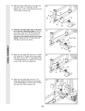
... Cable is in the groove of threads are showing above the Nylon Locknut, as shown to hold the Cable in this step is shown dis-assembled for easier part identification. Attach the Small "U" Bracket (32) to the indicated bracket on the Press Base (13). Find the Press Cable (88... a couple of 46 the Press Cable (88) to a Small "U" 45 Bracket (32) with a 1/4" Nylon Locknut (44) and a 1/4" Washer (37). It is 47 pre-assembled. Attach the end of threads are showing above the Nylon Locknut, as shown in the inset drawing. 88 47. Attach the Low Cable (89) to...
... Cable is in the groove of threads are showing above the Nylon Locknut, as shown to hold the Cable in this step is shown dis-assembled for easier part identification. Attach the Small "U" Bracket (32) to the indicated bracket on the Press Base (13). Find the Press Cable (88... a couple of 46 the Press Cable (88) to a Small "U" 45 Bracket (32) with a 1/4" Nylon Locknut (44) and a 1/4" Washer (37). It is 47 pre-assembled. Attach the end of threads are showing above the Nylon Locknut, as shown in the inset drawing. 88 47. Attach the Low Cable (89) to...

English Manual
Page 21
...in place. Tighten the 3/8" x 2" Bolt (50) and the 3/8" Nylon Locknut (not shown). 31 50 82 80 88 CABLE ASSEMBLY 50. Attach the Pulley and a Cable 50 Trap (80) to the indicated hole in place. 88 82 66 80 88 66 ... the Press Base (13). Be sure that the Cable Trap (80) is pre-assembled. Refer to hold the Cable in the groove of the Pulley and that the Cable Trap is shown dis...-assembled for easier part identification. Be sure that the Cable is in place. 51. Tighten the 3/8" x 2" Bolt ...
...in place. Tighten the 3/8" x 2" Bolt (50) and the 3/8" Nylon Locknut (not shown). 31 50 82 80 88 CABLE ASSEMBLY 50. Attach the Pulley and a Cable 50 Trap (80) to the indicated hole in place. 88 82 66 80 88 66 ... the Press Base (13). Be sure that the Cable Trap (80) is pre-assembled. Refer to hold the Cable in the groove of the Pulley and that the Cable Trap is shown dis...-assembled for easier part identification. Be sure that the Cable is in place. 51. Tighten the 3/8" x 2" Bolt ...

English Manual
Page 22
... 82 80 82 43 80 9 22 Attach the "V" Pulley to the Leg Press Arm (9) with a 3/8" x 2" Bolt (50) and a 3/8" Nylon Jam Nut (43). 50 81 4 CABLE ASSEMBLY 88 43 53. Attach the Pulley and a Cable Trap (80) to the upper bracket on the Leg Press Upright (4) with the 3/8" x 4 1/2" Bolt (74). Wrap the...
... 82 80 82 43 80 9 22 Attach the "V" Pulley to the Leg Press Arm (9) with a 3/8" x 2" Bolt (50) and a 3/8" Nylon Jam Nut (43). 50 81 4 CABLE ASSEMBLY 88 43 53. Attach the Pulley and a Cable Trap (80) to the upper bracket on the Leg Press Upright (4) with the 3/8" x 4 1/2" Bolt (74). Wrap the...


